Table of Contents
Advertisement
GL
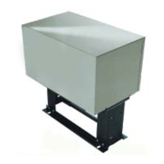
MODEL SL540
M
D
S
G
O
EDIUM
UTY
LIDE
ATE
PERATOR
MODEL SL570
H
D
, S
G
O
EAVY
UTY
LIDE
ATE
PERATOR
2 YEAR WARRANTY
Serial # ________________________
(located on electrical box cover)
Installation Date __________________
MODELS SL540 AND SL570 ARE FOR VEHICULAR PASSAGE GATES ONLY
AND ARE NOT INTENDED FOR PEDESTRIAN PASSAGE GATE USE
Advertisement
Table of Contents

Related Manuals for Chamberlain LiftMaster Professional SL540


Summary of Contents for Chamberlain LiftMaster Professional SL540
- Page 1 LIDE PERATOR MODEL SL570 EAVY LIDE PERATOR 2 YEAR WARRANTY Serial # ________________________ (located on electrical box cover) Installation Date __________________ MODELS SL540 AND SL570 ARE FOR VEHICULAR PASSAGE GATES ONLY AND ARE NOT INTENDED FOR PEDESTRIAN PASSAGE GATE USE...
-
Page 2: Table Of Contents
MG6100117 Hex Nut 7/16-14 Repair Parts (SL540 & SL570) ......31 82-QN43-12 Square Head Set Screw 7/16-14 Illustrated Parts (SL540 &... -
Page 3: Gate Speed And Horsepower Chart
Maximum Overhead Roller Gate Width – 50 ft. Maximum V-Track Gate Width – 48 ft. O P E R A T O R D I M E N S I O N S MODELS SL540 & SL570 28-1/4" 17-3/8" 16"... -
Page 4: Ul325 Model Classifications
A vehicular gate operator (or system) intended for use in a guarded industrial location or building such as an airport security area or other restricted access locations not servicing the general public, in which unauthorized access is prevented via supervision by security personnel. NOTE: Models SL540 and SL570 meet the following specifications CLASS 4 MODEL... - Page 5 U L 3 2 5 M O D E L C L A S S I F I C A T I O N S c o n t ’ d SAFETY ACCESSORY SELECTION UL325 ENTRAPMENT PROTECTION REQUIREMENTS All UL325 compliant LiftMaster gate operators will accept external entrapment protection devices to protect people from motorized GATE OPERATOR ENTRAPMENT PROTECTION gate systems.
-
Page 6: Gate Systems
G A T E S Y S T E M ( C O M M E R C I A L S L I D E G A T E ) Telephone Open Entry System Edge Photo Eye For Close Open Cycle Edge Run Twisted Wire... -
Page 7: Safety Installation Information
S A F E T Y I N S T A L L A T I O N I N F O R M A T I O N 1. Vehicular gate systems provide convenience and security. Gate systems are comprised of many component parts. The gate operator is only one component. -
Page 8: Safety Label Placement / Warnings And Precautions
S A F E T Y L A B E L P L A C E M E N T The UL required Warning Signs must be installed in plain view and on both sides of each gate installed. Each sign is made with fastening holes in each corner and should be permanently secured in a suitable manner. -
Page 9: Safety Precautions For Open Roller Gates
S A F E T Y P R E C A U T I O N S F O R O P E N R O L L E R G A T E S Injuries occur when people get their hands or feet caught between the top or bottom of the gate and the gate roller. This potential pinch-point should be guarded against at all times. -
Page 10: Pad Mounting (Sl540 & Sl570)
P A D M O U N T I N G ( S L 5 4 0 & S L 5 7 0 ) CONCRETE PAD PREPARATION Figure 1 Rear Of Gate NOTE: For the following instructions refer to Figures 1 and 2. or Back Frame Fence Line 1. -
Page 11: Post Mounting (Sl540 & Sl570)
P O S T M O U N T I N G ( S L 5 4 0 & S L 5 7 0 ) POST PREPARATION Figure 1 End Post Fence Line NOTE: For the following instructions refer to Figures 1 and 2. 1. -
Page 12: Gate Bracket And Drive Chain Installation
G A T E B R A C K E T & D R I V E C H A I N I N S T A L L A T I O N FIGURE 1 WARNING WARNING "Outside" Gate When pulling the chain through the operator, the limit shaft "Inside"... -
Page 13: Manual Disconnect
M A N U A L D I S C O N N E C T NOTE: When the operator is under load, you may find it necessary to relieve the tension on the drive chain before disengaging the system. MODELS SL540 & SL570 DISENGAGEMENT: Remove cover and pull the lever outwards away from the frame. -
Page 14: Install Power Wiring & Control Station
I N S T A L L P O W E R W I R I N G & C O N T R O L S T A T I O N WARNING WARNING WARNING ANY maintenance to the operator or in the area near the operator DISCONNECT power at the fuse box BEFORE proceeding. -
Page 15: Disconnect Switch Power Wiring
CAUTION shown. 3. Depending on “hand” of the operator, rotate the open limit nut until it makes contact with the open limit switch lever and trips MODEL SL540/SL570 LIMIT ASSEMBLY the open limit switch activation button. Limit Nut Limit Nut 4. -
Page 16: Programming The Radio Receiver
P R O G R A M M I N G T H E R A D I O R E C E I V E R WARNING WARNING SET SECURITY MODE CAUTION WARNING The Universal Receiver can be used with up to 15 rolling code transmitters or passwords in HIGH security mode. -
Page 17: Sequence Access Management System
SAMS OPERATION SAMS WIRING 1) When an authorized vehicle accesses the gate system, the 1) Install conduit between the BG770 and the SL540/570 for SAM system responds by first opening the gate farthest from SAMS control wiring. the vehicle, the swing or slide gate. -
Page 18: Optional Control Devices
O P T I O N A L C O N T R O L D E V I C E S All inputs are normally open and momentary, except the stop (N.C.). The following instructions are based upon UL325, and include recommendations for significant increase in safety. - Page 19 O P T I O N A L C O N T R O L D E V I C E S c o n t ’ d Terminals 9 and 5 - Obstruction Open (Edge/ Photo Eye Input) OBSTRUCTION OPEN (EDGE/PHOTO EYE INPUT) Edge Input: See Programming Section 8 9 10 This input will reverse an opening gate to the close limit.
-
Page 20: Control Board Illustration
C O N T R O L B O A R D I L L U S T R A T I O N J4 Connector Master/Second J1 Connector Dip Switch #4 Master/Second Potentiometer Timer to Close Potentiometer Force Adjustment Dip Switch #2 Dip Switch #1 Diagnostic... -
Page 21: Controller Programming And Features
C O N T R O L L E R P R O G R A M M I N G A N D F E A T U R E S MOTOR LEARN BUTTON MOTOR LEARN FUNCTION (FORCE PROFILE) This function is preprogrammed at factory. -
Page 22: Program Settings
P R O G R A M S E T T I N G S ( D I P S W I T C H # 1 ) NOTE: For all S1, S2 and S4 switch settings to take effect, the Save Mode must be set to the OFF position. TIMER TO CLOSE TIMER TO CLOSE ENABLE This switch (S1-1) enables the auto close timer. - Page 23 P R O G R A M S E T T I N G S ( D I P S W I T C H # 2 ) c o n t ’ d EDGE/PHOTO OPEN EDGE/PHOTO CLOSE This switch (S2-3) selects edge or photo sensor for the gate This switch (S2-4) selects edge or photo sensor for the gate opening protection input.
-
Page 24: Pressure Type Slipping Clutch
P R E S S U R E T Y P E S L I P P I N G C L U T C H The clutch is shipped from left the factory completely loosened. WARNING In this position, it will not allow the operator to move the gate, so it must be adjusted. -
Page 25: Troubleshooting
T R O U B L E S H O O T I N G ➤ " SYMPTOMS POSSIBLE CAUSES SOLUTIONS Operator fails to run " No stop control ➤ Check the green LED (D17) on GL board. If the green LED is off, check to make sure a stop control has been installed across terminals J1-3 and J1-5 of the GL board. - Page 26 T R O U B L E S H O O T I N G c o n t ’ d Operator runs in wrong direction " Operator’s main power is out of phase (three phases only) ➤ Turn off the unit’s main power at the breaker and swap any two power leads at the operator’s main power switch. Apply power and retest the operator. See important note on page 14.
-
Page 27: Hall Effect Sensor Adjustment
H A L L E F F E C T S E N S O R A D J U S T M E N T NOTE: Normally the Hall Effect sensor does not need adjustment, WARNING but may go out of alignment due to shipping vibration or rough handling. -
Page 28: Operator Maintenance
Total unit Inspect for wear or damage All power must be disconnected from operator before maintenance can be performed. All maintenance must be done by a LiftMaster dealer. Notes: 1. Severe or high cycle usage will require more frequent maintenance checks. -
Page 29: Repair Parts Kits (Electrical Box)
3PH 1HP BASE MNT. 208/230/460V SL570-100-23, SL570-100-43 22-120 115V ALL 115-1PH 22-XXX (Solenoid) 22-240 230V ALL 230-1PH & 3PH, 460V-3PH 25-2006 6 AMP SL540-33-21, SL540-50-21, SL570-50-21 25-2008 8 AMP SL540-33-11, SL570-75-21 25-20XX 25-2010 10 AMP SL540-50-11, SL570-100-21, SL570-50-11 (Overload) 25-2015 15 AMP SL570-75-11... -
Page 30: Illustrated Parts (Control Box)
I L L U S T R A T E D P A R T S - C O N T R O L B O X... -
Page 31: Repair Parts (Sl540 & Sl570)
SL540 OUTPUT SHAFT ASSEMBLY (K72-18940) MG4200915 SL570 Bearing Plate Assy (Drive Side) ITEM DESCRIPTION MG4200913 SL540 Bearing Plate Assy (Drive Side) SL540 Output 41B-17T Sprocket Kit MG4200916 SL570 Bearing Plate Assy (Pulley Side) SL570 Output 50B-15T Sprocket Kit MG4200914 SL540 Bearing Plate Assy (Pulley Side) -
Page 32: Illustrated Parts (Sl540 & Sl570)
I L L U S T R A T E D P A R T S - S L 5 4 0 & S L 5 7 0 See Page 30 B3 B2 S4 S5 (SL570 ONLY) -
Page 33: Single Phase Wiring Diagram (Sl540 & Sl570)
24V SECONDARY 60VA. FIELD WIRING & ADJUSTMENTS 2) COIL VOLTAGE SAME AS LINE VOLTAGE. 3) TERMINAL DESIGNATIONS SHOWN FOR 115V ONLY. MODEL TYPES: SL540 & SL570 4) (B+) AND (B-) ARE 100db SAFETY ALARMS. HORSEPOWER: 1/3, 1/2, 3/4 & 1 VOLTAGE/PHASE: 115V, 208 &... -
Page 34: Three Phase Wiring Diagram (Sl570)
T H R E E P H A S E W I R I N G D I A G R A M ( S L 5 7 0 ) NOTE NOTE NOTE GL CONTROL GL CONTROL BOARD BOARD ALARM ASSEMBLY NOTE NOTE... -
Page 35: Warranty Policy / Repair Parts And Service
HOURS 6:00 a.m. TO 7:00 p.m. (Central Std. Time) MONDAY Through FRIDAY HOURS 8:00 a.m. TO 6:00 p.m. (Central Std. Time) SATURDAY WWW.LIFTMASTER.COM WHEN ORDERING REPAIR PARTS PLEASE SUPPLY THE FOLLOWING INFORMATION: PART NUMBER DESCRIPTION MODEL NUMBER ADDRESS ORDER TO: THE CHAMBERLAIN GROUP, INC. -
Page 36: Control Connection Diagrams
OBSTRUCTION CLOSE installing and adjusting any control device. If these EDGE/PHOTO EYE INPUT (N.O.) instructions are contrary to the advice given here, call for assistance. VISIT US AT WWW.LIFTMASTER.COM 01-18449F © 2004, The Chamberlain Group, Inc. All rights Reserved...