GE Profile PSB42LSRBV Technical Service Manual
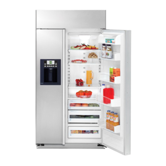
Profile 42" and 48" built-in side by side refrigerators
Hide thumbs
Also See for Profile PSB42LSRBV:
- Manual (105 pages) ,
- Owner's manual and installation instructions (88 pages) ,
- Installation instructions manual (64 pages)

Related Manuals for GE Profile PSB42LSRBV


Summary of Contents for GE Profile PSB42LSRBV
- Page 1 GE Consumer & Industrial TECHNICAL SERVICE GUIDE Profi le 42" and 48" Built-In Side by Side Refrigerators MODEL SERIES: PSB42LSRBV PSB42LGRWV PSB42LGRBV PSB48LSRBV PSB48LGRWV PSB48LGRBV PUB # 31-9125 11/04...
- Page 2 If grounding wires, screws, straps, clips, nuts, or washers used to complete a path to ground are removed for service, they must be returned to their original position and properly fastened. GE Consumer & Industrial Technical Service Guide Copyright © 2004 All rights reserved.
-
Page 3: Table Of Contents
Table of Contents 3-Way Valve ...........................36 Auger Motor ...........................27 Casters and Leveling ........................21 Components ..........................18 Component Locator Views ......................12 Component Resistance Values ......................8 Compressor ...........................35 Control Features ..........................10 Cube Motor and Cube Reed Switch ....................28 Defrost Cycles ..........................40 Diagnostic Mode ..........................52 Dispenser Control Panel ........................29 Dispenser Heater ...........................34 Dispenser Switch ...........................33... -
Page 4: Introduction
Introduction The new Profi le Built-In Side by Side refrigerator has the following features: • Separate freezer and fresh food evaporators are recessed into the machine compartment for increased effi ciency and interior space savings. • 3-Way valve directs refrigerant fl ow where needed. •... -
Page 5: The Installation Space
The water line and to allow for drawer removal. installed should be 1/4" O.D. copper tubing Four inch (4") minimum clearance is required or GE SmartConnect ™ tubing between the when door swing is adjusted to 90°. If the 90°... - Page 6 ALTERNATE ANTI-TIP INSTALL ANTI-TIP BRACKETS PRECAUTIONS ANTI-TIP WARNING: PRECAUTIONS SKIP THIS STEP WHEN USING ANTI-TIP The refrigerator is Top-Heavy and must be secured BRACKETS to prevent the possibility of tipping forward. All Profile built-in refrigerators are Top-Heavy. • Cut a 2" x 4" wood block 36" long, They must be secured to prevent the possibility and secure the block to of tipping forward.
- Page 7 CUSTOMIZATION BASICS: Framed Or Custom Panels Stainless Steel Wrapped Models 42" wide model - PSB42LSRBV Trimmed Models 42" wide models - PSB42LGRWV, PSB42LGRBV Stainless Steel Wrapped Refrigerators 3/4" Custom Panel Stainless Steel wrapped refrigerators have wrapped doors and grille panels, and beveled Door Handles edges.
-
Page 8: Component Resistance Values
Technical Data PSB42LGRBV, PSB42LGRWV, PSB42LSRBV PSB48LGRBV, PSB48LGRWV, PSB48LSRBV IMPORTANT SAFETY NOTICE DISCONNECT POWER CORD BEFORE SERVICING This information is intended for use by individuals IMPORTANT - RECONNECT ALL GROUNDING DEVICES possessing adequate backgrounds of electrical, All parts of this appliance capable of conducting electronic and mechanical experience. -
Page 9: Nomenclature
Nomenclature P S B 42 L G R A Door Type Brand/Product V - Visor Handle P - Profi le Trim W - White Disp Trim B - Black Disp Trim Style Engineering S - Side by Side A - Initial Design B - 1st Revision C - 2nd Revision Confi... -
Page 10: Control Features
Control Features ADJUST TEMPERATURE COLDER WARMER HOLD FOR REFRIGERATOR 37º F IS RECOMMENDED 3 SECS TO ACTIVATE COLDER WARMER LOCK FREEZER DISPLAY 0º F IS RECOMMENDED TEMP LIGHT ICE DISPENSER DOOR ALARM WATER CRUSHED CUBED QUICK ICE RESET FILTER HOLD 3 SECS The temperature controls are preset in the factory at 37°F for the refrigerator compartment and 0°F for the freezer compartment. -
Page 11: Icemaker Controls
Icemaker Controls To Use the Dispenser Select CUBED , CRUSHED Quick Ice or WATER When you need ice Press the glass gently against the middle in a hurry, press this QUICK ICE of the dispenser pad. button to speed up ice production. -
Page 12: Component Locator Views
Component Locator Views Machine Compartment Water Valve Condenser Drier 3-Way Valve* Main Power Switch *The 3-way valve is located behind the condenser front plate. Refrigerator (Bottom View, Drain Pan Removed) Door Closer Rear Leveler Water Lines Freezer Defrost Drain Tube Drain Pan Loop Fresh Food Defrost Drain Tube Rear Leveler... -
Page 13: Refrigeration Components
Refrigeration System Refrigeration Components Condenser Freezer Evaporator and Fan Fresh Food Evaporator and Fan Compressor 3-Way Valve Condenser Loop Drier Drain Pan Heater – 13 –... -
Page 14: Refrigerant Flow
or the fresh food and freezer evaporators, Refrigerant Flow refrigerant fl ows through the appropriate capillary tube and into the evaporator. As the high pressure The compressor compresses R134a refrigerant, liquid passes through the capillary and enters the raising its pressure and temperature. Refrigerant low pressure evaporator, it quickly expands and vapor is pumped out the compressor discharge, evaporates. -
Page 15: Freezer Section Cooling
FREEZER SECTION COOLING Muffler Condenser Fan Muffler Accumulator Freezer Fan Compressor Fresh Food Fan Freezer Fresh Food Condenser Evaporator Evaporator 3-Way Jumper Valve Tube Drier Capillary High Pressure Vapor Low Pressure Liquid Mix of Liquid and Vapor Mix of Liquid and Vapor High Pressure Liquid Low Pressure Vapor Note: The refrigerator will operate with the 3-way valve set for freezer only or set for fresh food and... -
Page 16: Evacuation And Charging Procedure
4. Open the ball valve. Recover the purge/ Evacuation and Charging Procedure sweep charge using the recovery pump and the refrigerator compressor until a 20-in. WARNING: vacuum is attained. Close the ball valve and • Before cutting or using a torch on refrigerant remove the recovery hose. - Page 17 Interior Airfl ow Freezer Air Flow Fresh Food Air Flow Warm Circulated Air Fresh Cold Air Note: The fans are extremely quiet. Check for airfl ow at the icemaker air duct in the freezer and the top tower vent in the fresh food section. Fans turn off when the doors are opened (DC door switches control operation) and delay 10 seconds before restarting when the doors are closed again.
-
Page 18: Components
Components Door Alignment Machine Compartment Access Door The freezer door is nonadjustable. The fresh The machine compartment access door is held in food door has an adjustment screw at the bottom place by 2 hinges and 2 gas shocks. hinge. Use a -in. - Page 19 Door Removal Door Gaskets WARNING: Use the appropriate safety equipment The fresh food and freezer doors have magnetic and lifting techniques. Two persons may be gaskets that create a positive seal to the front required for door removal. of the steel cabinet. The cabinet has magnets around the perimeter and center mullion under Caution: Use wood or a heavy plastic sheet to the front edge.
-
Page 20: Door Closer Assembly
2. Ensure the opening on the white nylon Door Closer Assembly support faces towards the inside of the cabinet. Each door is equipped with a door closer assembly that provides a smooth closing action and prevents the door from being slammed shut. The assembly is connected to the bottom hinge. -
Page 21: Casters And Leveling
Drain Pan Casters and Leveling The drain pan can be removed for cleaning Leveling is provided by 2 adjustable rear levelers purposes. and 2 front leveling legs. The unit has 4 fi xed casters that are used to position the refrigerator. Drain pan removal: When adjusting the rear levelers, turn the 1. -
Page 22: Power Control Board (Pcb)
Power Control Board (PCB) The PCB housing is attached to the rear wall of the machine compartment by 2 Phillips-head screws. The PCB is enclosed inside a housing and mounted on the right side of the machine compartment behind the terminal block panel. Noise Filter The noise fi... -
Page 23: Control Board Connector Locator
Control Board Connector Locator Temperature Control & Display 3-Way Valve CN71 FZ Defrost * CN72 CN90 CN50 CN30 FF Defrost ** CN71 CN50 CN30 CN72 CN90 CN31 CN31 Dispenser Heater External Thermistor CN02 Pin 11 Neutral (from noise filter) CN70 CN70 Duct Door Motor Dispenser Water Valve... -
Page 24: Terminal Block Panel
Terminal Block Panel The terminal block panel is located on the right side of the machine compartment and attached to the PCB housing cover. The terminal block consists of AC and DC wire harness connectors. To access the wire harness connectors, remove the 4 Phillips-head screws that hold the front cover in place. - Page 25 Connector Description DC CONNECTIONS AC CONNECTIONS DESCRIPTION WIRE COLOR DESCRIPTION WIRE COLOR Condenser Fan Feedback L1 (Switched thru Master Switch) Black Condenser Fan VDC Light Blue Neutral (Switched thru Master Switch) Condenser Fan Common Gray 3-Way Valve FZ Defrost (Switched L1) Brown 3-Way Valve Black...
-
Page 26: Icemaker Fill Tube And Heater
To remove the icemaker: Ice Bin and Icemaker Remove the ice bin. Remove 2 front screws Ice Bin that hold the ice bin shelf in place. The ice bin holds approximately 7 pounds of ice, equivalent to about 230 cubes. 2. -
Page 27: Compressor
3. In the machine compartment, remove the Auger Motor 2 screws from the fi ll tube cover (located beneath the water valve to the left of The auger motor is mounted to the ice bin shelf. compressor). To access the auger motor: 1. -
Page 28: Cube Motor And Cube Reed Switch
To check the cube reed switch: Cube Motor and Cube Reed Switch 1. Select on the ice dispenser control CUBED The cube motor replaces the cube solenoid panel, then press the dispenser pad to close assembly and is mounted to the ice container the switch. -
Page 29: Dispenser Control Panel
Testing the Dispenser Control Pads Dispenser Control Panel Run the HMI Self-Test 0 6 (see Service The dispenser control panel contains the control ). If any portion of the test fails, the Diagnostics module and room ambient thermistor. The panel control module pads can be tested at the CN04 is available in black or white. -
Page 30: Ice Dispenser
The icemaker water line is routed from the water Ice Dispenser valve, through the machine compartment, and to the icemaker fi ll tube. The water tank line is The water, crushed ice, and cubed ice functions routed from the water valve, through the back are controlled by the power control board (PCB). - Page 31 To replace the water valve: Approximate water temperature by the glass: Note: Some water may leak from the • Room Ambient at 76°F (24°C). water supply line and valve when they are • 8-ounce glass. disconnected. • One-minute interval between dispensing 1.
-
Page 32: Duct Door Assembly
The duct door motor switches are held in place by Duct Door Assembly 2 tabs. Duct Door The dispenser control panel must be removed before removing the duct door. Insert a fl at-blade screwdriver between the duct door (top right corner) and the switch housing. Use the screwdriver to slide the door to the left, until the hinge pin is free. -
Page 33: Dispenser Switch
3. Slide motor assembly to the left to clear the Dispenser Switch rear mounting tabs. The dispenser switch pad must be removed to 4. Pull the motor forward while rotating it access the dispenser switch. Insert a fl at-blade clockwise. screwdriver into the bottom slot of the dispenser switch pad and lift up. -
Page 34: Dispenser Heater
Dispenser Heater Main Switch The dispenser cavity heater is non serviceable. If The main switch is mounted to a bracket at the defective, the freezer door must be replaced. front of the machine compartment. The main switch opens both the line voltage and neutral The amount of time the heater is energized is side to the refrigerator. -
Page 35: Heat Exchanger
To check power to the main switch, check for Compressor Circuit 120 VAC between the black and red wires on the CN08 connector shown below. BLACK PURPLE COMP BLUE LIGHT BLUE LIGHT BLUE OVER-LOAD PROTECTOR Refrigerant Charge The refrigerant used in the sealed system is R134a. -
Page 36: Drier
Muffl ers 3-Way Valve The sealed system has 2 muffl ers to reduce The 3-way valve directs the refrigerant fl ow to noise, one in the suction line and one in the the two evaporators as needed, and is controlled compressor discharge line. - Page 37 Testing Replacement To test whether the 3-way valve is receiving a When replacing the 3-way valve, note the red signal from the power control board: sleeve on the valve tube. This tube connects to the freezer capillary. The corresponding freezer 1.
-
Page 38: Doors
The DC switches provide “door open” information Door Switches to the power control board (PCB). The refrigerator is equipped with an AC and a DC Note: The fans turn off when the doors are switch above each door. The switches are located opened (DC door switches control operation) inside the machine compartment. -
Page 39: Thermistors
Freezer Evaporator Thermistor Thermistors The evaporator thermistor is mounted in a copper The main control board uses input from 5 sleeve on the top, right corner of the evaporator. thermistors: Check for thermistor resistance (see Thermistor • Ambient ) by disconnecting the harness from CN06 Chart •... -
Page 40: Defrost Cycles
For example, after approximately 10 accumulated Defrost Cycles hours of compressor running time, the freezer evaporator will have gone through one defrost The refrigerator incorporates two different cycle, and the fresh food evaporator will have methods of defrost. Once the compressor has gone through two defrost cycles. -
Page 41: Fans
The fresh food evaporator fan motor supply Fans voltage can be checked at CN05 on the terminal block. When the power control board (PCB) All 3 fans (condenser, freezer, and fresh food) are is energizing the fan, check for approximately variable-speed DC fans. - Page 42 The 3-bladed fan can be removed without 6. Pull the cabinet wiring down as shown in the removing the complete fan assembly. photo below. Carefully pull the condenser fan assembly out of the machine compartment. The fan rotates counterclockwise as viewed from the motor shaft end.
-
Page 43: Freezer Heater Testing
Freezer Heater Testing Fresh Food Heater Testing The freezer evaporator defrost heater, suction The fresh food evaporator defrost heater, line drain pan heater, and the evaporator drain evaporator drain pan heater, and icemaker fi ll pan/drain tube heater are in a parallel circuit. tube heater are in a parallel circuit. -
Page 44: Drain Pan
6. Remove the rear air duct cover. Freezer Evaporator Assembly 7. Remove the 2 Phillips-head screws from the The freezer evaporator assembly consists of an suction line drain pan and heater assembly. evaporator, defrost and drain heaters, defrost Disconnect the associated wiring. safety thermostat, thermistor, and fan assembly. - Page 45 9. Remove the 2 Phillips-head screws that hold 11. Remove the 2 Phillips-head screws that hold the freezer plug cover in place, then remove the freezer evaporator assembly housing in the freezer plug cover. place. Assembly Housing Freezer Plug Cover 12.
- Page 46 Freezer Evaporator Fan Assembly Note: When installing the fan assembly, ensure that the housing lip inserts into the channel. The freezer evaporator fan assembly consists of a 2-speed DC fan motor, blower wheel, and housing. It is mounted on top of the evaporator. To remove the freezer evaporator fan assembly: Channel...
-
Page 47: Freezer Evaporator Components
WARNING: The evaporator fi ns are very sharp. Freezer Evaporator Components Wear Kevlar gloves when handling. To access the freezer evaporator components: 5. Remove the single Phillips-head screw at the corner of the evaporator. 1. Access the freezer evaporator assembly. (See Freezer Evaporator Assembly. -
Page 48: Fresh Food Evaporator Assembly
4. Remove the 4 Phillips-head screws that hold Fresh Food Evaporator Assembly the refrigerator suction line drain assembly in place. Remove the assembly. The fresh food evaporator assembly consists of an evaporator, defrost and drain heaters, bimetal defrost safety thermostat, thermistor, and evaporator fan assembly. - Page 49 8. Lower the evaporator assembly into the fresh Fresh Food Evaporator Fan Assembly food compartment. To remove the fresh food evaporator fan assembly: 1. Access the fresh food evaporator assembly. (See Fresh Food Evaporator Assembly 2. The fan assembly is attached to the evaporator assembly with 4 Phillips-head screws (2 on each side of the fan assembly).
-
Page 50: Fresh Food Evaporator Components
Fresh Food Evaporator Fresh Food Evaporator Components To access the fresh food evaporator: To access the fresh food evaporator components: 1. Access the fresh food evaporator assembly. (See Fresh Food Evaporator Assembly. 1. Access the fresh food evaporator assembly. (See Fresh Food Evaporator Assembly. -
Page 51: Main Switch
6. Carefully cut and remove the insulation on the Replacing the Freezer or Fresh Food suction line and capillary tubing to expose the Evaporator solder joints. The freezer evaporator can be replaced as a complete unit, including the defrost components and fan assembly, or it can be replaced as an individual component. -
Page 52: Service Diagnostics
Service Diagnostics 4. Once the displays indicate a test mode, press Diagnostic Mode any pad on the temperature board overlay, 1. To enter the diagnostic mode, the temperature other than the pads, to enter COLDER WARMER that mode. display must be lit up. If the temperature display is not lit, press any pad on the overlay. -
Page 53: Test Mode Chart
Test Mode Chart FZ Display FF Display Mode Comments Showroom Mode See Note #1. Do Not Use Do Not Use Do Not Use Do Not Use HMI Self-Test See Note #2. Control and Sensor Self-Test See Note #3. Do Not Use Dispenser Recess Heater Test Turn the dispenser heater ON for 30 seconds. - Page 54 Note #3 (Control and Sensor System Self-Test) This test does a check on all thermistors, fans, and defrost circuits. The thermistor test will display pass, open or shorted. The fan and defrost tests will display pass or fail. Once this test is invoked, the test mode will stop fl...
-
Page 55: Troubleshooting Notes
Troubleshooting Notes Problem Action The HMI may display 80°F (27°C) if the Refrigerator HMI displays a temperature of 80°F refrigerator thermistor (air) is either open or (27°C), even though the temperature in the shorted. Run service diagnostics (Test 0 7) to refrigerator section is correct. -
Page 56: Schematics
Schematics PSB42LGRBV PSB42LGRWV PSB42LSRBV PSB48LGRBV PSB48LGRWV PSB48LSRBV AC Section CHOKE (Part 1) – 56 –... - Page 57 Schematics (Part 2) DC Section – 57 –...
-
Page 58: Illustrated Parts
Illustrated Parts PSB42LSRBV Shown – 58 –... - Page 59 PSB42LSRBV Shown – 59 –...
- Page 60 PSB42LSRBV Shown – 60 –...
- Page 61 PSB42LSRBV Shown – 61 –...
- Page 62 PSB42LSRBV Shown – 62 –...
- Page 63 PSB42LSRBV Shown – 63 –...
- Page 64 PSB42LSRBV Shown – 64 –...
- Page 65 PSB42LSRBV Shown – 65 –...
- Page 66 PSB42LSRBV Shown – 66 –...
- Page 67 PSB42LSRBV Shown – 67 –...
- Page 68 VIEW NUMBER CATALOG NUMBER DESCRIPTION QUANTITY 0001 31-46170 INSTALLATION INSTRUCTION 0001 31-51582 MINI MANUAL 0001 49-60296-1 USE & CARE MANUAL 0100 WR78X11086 DOOR ASM FZ SS 0101 WR02X11890 TUBE-WATER LINE A 0103 WR23X10396 SWITCH-MICRO 0104 WR02X11891 CAP-TUBE WATER LINE 0105 WR02X11892 CAP-CHUTE ICE 0106...
- Page 69 VIEW NUMBER CATALOG NUMBER DESCRIPTION QUANTITY 0304 WR60X10176 MOTOR FAN ASM FZ 0305 WR17X11730 CASE EVAP FZ FRONT 0306 WR17X11731 EVAP CASE REAR FZR 0308 WR02X11871 SCREW-TAPPING 0309 WR50X10056 THERMISTOR - FZ EVAP 0310 WR50X10057 THERMOSTAT DEFROST FZ 0311 WR02X11872 BRACKET THERMOSTAT FZ 0312 WR51X10082...
- Page 70 VIEW NUMBER CATALOG NUMBER DESCRIPTION QUANTITY 0608 WR50X10059 THERMISTOR FF EVAP 0609 WR50X10060 THERMOSTAT DEFROST FF 0611 WR02X11885 DRAIN TROUGH ASM FF 0616 WR50X10061 THERMISTOR FF 0617 WR23X10394 HARNESS UPPER LIGHTS FF 0618 WR17X11741 COVER DUCT ASM FF 0619 WR23X10395 HARNESS LOWER LIGHTS FF 0621 WR17X11742...
- Page 71 VIEW NUMBER CATALOG NUMBER DESCRIPTION QUANTITY 0931 WR02X11925 SUPPORT DRAIN PAN REAR 0932 WR17X11753 CONDENSER SUPPORT ASM 0935 WR17X11754 DRAIN PAN 0936 WR17X11755 PANEL TOE KICK 0937 WR02X11911 COVER-WATER LINE 0938 WR01X10460 SCREW-MACHINE 0939 WR01X10461 SCREW-TAPPING 0940 WR01X10462 BOLT 10MM 0945 WR02X11947 SUPPORT DRAIN PAN FRONT...
-
Page 72: Warranty
Any part of the refrigerator which fails due to a defect in materials or workmanship. From the date of the During this full two-year warranty, GE will also provide, free of charge, all labor and in-home original purchase service to replace the defective part.