Table of Contents
Advertisement
Quick Links
Chapter 1
INTRODUCTION
The ATX BX2 mainboard is a high-performance personal computer
mainboard based on the Pentium
TM
supports MMX
The mainboard uses the highly integrated Intel
support the PCI/ISA and Green standards, and to provide the Host/AGP
®
bridge. The Intel
such as ACPI (Advanced Configuration and Power Interface). The ACPI
provides more Energy Saving Features for the OSPM(OS Direct Power
Management) function. The Intel
transfer rate by supporting Ultra DMA/33 IDE that transfers data at the rate
of 33MB/s.
The mainboard also supports the System Hardware Monitor Controller as an
optional function. This function includes: CPU /power supply/chassis fan
revolution detect, CPU/system voltage monitor, system temperature monitor,
and chassis intrusion detect(optional).
®
II processor. The Pentium
(Multimedia Extension) technology.
82371EB chipset integrates all system control functions
®
82371EB chipset also improves the IDE
®
82443BX AGP chipset to
1-1
®
II processor
Advertisement
Table of Contents

Related Manuals for MSI ATX BX2


Summary of Contents for MSI ATX BX2
- Page 1 Chapter 1 INTRODUCTION The ATX BX2 mainboard is a high-performance personal computer ® ® mainboard based on the Pentium II processor. The Pentium II processor supports MMX (Multimedia Extension) technology. ® The mainboard uses the highly integrated Intel 82443BX AGP chipset to support the PCI/ISA and Green standards, and to provide the Host/AGP ®...
-
Page 2: Mainboard Features
1.1 Mainboard Features ® Slot 1 for Pentium II processor. Supports 233MHz, 266MHz, 300MHz, 333MHz, 400MHz, and faster. Core/Bus ratios are x2, x2.5, x3, x3.5, x4, x4.5, x5, x5.5, x6 and higher. Switching Voltage Regulator On-board switching mode DC-DC Step Down Regulator. ®... - Page 3 On-Board IDE ® An IDE controller on the Intel 82371EB PCI chipset provides IDE HDD/ CD-ROM with PIO, Bus Master and Ultra DMA/33 operation modes. Can connect up to four IDE devices. On-Board Peripherals On-Board Peripherals include: - 1 floppy port supports 2 FDD with 360K, 720K, 1.2M, 1.44M and 2.88Mbytes.
- Page 4 Keyboard Connector ® ® PS/2 keyboard interface and PS/2 mouse interface. Dimension ATX Form Factor: 30cm(L) x 18.6cm(W) x 4 layers PCB. ® Double deck I/O connectors, compatible with Intel Venus Mainboard. Mounting 6 mounting holes. Other Features Keyboard Password Wake-Up.(reserved) LAN Wake-Up.
-
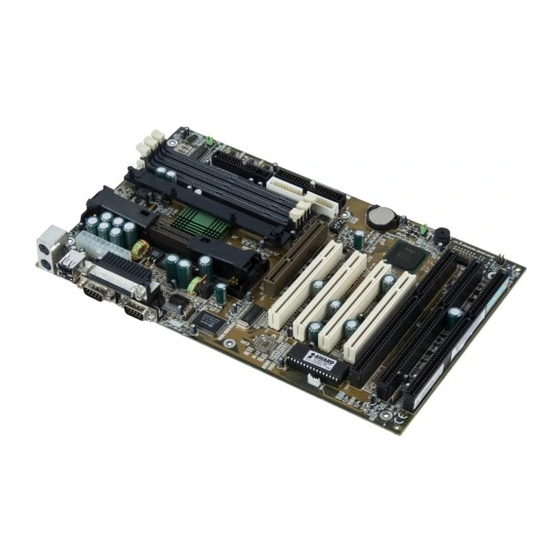
Page 5: Mainboard Layout
1.2 Mainboard Layout PSFAN1 (optional) Top: mouse JVSB CPUFAN1 Bottom: JRMS1 keyboard Top: Port 1 Bottom: Port 2 Top: LPT Bottom: COM A COM B FW82443BX JSOR1 (optional) AGP Slot PCI SlOT 1 BATT PCI SLOT 2 PCI SLOT 3 FW82371EB JBAT1 JMODE1... -
Page 6: Hardware Installation
Chapter 2 HARDWARE INSTALLATION ® ® The mainboard operates with Intel Pentium II processor. The mainboard used a CPU Slot called Slot 1 for easy CPU installation. To set the proper speed for the CPU, you should first check your mainboard. There are two kinds of mainboard: CPU Plug &... -
Page 7: Cpu Installation Procedures
2.1-1 CPU Installation Procedures ® Different kinds of Pentium II processor that is currently used: the OEM ® version, the Boxed version, and Celeron . OEM Pentium II Processor has ® no Heat Sink, Fan and Heat Sink Support, the Boxed Pentium II Processor is provided with Heat Sink w/ fan and Heat Sink Support, while the Celeron... - Page 8 HSSBASE through the fins on the ATX heatsink. ® **Heat Sink w/ fan - Heat Sink that can be attached to the Pentium processor with metal clip. Note: * Provided by MSI mainboard. ** Provided by Special request. HSSBASE HSSPIN RMAM...
- Page 9 Step 1: Insert the Retention Mechanism Attach Mount at the bottom of the mainboard. Step 2: Install the Retention Mechanism. Look for the key on Slot 1, and match it with the Notch Key on the Retention Mechanism for proper direction. Then, attach the Retention Mechanism to the Retention Mechanism Attach Mount.
- Page 10 Step 3: Install the Heat Sink Support Base. Look for the Two holes across Slot 1, and match it with the Two legs of the Heat Sink Support Base for the proper direction. Take note that one hole/leg is bigger than the other. The Four top pins of the Heat Sink Support Base should also be oriented towards Slot 1.
- Page 11 Step 5: Install the Heat Sink with Fan to the Processor. Push down the metal clips, so that they are in line with the back of the Heat Sink. Be careful, so as not detach the metal clips from the Heat Sink.
- Page 12 Step 6: Install the Processor. Unlock the Processor by pushing in the Processor Locks. Insert the Processor like inserting a PCI or an ISA card. Step 7: Lock the Processor Locks. Secure the CPU by pulling the Processor Locks out.
- Page 13 Step 8: Install the Heat Sink Support Top Bar. Push the Heat Sink Support Top Bar to the Heat Sink Support Base, Until you hear a “click” sound. Check for a perfect fit. Heatsink Support Top The installation is now complete.
- Page 14 ® B. Boxed Pentium II Processor Installation Procedures ® The Boxed Pentium II Processor has a built- in Fan and Heat Sink. It also has a Heat Sink Support. So if you’re going to use a Boxed Pentium Processor, all you need is the Retention Mechanism. Step 1: Insert the Retention Mechanism Attach Mount at the bottom of the mainboard.
- Page 15 Step 3: Install the Heat Sink Support Base. Look for the 2 holes across Slot 1, and match it with the 2 Heat Sink Support Base. Take note that one hole/base is bigger than the other. Retention Mechanism Notch Hole PC-3742 Heat Sink Support Base...
- Page 16 Step 4: Install the Heat Sink Support. Attach the 2 Heat Sink Supports to the sides of the Processor. These Heat Sink Supports will fit in any direction, so be sure that the Heat Sink Support Locks are oriented outwards for the proper direction. ®...
- Page 17 Step 5: Unlock the Processor Locks and Heat Sink Support Locks. Push in the Processor Locks. Open the Heat Sink Support Locks. Processor Lock Heatsink Support Lock PC-3744 Step 6: Insert the Processor like inserting a PCI or an ISA card. 2-12...
- Page 18 PC-3745 Step 7: Lock the Processor Locks and Heat Sink Support Locks Secure the CPU by pushing out the Processor Locks. Close the Heat Sink Support Locks. The installation is now complete. 2-13...
- Page 19 C. OEM Celeron Processor Installation Procedures Step 1: Insert the Retention Mechanism Attach Mount at the bottom of the mainboard. Step 2: Install the Retention Mechanism. Look for the key on Slot 1, and match it with the Notch Key on the Retention Mechanism for proper direction.
- Page 20 Step 3: Install the Heat Sink to the Processor. Celeron Heat Sink processor plastic Clip Push down the plastic clips, so that they are in line with the hole on the processor. Check for perfect fit. Step 4: Install the Processor. Insert the Processor like inserting a PCI or an ISA card.
-
Page 21: Cpu Core Speed Derivation Procedure
2.1-2 CPU Core Speed Derivation Procedure 1. The DIP Switch SW1 (1, 2, 3, and 4) is used to set the Core/Bus (Fraction) ratio of the CPU. The actual core speed of the CPU is the Host Clock Frequency multiplied by the Core/Bus ratio. For example: CPU Clock 66MHz Core/Bus ratio... -
Page 22: Cpu Speed Setting
2.1-3 CPU Speed Setting To adjust the speed of the CPU, you must know the specification of your CPU (always ask the vendor for CPU specification). a. 66MHz CPU Bus Frequency Type 200MHz 233MHz 266MHz 300MHz 333MHz ® ® Table 2.1 200 ~ 333MHz Intel Pentium II processor b. - Page 23 2.1-4 Fan Power Connectors: CPUFAN1/PSFAN1/SYSFAN1 These connectors support system cooling fan with +12V. It supports three pin head connector. When connecting the wire to the connector, always take note that the red wire is the positive and should be connected to the +12V, the black wire is Ground and should be connected to GND.
-
Page 24: Voltage Setting
This jumper is for setting the voltage of the Flash ROM BIOS. JMODE1 Voltage Setting JMODE1 +12V PWD VCC +12V PWD VCC +12V (default) ® Note: a. Short 1-2 pin, if you’re using Intel or MXIC flash memory and you want to flash the ROM data. b. - Page 25 A battery must be used to retain the mainboard configuration in CMOS RAM. If you use the on-board battery, you must short 1-2 pins of JBAT1 to keep the CMOS data. JBAT1 Clear Data Keep Data Note: To short the CMOS data, turn off the system and unplug the power cord for about 10 seconds afterwhich, move jumper cap from pin 1-2 to 2-3 and back to 1-2 pin position.
-
Page 26: Memory Bank Configuration
2.4-1 Memory Bank Configuration The mainboard supports a maximum of 384MB (8M x 8) or 768MB (16M x 4) registered DIMM only. It provides three 168-pin unbuffered DIMMs (Double In-Line Memory Module) sockets. It supports 8 MB to 256 Mbytes DIMM memory module. -
Page 27: Memory Installation Procedures
2.4-2 Memory Installation Procedures A. How to install a DIMM Module Single Sided DIMM Double Sided DIMM 1. The DIMM slot has a two Notch Key “VOLT and DRAM”, so the DIMM memory module can only fit in one direction. 2. -
Page 28: Memory Population Rules
2.4-3 Memory Population Rules 1. Supports SDRAM DIMM. 2. Supports unbuffered DIMM. 3. To operate properly, at least one 168-pin DIMM module must be installed. 4. This mainboard supports Table Free memory, so memory can be installed on DIMM1, DIMM2, or DIMM 3 in any order. 5. - Page 29 The Power Switch, Reset Switch, Key Lock, Power LED, Speaker and HDD LED are all connected to the JFP1 connector block. Keylock Power Speaker Power Switch Reset Switch JFP1 2-24...
-
Page 30: Power Switch
2.5-1 Power Switch Connect to a 2-pin push button switch. This switch had the same feature with JRMS1. 2.5-2 Reset Switch Reset switch is used to reboot the system rather than turning the power ON/ OFF. Avoid rebooting while the HDD LED is lit. You can connect the Reset switch from the system case to this pin. - Page 31 The mainboard also provides a standard floppy disk connector FDC that supports 360K, 720K, 1.2M, 1.44M and 2.88M floppy disk types. This connector support the provided floppy drive ribbon cables. 2-26...
- Page 32 The mainboard has a 32-bit Enhanced PCI IDE Controller that provides PIO mode 0~4, Bus Master, and Ultra DMA/33 function. It has two HDD connectors IDE1 (primary) and IDE2 (secondary). You can connect up to four hard disk drives, CD-ROM, 120MB Floppy (reserved for future BIOS) and other devices to IDE1 and IDE2.
-
Page 33: Atx 20-Pin Power Connector: Jpwr1
2.8-1 ATX 20-pin Power Connector: JPWR1 This connector supports the power button on-board. Using the ATX power supply, functions such as Modem Ring Wake-Up and Soft Power Off are supported by this mainboard. This power connector supports instant power on function which means that system will boot up instantly when the power connector is inserted on the board. - Page 34 2.8-2 Remote Power On/Off Switch: JRMS1 Connect to a 2-pin push button switch. During OFF state, press once and the system turns on. During ON stage, push once and the system goes to sleep mode: pushing it more than 4 seconds will change its status from ON to OFF.
- Page 35 The mainboard provides one 5-pin infrared (IR1) connector for IR modules. This connector is for optional wireless transmitting and receiving infrared module. You must configure the setting through the BIOS setup to use the IR function. FIR and Consumer IR are reserved functions. Description IRRX IRTX...
- Page 36 The mainboard has two 9-pin male DIN connectors for serial ports COM A and COM B. These two ports are 16550A high speed communication ports that send/receive 16 bytes FIFOs. You can attach a mouse or a modem cable directly into these connectors. 1 2 3 4 5 6 7 8 9 COM A...
- Page 37 The mainboard provides a 25 pin female centronic connector for LPT. A parallel port is a standard printer port that also supports Enhanced Parallel Port(EPP) and Extended capabilities Parallel Port(ECP). See connector and pin definition below: 13 12 11 10 9 8 7 6 5 4 3 2 1 25 24 23 22 21 20 19 18 17 16 15 14 PIN DEFINITION SIGNAL...
- Page 38 ® The mainboard provides a standard PS/2 mouse mini DIN connector for ® ® attaching a PS/2 mouse. You can plug a PS/2 mouse directly into this connector. The connector location and pin definition are shown below: Pin5 Mouse Clock Pin6 Pin3 Pin4...
- Page 39 The mainboard provides a UHCI(Universal Host Controller Interface) Universal Serial Bus root for attaching USB devices like: keyboard, mouse and other USB devices. You can plug the USB device directly to this connector. USB Port 1 1 2 3 4 USB Port 2 SIGNAL -Data0...
- Page 40 Attach a power saving switch to JGS1. When the switch is pressed, the system immediately goes into suspend mode. Press any key and the system wakes up. JGS1 2-35...
- Page 41 JGL1 can be connected with LED. This will lit while the system is in suspend mode. JGL1 2-36...
- Page 42 The JVSB jumper is for setting keyboard power. This function is provided by keyboard and PS/2 mouse Wake-up function. JVSB 5V_Standby (default) 2-37...
- Page 43 The mainboard supports two kinds of system boot up: the Boot-Up by switch and the Immediate Boot-Up. With the Boot-Up by Switch, the system will boot up only when the power on switch is pressed. For Immediate Boot- Up, the system will boot up instantly when the power connector is connected into the system.
- Page 44 The mainboard provides a distributed DMA connector for PCI sound card ® with this feature, such as Creative PCI 3D sound card. Serial Interrupt Request Signal Signal DMA Grand Signal 2-39...
- Page 45 The JMDM1 connector is for used with Modem add-on card that supports the Modem Wake Up function. JMDM1 SIGNAL MDM_WAKEUP 5VSB Note: Modem wake-up signal is active “low”. Note: To be able to use this function, you need a power supply that provide enough power for this feature.
- Page 46 The JWOL1 connector is for use with LAN add-on cards that supports Wake Up on LAN function. JWOL1 SIGNAL 5VSB MP_WAKEUP Note: LAN wake-up signal is active “high”. Note: To be able to use this function, you need a power supply that provide enough power for this feature.
- Page 47 This is used to check the CPU temperature. The JSOR1 is a sensor that is placed near the processor heatsink. This will monitor the CPU temperature. JSOR1 2-42...
- Page 48 This connector is connected to 2-pin connector chassis switch. If the Chassis is open, the switch will be short. The system will record this status. To clear the warning, you must enter the BIOS settting and clear the status. 2-43...
-
Page 49: Award Bios Setup
® Chapter 3 AWARD BIOS SETUP ® Award BIOS ROM has a built-in Setup program that allows users to modify the basic system configuration. This type of information is stored in battery-backed RAM (CMOS RAM), so that it retains the Setup information when the power is turned off. -
Page 50: Status Page Setup Menu/Option Page Setup Menu
® Power on the computer and press <Del> immediately to allow you to enter Setup. The other way to enter Setup is to power on the computer. When the below message appears briefly at the bottom of the screen during the POST (Power On Self Test), press <Del>... -
Page 51: Bios Features Setup
® ® Once you enter Award BIOS CMOS Setup Utility, the Main Menu (Figure 1) will appear on the screen. The Main Menu allows you to select from ten setup functions and two exit choices. Use arrow keys to select among the items and press <Enter>... -
Page 52: Chipset Features Setup
® Chipset Features Setup This setup page includes all the items of chipset special features. Power Management Setup This category determines the power consumption for system after setting the specified items. Default value is Disable. PCI Configuration Setup This category specifies the IRQ level for PCI and ISA devices. Supervisor Password/User Password Change, set or disable password. - Page 53 ® The items in Standard CMOS Setup Menu are divided into 10 catego- ries. Each category includes no, one or more than one setup items. Use the arrow keys to highlight the item and then use the <PgUp> or <PgDn> keys to select the value you want in each item.
-
Page 54: Primarymaster/Primaryslave Secondarymaster/Secondary Slave
® Date The date format is <day><month> <date> <year>. Day of the week, from Sun to Sat, determined by BIOS. Read-only. month The month from Jan. through Dec. date The date from 1 to 31 can be keyed by numeric function keys. - Page 55 ® If the controller of HDD interface is ESDI, the selection shall be “Type 1”. If the controller of HDD interface is SCSI, the selection shall be “None”. If the controller of HDD interface is CD-ROM, the selection shall be “None”.
- Page 56 ® ROM PCI/ISA BIOS (2A59IM4A) BIOS FEATURES SETUP AWARD SOFTWARE, INC. Virus Protection By : None Video BIOS Shadow :Enabled CPU Internal Cache : Enabled C8000-CBFFF Shadow :Disabled External Cache : Enabled CC000-CFFFF Shadow :Disabled CPU L2 Cache ECC Checking: Enabled D0000-D3FFF Shadow :Disabled Quick Power on Self Test : Disabled...
-
Page 57: Cpu Internal Cache
® None No warning message to appear when anything (default) attempts to access the boot sector or hard disk partition table. Both/Trend/ Activates automatically when the system boots Award up causing a warning message to appear when anything attempts to access the boot sector of hard disk partition table. -
Page 58: Boot Sequence
® Boot From LAN First During Enabled, If there’s a LAN card onboard the priority from booting will be from the LAN. Boot Sequence This category determines which drive the computer searches first for the disk operating system (i.e., DOS). The settings are A,C,SCSI/C,A,SCSI/ C,CD-ROM,A/CD-ROM,C,A/D,A,SCSI/E,A,SCSI/F,A,SCSI/SCSI,A,C/ SCSI,C,A/C only. -
Page 59: Security Option
® Security Option This category allows you to limit access to the system and Setup, or just to Setup. System The system will not boot and access to Setup will be denied if the correct password is not entered at the prompt. Setup(default) The system will boot, but access to Setup will be denied if the correct password is not entered... -
Page 60: Video Bios Shadow
® Report No FDD For WIN 95 ® This function is only use when you are testing SCT for Windows Logo. Video BIOS Shadow Determines whether video BIOS will be copied to RAM for faster execution. Video shadow will increase the video performance. Enabled (default) Video shadow is enabled Disabled... - Page 61 ® The Chipset Features Setup option is used to change the values of the chipset registers. These registers control most of the system options in the computer. Choose the “CHIPSET FEATURES SETUP” from the Main Menu and the following screen will appear. ROM PCI/ISA BIOS(2A59IM4A) CMOS SETUP UTILITY CHIPSET FEATURES SETUP...
-
Page 62: System Bios Cacheable
® SDRAM Configuration by Choose SPD, the SDRAM time will load from the DIMM EEPROM value. Choose manual, the value will be set by SDRAM Ras-to-CAS Delay, SDRAM RAS Precharge Time, and SDRAM CAS Latency Time. The settings are SPD and Manual. If the DIMM is without EEPROM or over CPU clock, then set this item to Manual. -
Page 63: Video Bios Cacheable
® Video BIOS Cacheable Select Enabled allows caching of the system BIOS ROM at C0000h- F7FFFh, resulting in better video performance. However, if any program writes to this memory area, a system error may result. Enabled Video BIOS access cached Disabled Video BIOS access not cached Video RAM Cacheable... -
Page 64: Delayed Transaction
® Delayed Transaction The chipset has an embedded 32-bit posted write buffer to support delay transactions cycles. Select Enabled to support compliance with PCI specification version 2.1. The settings are Enabled or Disabled. AGP Aperture Size (MB) Select the size the of the Accelerated Graphics Port (AGP) aperture. The aperture is a portion of the PCI memory address range dedicated for graphics memory address space. -
Page 65: Power Management
® The Power Management Setup will appear on your screen like this: ROM PCI/ISA BIOS (2A59IM4A) POWER MANAGEMENT SETUP AWARD SOFTWARE, INC. Restore AC/Power Loss :Power On ACPI Function :Enabled IRQ 8 Clock Event :Disabled Power Management :User Define PM Control by APM :Yes ** Reload Global Timer Events ** Video Off Method... -
Page 66: Acpi Function
® ACPI Function During Enabled, this will support ACPI function. Power Management Disable Global Power Management will be disabled. User Define Users can configure their own power management. Min Saving Pre-defined timer values are used such that all timers are in their MAX value. Max Saving Pre-defined timer values are used such that all timers are in their MIN value. -
Page 67: Video Off After
® Video Off After The settings are N/A, Standby, Doze, or Suspend. This option is for choosing the setting in which the monitor will turn off. Always turn on. Doze During Doze mode, the monitor will be turned off. Standby During Standby mode, the monitor will be turned off. -
Page 68: Standby Mode
® Standby Mode Disable System will never enter STANDBY mode. Defines the continuous idle time before the 1 Min/2 Min/ system enters STANDBY mode. 4 Min/6 Min/ If any item defined in the options of “Power 8 Min/10 Min/ Down and Resume events” is enabled & active, 20 Min/30 Min/ STANDBY timer will be reloaded. - Page 69 ® Throttle Duty Cycle This option will determine how much power will be used by the CPU , if the system goes into suspend mode. VGA Active Monitor During Enabled, if there’s no activity in the monitor screen the system will go into Power Saving Mode. During Disabled, the system will go into Power Saving Mode, whether there is activity in the monitor screen or not.
-
Page 70: Resume By Alarm
® Resume by Alarm This function is for setting date and time for your computer to boot up. During Disabled, you cannot use this function. During Enabled, choose the Date and Time Alarm: Date(of month) Alarm You can choose which month the system will boot up. - Page 71 ® IRQ 8 Clock Event IRQ[3-7,9-15], NMI : Enabled Primary IDE 0 : Enabled Primary IDE 1 : Disabled Secondary IDE 0 : Disabled Secondary IDE 1 : Disabled Floppy Disk : Enabled Serial Port : Enabled Parallel Port : Enabled During Enabled, if any interrupt event occurs, the system will wake- up from suspend mode.
-
Page 72: Pnp Os Installed
® You can manually configure the PCI Device’s IRQ. The following pages tell you the options of each item & describe the meanings of each options. ROM PCI/ISA BIOS (2A69HM4D) PNP/PCI CONFIGURATION SETUP AWARD SOFTWARE, INC. PnP OS Installed Assign IRQ for VGA : Enabled Resources Controlled By :Manual... -
Page 73: Resources Controlled By
® Resources Controlled By By Choosing “Auto”, the system BIOS will detect the system resource and automatically assign the relative IRQ and DMA Channel for each peripheral. By Choosing “Manual”(default), the user will need to assign IRQ & DMA for add-on cards. Be sure that there is no conflict for IRQ/DMA and I/ O ports. -
Page 74: Assign Irq For Vga
® IRQ-15 assigned to : PCI/ISA PnP DMA-0 assigned to : PCI/ISA PnP DMA-1 assigned to : PCI/ISA PnP DMA-3 assigned to : PCI/ISA PnP DMA-5 assigned to : PCI/ISA PnP DMA-6 assigned to : PCI/ISA PnP DMA-7 assigned to : PCI/ISA PnP The above settings will be shown on the screen only if “Manual”... - Page 75 ® This Main Menu item loads the default system values. If the CMOS is corrupted the defaults are loaded automatically. Choose this item and the following message appears: “ Load Setup Defaults (Y / N) ? N “ To use the Setup defaults, change the prompt to “Y” and press < Enter > Note: The Setup defaults can be customized to increase performance.
- Page 76 ® This Special Features Setup are use by System Hardware Monitor chipset. You can manually change the value of each option. ROM PCI/ISA BIOS (2A69HM4C) INTEGRATED PERIPHERALS AWARD SOFTWARE, INC. ********* SYSTEM MONITOR ******** ******** POST SHOWING ******** Chassis FAN RPM Chassis Fan Detected :Disabled Power FAN RPM...
- Page 77 ® Chassis Intrusion Detect Set this option to Enabled, Reset, or Disabled the chassis intrusion detector. During Enabled, any intrusion on the system chassis will be recorded. The next time you turn on the system, it will show a warning message.
-
Page 78: Ide Hdd Block Mode
® ROM PCI/ISA BIOS (2A69HM4D) INTEGRATED PERIPHERALS AWARD SOFTWARE, INC. IDE HDD Block Mode :Enabled Parallel Port Mode :SPP IDE Primary Master PIO :Auto IDE Primary Slave PIO :Auto IDE Secondary Master PIO :Auto IDE Secondary Slave PIO :Auto IDE Primary Master UDMA :Auto IDE Primary Slave UDMA :Auto... - Page 79 ® IDE Secondary Slave PIO Auto/Mode0/Mode1-4 For these 4 IDE options, choose “Auto” to have the system BIOS auto detect the IDE HDD operation mode for PIO access. Note: Some IDE HDD can not operate at the responding HDD’s mode. When the user has selected “Auto”...
-
Page 80: Onboard Fdc Controller
® USB Keyboard Support Enabled/Disabled Choosing Enabled will allow the system to use USB keyboard without a device driver. Onboard FDC Controller Enabled/Disabled The system has an on-board Super I/O chip with a FDD controller that supports 2 FDDs for 360K/720K/1.2M/1.44M/ 2.8M. -
Page 81: Uart Mode Select
® UART Mode Select This item allow you to determine which Infra Red (IR) function of onboard I/O chip. Onboard Parallel Port Disabled There is a built-in parallel port on the (3BCH/IRQ7)/ on-board Super I/O chipset that pro- (278H/IRQ5)/ vides Standard, ECP, and EPP features. It has the following options: (378H/IRQ5) Disable... - Page 82 ® or 1. The onboard parallel port is EPP Spec. compliant, so after the user chooses the onboard parallel port with the EPP function, the following message will be displayed on the screen: “EPP Mode Select.” At this time either EPP 1.7 spec.
- Page 83 ® This Main Menu item lets you configure the system so that a pass- word is required each time the system boots or an attempt is made to enter the Setup program. Supervisor Password allows you to change all CMOS settings but the User Password setting doesn’t have this function.
- Page 84 ® You can use this utility to automatically detect the characteristics of most hard drives. When you enter this utility, the screen asks you to select a specific hard disk for Primary Master. If you accept a hard disk detected by the BIOS, you can enter “Y”...
- Page 85 ® Chapter 4 ® BIOS USER’S GUIDE The system configuration information and chipset register information is stored in the CMOS RAM. This information is retained by a battery when the power is off. Enter the BIOS setup (if needed) to modify this information. The following pages will describe how to enter BIOS setup, and all about options.
-
Page 86: Enter Bios Setup
® 4.1 Enter BIOS Setup ® Enter the AMI setup Program’s Main Menu as follows: 1. Turn on or reboot the system. The following screen appears with a series of diagnostic check. AMIBIOS (C) 1996 American Megatrends Inc. AGIOMS VXXX XXXXXX Hit <DEL>... - Page 87 ® AMIBIOS HIFLEX SETUP UTILITIES - VERSION 1.07 (C) 1996 American Megatrends, Inc. All Rights Reserved Standard CMOS Setup Advanced CMOS Setup Advanced Chipset Setup Power Management Setup PCI/Plug and Play Setup Peripheral Setup Hardware Monitor Setup (optional) Auto-Detect Hard Disks Change User Password Change Supervisor Password Change Language Setting...
-
Page 88: Standard Cmos Setup
® 4.2 Standard CMOS Setup 1. Press <ENTER> on “Standard CMOS Setup” of the main menu screen . AMIBIOS SETUP - STANDARD CMOS SETUP (C)1998 American Megatrends,Inc.All Rights Reserved Date (mm/dd/yyyy): Fri March 20, 1998 Time (hh/mm/ss): 17:09:25 Floppy Drive A: 1.44 MB 3 1/2 Floppy Drive B: Not Installed... -
Page 89: Advanced Cmos Setup
® 4.3 Advanced CMOS Setup 1. Press <ENTER> on “Advanced CMOS Setup” of the main menu AMIBIOS SETUP - ADVANCED CMOS SETUP (C) 1996 American Megatrends, Inc. All Rights Reserved Quick Boot Enabled Available Options: Ist Boot Device Floppy Disabled 2nd Boot Device IDE 0 Enabled... - Page 90 ® Description of the item on screen follows: Quick Boot ® Set this option to Enabled to permit AMI BIOS to boot within 5 seconds. This option replaces the old ABOVE 1 MB Memory Test option. The Optimal default setting is Enabled. The Fail-Safe default setting is Disabled.
-
Page 91: Primary Display
® Boot up Num Lock ® When this option is set to Off, AMI BIOS turns off the Num Lock key when the system is powered on. The end user can then use the arrow keys on both the numeric keypad and the keyboard. The settings are On or Off. -
Page 92: System Bios Cacheable
® Cache Bus ECC ® This option is for future Pentium II processor. During Enabled, this will affect the system performance. Disabled this option if you don’t want to affect the system performance. System BIOS Cacheable ® BIOS always copies the system BIOS from ROM to RAM for faster execution. -
Page 93: Advanced Chipset Setup
® 4.4 Advanced Chipset Setup 1. Press <ENTER> on “Advanced Chipset Setup” of the main menu screen. AMIBIOS SETUP - ADVANCED CHIPSET SETUP (C) 1996 American Megatrends, Inc. All Rights Reserved Available Options: ******** SDRAM Timing ******** Configure SDRAM Timing by SPD Disabled Disabled Enabled... -
Page 94: Dram Integrity Mode
® Description of the item on screen follows: Configure SDRAM Timing by SPD Enabling this option will set the SDRAM timing value to the value provided by the DIMM SPD, otherwise, value will be set to the values you set. Note: It is recommended that under 100MHz, you use DIMM with SPD. -
Page 95: Memory Hole
® DRAM Refresh Rate This option is for setting the frequency of refreshing the DRAM. Available settings are 15.6, 31.2, 62.4, 124.8, and 249.6 us. Memory Hole This option allows the end user to specify the location of a memory hole. -
Page 96: Graphics Aperture Size
® USWC Write Post Set this option to Enabled to use USWC(Uncacheable, Speculatable, Write-Combined) memory. The settings are Enabled or Disabled. The Optimal and Fail-Safe default settings are Disabled. Graphics Aperture Size This option determines the effective size of the graphics aperture used in the particular PAC configuration. -
Page 97: Usb Function
® ® PIIX4 Passive Release ® The PIIX4 ISA bridge support GAT (Guaranteed Access Time) mode, which will now violate the spirit of the PCI specification. The systems provides a programmable passive release mechanism to meet the required master latencies. During Enabled, ISA masters may see long delays in accessing PCI memory, including the main DRAM array. -
Page 98: Power Management Setup
® 4.5 Power Management Setup 1. Press <ENTER> on “Power Management Setup” of the main menu screen. AMIBIOS SETUP - POWER MANAGEMENT SETUP (C) 1996 American Megatrends, Inc. All Rights Reserved Available Options: Power Management / APM Enabled Disabled Green PC Monitor Power State Stand By Enabled Video Power Down Mode... -
Page 99: Video Power Down Mode
® Description of the item on screen follows: Power Management/APM Set this option to Enabled to enable the chipset’s power management features and APM(Advanced Power Management). The settings are Enabled, Inst-On(instant-on) or Disabled. The Optimal and Fail- Safe default settings are Disabled. Green PC Monitor Power State This option specifies the power state that the green PC-compliant ®... -
Page 100: Throttle Slow Clock Ratio
® Suspend Time Out (Minute) This option specifies the length of a period of system inactivity while in Standby state. When this length of time expires, the computer enters Suspend power state. The settings are Disabled, 1 min, 2 min, 3 min, 4 min, 5 min, 6 min, 7 min, 8 min, 9 min, 10 min, 11 min, 12 min, 13 min, 14 min or 15 min. -
Page 101: Power Button Function
® CPU Critical Temperature This option is for setting the CPU temperature that would be critical enough, so that it would use the Thermal Slow Clock Ratio to cool down the CPU. Power Button Function During Suspend, if you push the switch once, the system goes into suspend mode and if you push it more than 4 seconds, the system will be turned off. - Page 102 ® LAN Resume from Soft-Off During Disabled, the system will ignore any incoming signal from the LAN network card. During Enabled, the system will boot up if there’s an incoming signal from the LAN network card. Note: If you have change the setting, you must let the system boot up until it goes to the operating system.
-
Page 103: Pci/Plug And Play Setup
® 4.6 PCI/Plug and Play Setup 1. Press <ENTER> on “PCI/Plug and Play Setup” of the main menu screen. AMIBIOS SETUP - PCI/PLUG AND PLAY SETUP (C) 1996 American Megatrends, Inc. All Rights Reserved Available Options: Plug and Play Aware O/S Enabled Clear NVRAM PCI Latency Timer (PCI Clocks) -
Page 104: Primary Graphics Adapter
® Description of the item on screen follows: Plug and Play Aware O/S Set this option to Yes if the operating system in this computer is aware of and follows the Plug and Play specification. Currently, only ® Windows 95 is PnP-aware. The settings are Yes or No. The Optimal and Fail-Safe default settings No. -
Page 105: Pci Ide Busmaster
® PCI IDE BusMaster Set this option to Enabled to specify that the IDE controller on the PCI local bus includes a bus mastering capability. The settings are Enabled or Disabled. The Optimal and Fail-Safe default settings are Disabled. Offboard PCI IDE Card This option specifies if an offboard PCI IDE controller adapter card is installed in the computer. - Page 106 ® IRQ3/IRQ4/IRQ5/RQ7/IRQ9/IRQ10/IRQ11/IRQ14/IRQ15 These options specify the bus that the specified IRQ line is used on. These options allow you to reserve IRQs for legacy ISA adapter cards. ® These options determine if AMI BIOS should remove an IRQ from the pool of available IRQs passed to devices that are configurable by the system BIOS.
-
Page 107: Peripheral Setup
® 4.7 Peripheral Setup 1. Press <ENTER> on “Peripheral Setup” of the main menu screen. AMIBIOS SETUP - PERIPHERAL SETUP (C) 1996 American Megatrends, Inc. All Rights Reserved Available Options: OnBoard FDC Auto Auto OnBoard Serial PortA Auto Disabled OnBoard Serial PortB Auto Enabled IR I/O Pin Location Select... -
Page 108: Onboard Fdc
® Description of the item on screen follows: Onboard FDC Choose Auto, for the BIOS to automatically detect the device If the ISA add-on card has Onboard FDC to be set at Disabled FDC exist Enabled none FDC exist Choose Enabled, Enabling onboard FDC. Choose Disabled, Disabling onboard FDC. -
Page 109: Ir Duplex Mode
® IR I/O pin Location Select Choosing SINB/SOUTB allows you to connect an external IR device to COMB. Set this option to IRRX/IRTX when using an internal IR device which is connected to IR1 connector. Serial PortB Mode Choosing Normal will set the Serial Port B for normal use, not for IR device. -
Page 110: Parallel Port Mode
® Parallel Port Mode This option allows user to choose the operating mode of the onbaord parallel port. The settings are Normal, SPP/EPP or ECP mode. EPP Version This option is for setting which EPP version will be used. The settings are 1.7 and 1.9. - Page 111 ® 4.8 Hardware Monitor Setup (optional) The Hardware Monitor Setup is used to set the CPU speed and monitor the current CPU Temperature, CPU Fan speed, Chassis Fan Speed, Power fan speed, Vcore, etc. 1. Press <ENTER> on “Hardware Monitor Setup” of the main menu screen.
-
Page 112: Cpu Frequency Selection
® CPU Plug & Play This option is only available for CPU Plug & Play motherboard. Setting to Auto allows the BIOS to detect CPU Frequency and lets you set the CPU speed in the CPU Speed Selection option. Setting Manual allows you to set both the CPU Fequency Selection and the CPU Speed Selection.