Table of Contents
Advertisement
Quick Links
Advertisement
Table of Contents

Related Manuals for Icom i9100


Summary of Contents for Icom i9100
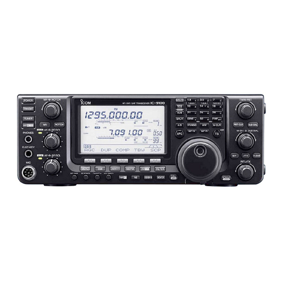
- Page 1 INSTRUCTION MANUAL HF/VHF/UHF TRANSCEIVER i9100...
-
Page 2: Important
SUPPLIED ACCESSORIES Thank you for making the IC-9100 your radio of The transceiver comes with the following accessories. choice. We hope you agree with Icom’s philosophy of Qty. “technology first.” Many hours of research and devel- q Hand microphone ..........1 opment went into the design of your IC-9100. -
Page 3: Precautions
CAUTION: NEVER Icom, Icom Inc. and the Icom logo are registered trademarks of block any cooling vents on Icom Incorporated (Japan) in Japan, the United States, the United the top, rear, sides or bottom of the transceiver. -
Page 4: D-Star Introduction
D-STAR system will automatically route your signal to the desired ham or repeater. Call sign capture allows hams using an Icom radio to “capture” a call sign and automatically program their radio for a reply. Like other communication modes, you can operate simplex D-STAR with other hams, for direct commu- nication. -
Page 5: D D-Star System Description
D D-STAR system description Area 1 Area 2 Area 3 (Gateway) Area 4 Repeater 1 Repeater 2 Repeater 3 Repeater 4 Zone A Internet Internet Area 8 Area 5 Area 6 (Gateway) Area 7 Repeater 5 Repeater 6 Repeater 7 Repeater 8 Zone B Area:... -
Page 6: Table Of Contents
DC POWER SUPPLY ......... 27 D CW sidetone function ........49 ■ Linear amplifier connections ......28 D Connecting the IC-PW1/PW1EURO ... 28 D Connecting a non-Icom linear amplifier ..29 ■ External antenna tuner connection ....29 D Connecting the AH-4 ........29... - Page 7 ■ Electronic keyer functions ....... 50 6 FUNCTIONS FOR TRANSMIT ..... 78–84 D Memory keyer menu construction ....50 ■ VOX function ............ 78 D Memory keyer send menu......51 D Using the VOX function ....... 78 D Editing a memory keyer ......52 D Adjusting the VOX function......
-
Page 8: Table Of Contents
TABLE OF CONTENTS ■ Calling a specific station ........ 103 ■ GPS memory operation ......... 127 D Confirming the setting ....... 105 D Add a GPS memory ........127 D Settings for “UR” and “R2,” depending on the D Edit a GPS memory ........129 D GPS alarm setting ........ - Page 9 12 SATELLITE OPERATION ......153–157 17 MAINTENANCE ........177–182 ■ Satellite communications outline ....153 ■ Troubleshooting ..........177 D Transceiver power ........177 ■ Satellite notes ..........153 D Transmit and receive ......... 177 ■ Selecting the satellite mode ......153 D Transferring the VFO frequencies to the D Scanning ...........
-
Page 10: Panel Description
PANEL DESCRIPTION ■ Front panel !2 !1 q POWER SWITCH [POWER] (p. 31) t HEADPHONE JACK [PHONES] ➥ Push to turn ON the transceiver power. Plug in standard stereo headphones (impedance: 8 • First, confirm the DC power source is turned ON. ø... - Page 11 PANEL DESCRIPTION o MAIN BAND RF GAIN CONTROL/ !0 MAIN BAND AF CONTROL [AF] (inner control; p. 45) SQUELCH CONTROL [RF/SQL] (outer control; p. 44) Rotate to adjust audio output level to the speaker or Rotate to adjust the RF gain and squelch threshold headphones on the MAIN Band.
- Page 12 SSB or AM modes, the ALC • To use this control, first push [NR] (!5 ) . meter swings within the ALC range. Recommended level for Increases Icom microphones Decreases Increases @0 RF POWER CONTROL [RF POWER] (p. 46) Decreases Rotate to continuously vary the RF output power.
- Page 13 PANEL DESCRIPTION @5 VOX/BK-IN SWITCH [VOX/BK-IN] @2 ELECTRONIC CW KEYER SPEED CONTROL VOX SWITCH Operation (p. 78) [KEY SPEED] (p. 49) (Mode: CW) (Mode: SSB/AM/FM/DV) ➥ Push to turn the VOX function ON or OFF. Rotate to adjust the keying speed of the internal ➥...
- Page 14 PANEL DESCRIPTION ■ Front panel (continued) #2 # 3 # 4 # 5 #6 #7 [DV•DR] (p. 85) @9 MODE SWITCHES ➥ Push to select the DV mode. Push to select your desired operating mode. (p. 43) • The built-in speech synthesizer announces the selected •...
- Page 15 • The transmit frequency shifts from the receive fre- band. quency according to the “SPLIT Offset” option in the • Icom’s triple band stacking register memorizes three Set mode. (p. 162) frequencies in each frequency band. • The quick split function can be turned OFF in the “Quick SPLIT”...
- Page 16 PANEL DESCRIPTION ■ Front panel (continued) #8 #9 $ 0 $1 $2 #8 VFO/MEMORY SWITCH [VFO/MEMO] $2 MEMORY CLEAR SWITCH [M-CLR] (p. 141) ➥ Push to switch between the VFO and memory In the Memory mode, hold down for 1 second to modes.
- Page 17 PANEL DESCRIPTION $4 PBT CLEAR SWITCH [PBT-CLR] (p. 75) $7 SUB DIAL CONTROL (Mode: SSB/CW/RTTY/AM) (outer control; p. 33) ➥ Push to display the filter passband width and Rotate to change the SUB Band frequency. shifting value for 1 second on the function dis- Increases play.
- Page 18 PANEL DESCRIPTION ■ Front panel (continued) %1 MAIN DIAL (pp. 37, 161) %4 SPEECH/LOCK SWITCH [SPEECH/LOCK] SPEECH SWITCH Operation (p. 45) Rotate to change the displayed frequency, select ➥ Push to audibly announce the S-meter level, the the Set mode settings, etc. displayed frequency and the operating mode.
-
Page 19: Rear Panel
PANEL DESCRIPTION ■ Rear panel y 430 MHz ANTENNA CONNECTOR [430MHz ANT] q ANTENNA CONNECTOR 1 [ANT1] w ANTENNA CONNECTOR 2 [ANT2] (pp. 24, 25, 158) Connect a 50 ø antenna with a type-N connector (pp. 24, 25, 158) Connect a 50 ø antenna with a PL-259 plug con- for the 430 MHz frequency band. - Page 20 GROUND TERMINAL [GND] (p. 22) !4 ALC INPUT JACK [ALC] (p. 25) Connect this terminal to a ground to prevent electri- Connect to the ALC output jack of a non-Icom linear cal shocks, TVI, BCI and other problems. amplifier.
- Page 21 “USB2/DATA1 Func” (63) item of the Set mode. (p. 167) About the USB driver: The USB driver and the installation guide can be downloaded from our website. ➥ http://www.icom.co.jp/world/index.html The following items are required: • Microsoft ® ®...
-
Page 22: D Acc Socket Information
“1SS133,” on the load side of the circuit to the counter-electromotive force absorption. When the diode is added, a switching delay of the relay may occur. Be sure to check its switching action before operation. [Example] Switching diode To a non-Icom ACC socket linear amplifier eHSEND or uVSEND Relay i13.8 V... -
Page 23: D Data2 Socket Information
PANEL DESCRIPTION • When connecting the ACC conversion cable (OPC-599) Connect to ACC socket ACC 1 ACC 2 o !0 !1 !2 t y u i q w e r q FSKK t AF q 8 V t ALC w GND y SQLS w GND y VSEND... -
Page 24: Lcd Display
PANEL DESCRIPTION ■ LCD display q FREQUENCY READOUTS y MEMORY CHANNEL READOUTS Displays the operating frequency. Displays the selected memory channel. • When the quick tuning icon “Z” is displayed, the fre- u SELECT MEMORY CHANNEL ICON quency changes in pre-set kHz or 1 MHz quick tuning ➥... - Page 25 PANEL DESCRIPTION !3 TONE SQUELCH ICONS !7 EMR MODE ICON (p. 115) (Mode: FM) ➥ Appears when the EMR (Enhanced Monitor Re- ➥ “T” appears when the repeater tone function is ceive) communication mode is selected. • In the EMR communication mode, no call sign set- ON.
- Page 26 PANEL DESCRIPTION ■ LCD display (Continued) @6 @5 @1 SPLIT ICON (p. 82) @7 GPS ICON (p. 132) ➥ Appears when a valid position data is received Appears when the Split function is turned ON. from a GPS receiver that is connected to the @2 DSP FILTER ICON (p.
- Page 27 PANEL DESCRIPTION #3 # 2 #3 #2 $0 SUB DIAL ICON (p. 33) #2 NOISE REDUCTION ICON (p. 77) Appears when the Noise Reduction function is Appears when the SUB Dial function is turned ON. turned ON. ⁄ TUNING DIAL SPEED ICON (p. 39) #3 NOISE BLANKER ICON (p.
-
Page 28: Function Display
PANEL DESCRIPTION ■ Function display Push to select the functions displayed in the display Push [MENU] to toggle the function display menu. • The set of functions assigned to the function switches above switches ([F-1] to [F-5]) • Functions vary, depending on the operating mode. change according to the selected menu and operat- ing mode. -
Page 29: D Function Keys On M1 (Menu 1) Display
PANEL DESCRIPTION Function keys on M1 (Menu 1) display TONE SQUELCH KEY [TON](F-4) (pp. 62–64) (Mode: FM) AGC KEY [AGC](F-1) (p. 72) ➥ Push to select a tone function between subaudible ➥ Push to select the time constant of the AGC circuit. (repeater) tone, tone squelch and DTCS code. -
Page 30: D Function Keys On M3 (Menu 3) Display
PANEL DESCRIPTION ■ Function display (Continued) Function keys on M3 (Menu 3) display Function keys on D2 display (Mode: DV) (Mode: DV) (Only when “ ” is displayed.) CALL SIGN KEY [CS](F-1) (p. 85) SCAN KEY [SCAN](F-1) ➥ Push to start or cancel the Access repeater scan. Push to display the “CS”... -
Page 31: Installation And Connections
INSTALLATION AND CONNECTIONS ■ Selecting a location ■ Grounding Select a location for the transceiver that allows ade- To prevent electrical shock, television interference quate air circulation, free from extreme heat, cold, or (TVI), broadcast interference (BCI) and other prob- vibrations, and away from TV sets, TV antenna ele- lems, ground the transceiver using the GROUND ter- ments, radios and other electromagnetic sources. -
Page 32: Antenna Connection
INSTALLATION AND CONNECTIONS ■ Antenna connection For radio communications, the antenna is of critical Antenna SWR importance, along with output power and receiver sen- Each antenna is tuned for a specified frequency ø sitivity. Select a well-matched 50 antenna and co- range and the SWR usually increases outside the axial cable feedline. -
Page 33: Required Connections
INSTALLATION AND CONNECTIONS ■ Required connections D Rear panel [144MHz ANT] (p. 158) [430MHz ANT] (p. 158) DC POWER SUPPLY (p. 27) PS-126 HF/50MHz ANTENNA 1, 2 (p. 158) Connection example: [ANT1] for 1.8–18 MHz bands antenna [ANT2] for 21–28 MHz bands antenna [1200MHz ANT] (p. -
Page 34: Advanced Connections
AH-4 (option) AH-2b (option) the transceiver and preamplifier. or long wire (p. 29) [ALC], [SEND] (p. 29) Used for connecting a non-Icom linear amplifier. [ANT1], [ANT2] (pp. 28, 29) EXTERNAL SPEAKER Connect a linear amplifier, (MAIN/SUB) antenna selector, etc. SP-23... -
Page 35: External Keypad Connections
INSTALLATION AND CONNECTIONS ■ External keypad connections EXTERNAL KEYPAD 4.7 kø 2.2 kø 1.5 kø 1.5 kø To pin e Connect an external keypad for keyer ± 5% ± 5% ± 5% ± 5% memory control. When using a external keypad, select “KEYER SEND”... -
Page 36: Power Supply Connections
Refer to the diagrams below. • The [POWER] switch is OFF. • Output voltage of the power source is 12 to 15 V when you use a non-Icom power supply. • DC power cable polarity is correct. Red : Positive + terminal Black : Negative _ terminal ■... -
Page 37: Linear Amplifier Connections
INSTALLATION AND CONNECTIONS ■ Linear amplifier connections D Connecting the IC-PW1/PW1EURO Remote control cable (supplied with the IC-PW1/PW1EURO) To an 7-pin side antenna [ACC1] ACC cable (supplied with the IC-PW1/PW1EURO) Coaxial cable [ANT] [REMOTE] ( supplied with the IC-PW1/ [INPUT1] PW1EURO) OPC-599 Coaxial cable*... -
Page 38: D Connecting A Non-Icom Linear Amplifier
INSTALLATION AND CONNECTIONS ■ Linear amplifier connections (Continued) D Connecting a non-Icom linear amplifier To an 50 ø coaxial cable antenna [ANT1] Transceiver RF OUTPUT RF INPUT SEND Non-Icom linear [GND] [ALC] [SEND] amplifier Ground R WARNING! • Set the transceiver output power and linear amplifier ALC output level after referring to the linear amplifier in- struction manual. -
Page 39: Microphone Connector Information
CAUTION: DO NOT short pin 2 to ground as this can damage the internal 8 V regulator. DC voltage is applied to pin 1 for microphone operation. Use caution when using a non-Icom microphone. ■ Microphones D HM-36 q UP/DOWN SWITCHES [UP]/[DN] Push to change the frequency or memory channel. -
Page 40: Basic Operation
BASIC OPERATION ■ Before first applying power After all connections have been made, set controls Before turning ON your transceiver for the first time, and switches as shown in the illustration below. make sure all connections required for your system are complete by reviewing them in Section 2 of this CW : Max. -
Page 41: Main And Sub Bands
BASIC OPERATION ■ MAIN and SUB Bands Both MAIN and SUB Bands have independent features. The IC-9100 can operate on the HF/50 MHz, 144 MHz, MAIN Band : Used for both transmitting and receiving. 430 MHz and 1200 MHz* frequency bands. These fre- The MAIN Band area is in the upper half quency bands can be assigned to the MAIN and SUB of the LCD display. -
Page 42: D Sub Band Setting Mode Operation
BASIC OPERATION D SUB Band setting mode operation Normally, tuning, operating mode selection, memory [SUB] channel selection and programming, are made for the MAIN Band. When the SUB Band setting mode is ON, the settings and selections are for only the SUB Band. •... -
Page 43: Vfo Description
BASIC OPERATION ■ VFO description The IC-9100 has two VFOs; “A” and “B,” for each MAIN and SUB Bands, and are convenient for quickly select- ing two frequencies, or split frequency operation. You can use either VFO to call up a frequency and operat- ing mode. -
Page 44: Selecting A Frequency Band
BASIC OPERATION ■ Selecting a frequency band The frequency band you want to use can be selected in the MAIN and SUB Bands. Before changing the frequency band on the SUB Band, push [SUB] to turn ON the SUB Band setting mode. [BAND](MAIN/SUB) Band keys In addition to the HF/50 MHz, 144 MHz and 430 MHz frequency bands, the IC-9100 can operate on the... - Page 45 BASIC OPERATION (Frequency band: HF/50 MHz) [Example]: 14 MHz frequency band q Hold down [BAND](MAIN/SUB) for 1 second one or more times until a HF/50 MHz frequency band is displayed. w Push a band key ([1.8 1] to [50 0] or [GENE •]). •...
-
Page 46: Frequency Setting
BASIC OPERATION ■ Frequency setting You can select the transceiver’s frequency by using [MAIN DIAL], or you can enter it using the keypad. D Tuning with [MAIN DIAL] q Select the desired frequency band. Band keys • Hold down [BAND](MAIN/SUB) for 1 second one or more times until the desired frequency band is dis- played. -
Page 47: D Quick Tuning Function
BASIC OPERATION D Quick Tuning function [TS] The operating frequency can be changed in ‘kHz’ or ‘MHz’ steps for quick tuning. Select the desired tuning step in each operating fre- quency band and mode. q Push [TS] to select the ‘kHz’ or ‘MHz’ Quick Tuning function step, or turn it OFF. -
Page 48: D Selecting 1 Hz Step
BASIC OPERATION ■ Frequency setting (Continued) D Selecting 1 Hz step [TS] You can change the frequency in 1 Hz steps for fine tuning. q Push [TS] to turn OFF the Quick Tuning function. w Hold down [TS] for 1 second to turn the 1 Hz tuning step ON or OFF. -
Page 49: D About The 5 Mhz Frequency Band Operation (Only Usa Version)
BASIC OPERATION D About the 5 MHz frequency band operation (only USA version) Operation on the 5 MHz band is allowed on 5 discrete IC-9100 Displayed FCC Channel frequencies and must adhere to the following: Frequency* Center Frequency* • The USB mode 5.33050 MHz 5.33200 MHz •... -
Page 50: D Band Edge Warning Beep
BASIC OPERATION ■ Frequency setting (Continued) D Band edge warning beep You can hear a beep tone when you tune into or out of an amateur band’s frequency range. A regular beep sounds when you tune into a range, and an lower tone error beep sounds when you tune out of a range. -
Page 51: D Programming The User Band Edge
BASIC OPERATION [∫] [√] [Ω≈] Keypad D Programming the user band edge When “ON (User)” or “ON (User) & TX” is selected in the “Band Edge Beep” item, the “User Band Edge” item appears in the Set mode. A total of 30 band edge frequencies can be pro- grammed in the “User Band Edge”... -
Page 52: Operating Mode Selection
BASIC OPERATION ■ Operating mode selection • Usable operating modes The usable operating modes in the IC-9100 are listed Mode switch Operating mode to the right. USB Data You can select the desired operating mode by push- [SSB] LSB Data ing the mode switch. -
Page 53: Squelch And Receive (Rf) Sensitivity
BASIC OPERATION ■ Squelch and receive (RF) sensitivity Adjusts the RF gain and squelch threshold level. The [RF/SQL](MAIN Band) squelch removes noise output to the speaker when no signal is received (closed squelch). • The squelch is particularly effective for AM and FM, but can also be used in other modes. -
Page 54: Volume Setting
BASIC OPERATION ■ Volume setting ➥ Rotate the [AF] control clockwise to increase the [AF] audio output level, counterclockwise to decrease it. Increases Decreases [AF] ■ Voice synthesizer operation The IC-9100 has a built-in voice synthesizer to an- nounce the operating frequency, mode and S-meter level in clear, electronically-generated voice, in English (or Japanese). -
Page 55: Basic Transmit Operation
[MIC GAIN] In the AM, FM and DV modes: While speaking into the microphone, rotate [MIC GAIN] with another station listening to your voice for clarity. ALC zone Recommended level for Icom microphones Decreases Increases e Release [PTT] to receive. -
Page 56: Receive And Transmit
RECEIVE AND TRANSMIT ■ Operating SSB q Select the desired frequency band. (p. 35) [TRANSMIT] TX/RX indicator (MAIN Band) w Push [SSB] to select the LSB or USB mode. • When operating above 10 MHz, USB is selected first; when operating below 10 MHz, LSB is selected first. •... -
Page 57: Operating Cw
RECEIVE AND TRANSMIT ■ Operating CW q Select the desired frequency band. (p. 35) [TRANSMIT] TX/RX indicator (MAIN Band) w Push [CW/RTTY] to select CW. • After the CW mode is selected, hold down [CW/RTTY] for 1 second to toggle between CW and CW-R modes, if necessary. -
Page 58: D About The Cw Reverse Mode
RECEIVE AND TRANSMIT ■ Operating CW (Continued) D About the CW reverse mode The CW reverse mode receives signals with a reverse side CW carrier point similar to voice LSB and USB modes. Hold down Use when interfering signals are near a desired signal and you want to reduce the interfering tone. -
Page 59: Electronic Keyer Functions
RECEIVE AND TRANSMIT ■ Electronic keyer functions You can access a number of convenient functions of the built-in electronic keyer in the memory keyer menu. [SEND] [SEND] [EDT] [SET] q In the CW mode, push [MENU] to display the “M1” screen (Menu 1). -
Page 60: D Memory Keyer Send Menu
RECEIVE AND TRANSMIT ■ Electronic keyer functions (Continued) D Memory keyer send menu Pre-set characters can be sent using the Keyer Send menu. Contents of the memory keyer are set in the Edit menu. • Transmitting q In the CW mode, push [MENU] to display the “M1” screen (Menu 1). -
Page 61: D Editing A Memory Keyer
RECEIVE AND TRANSMIT D Editing a memory keyer The contents of the memory keyer memories can be set using the memory keyer edit menu. The memory keyer can memorize and re-transmit 4 CW key codes for often-used CW sentences, contest numbers or a count up trigger. -
Page 62: D Contest Number Set Mode
RECEIVE AND TRANSMIT ■ Electronic keyer functions (Continued) D Contest number Set mode This mode is used to set the contest number, count up trigger and Present number. • Setting contents q In the CW mode, push [MENU] to display the “M1” screen (Menu 1). -
Page 63: D Keyer Set Mode
RECEIVE AND TRANSMIT D Keyer Set mode This Set mode is used to set the CW sidetone, mem- ory keyer repeat time, dash weight, paddle specifica- tions, keyer type, etc. • Setting contents q In the CW mode, push [MENU] to display the “M1” screen (Menu 1). -
Page 64: Paddle Polarity
RECEIVE AND TRANSMIT ■ Electronic keyer functions D Keyer Set mode (continued) Paddle Polarity (Default: NORMAL) Set the paddle polarity. • Normal or reverse polarity can be selected. Keyer Type (Default: ELEC-KEY) Select the keyer type for [ELEC-KEY] connector on the front panel. -
Page 65: Operating Rtty (Fsk)
RECEIVE AND TRANSMIT ■ Operating RTTY (FSK) When using your RTTY terminal or TNC, consult the manual that comes with the equipment. q Select the desired frequency band. (p. 35) [TRANSMIT] w Push [CW/RTTY] once or twice to select the RTTY mode. -
Page 66: Rtty Functions
RECEIVE AND TRANSMIT ■ RTTY functions The RTTY menu has a number of convenient functions for RTTY operation. q Push [CW/RTTY] once or twice to select the RTTY mode. [RTTY]/[TPF] [SET] [DEC] • After the RTTY mode is selected, hold down [CW/RTTY] normal and reverse for 1 second to toggle between modes, if needed. -
Page 67: D About Rtty Reverse Mode
RECEIVE AND TRANSMIT D About RTTY reverse mode Received characters are occasionally garbled when the Mark and Space signals are reversed. This rever- sal can be caused by incorrect TNC connections, set- ting or commands. To receive reversed RTTY signals correctly, select the RTTY reverse mode. -
Page 68: D Rtty Decoder
RECEIVE AND TRANSMIT ■ RTTY functions (Continued) D RTTY decoder The transceiver has an RTTY decoder for Baudot (mark freq.: 2125 Hz, shift freq.: 170 Hz, 45 bps). An external terminal unit (TU) or terminal node con- nector (TNC) is not necessary for receiving a Baudot signal. -
Page 69: D Rtty Set Mode
RECEIVE AND TRANSMIT D RTTY Set mode The RTTY Set mode is used to set the mark and shift frequencies, keying type, decode USOS function, RTTY decoder new line code and the number of de- code screen display lines. • Setting contents q In the RTTY mode, push [MENU] to display the “M1”... -
Page 70: Operating Am/Fm
RECEIVE AND TRANSMIT ■ Operating AM/FM q Select the desired frequency band. (p. 35) [TRANSMIT] TX/RX indicator (MAIN Band) w Push [AM/FM] to select the AM or FM mode. • After AM or FM is selected, hold down [AM/FM] for 1 second to select the data mode, if needed. -
Page 71: Tone Squelch Operation
RECEIVE AND TRANSMIT ■ Tone squelch operation The tone squelch opens only when you receive a sig- [F-3] nal containing a matching subaudible tone. You can silently wait for calls from others using the same tone. q Push [AM/FM] once or twice to select the FM mode. -
Page 72: Dtcs Operation
RECEIVE AND TRANSMIT ■ DTCS operation The DTCS function is another method of communica- [F-3] [TON](F-4) tions using selective calling. Only received signals hav- ing a matching 3-digit code will open the squelch. q Push [AM/FM] once or twice to select the FM mode. -
Page 73: Tone Scan/Dtcs Code Scan Operation
RECEIVE AND TRANSMIT ■ Tone scan/DTCS code scan operation To search for a repeater’s sub-audible tone frequency, [TON] [SCAN] a tone scan is available. By monitoring a repeater signal with a tone squelch or DTCS, you can determine the tone frequency neces- sary to open the repeater or the squelch. -
Page 74: Repeater Operation
RECEIVE AND TRANSMIT ■ Repeater operation A repeater receives transmitted signals and re-trans- mits them on a different frequency. When using a re- peater, the transmit frequency is shifted from the re- ceive frequency by a frequency offset. A repeater can be accessed using the duplex opera- tion to set the frequency shift to the same value as the repeater’s frequency offset. -
Page 75: D One-Touch Repeater Function
RECEIVE AND TRANSMIT D One-touch repeater function This function allows you to set the repeater operation by holding down one switch. First, set the frequency offset as well as the repeater access tone frequency (p. 163). q Select the desired frequency band. (p. 35) w In the FM mode, push [A/B] to select VFO A. -
Page 76: D Setting The Auto Repeater Ranges (U.s.a. And Korea Versions Only)
RECEIVE AND TRANSMIT Repeater operation (Continued) D Setting the Auto Repeater ranges (U.S.A. and Korea versions only) [POWER] [AM/FM] [BAND](MAIN/SUB) [F-INP ENT] The transceiver has three Auto Repeater ranges that can be used for each frequency band. And you can set the desired Auto Repeater ranges by programming the lower and higher edge frequencies into the allowable Memory channel of each band as described below. -
Page 77: D Turning On The Auto Repeater Function (U.s.a. And Korea Versions Only)
RECEIVE AND TRANSMIT D Turning ON the Auto Repeater function (U.S.A. and Korea versions only) When the operating frequency falls within the repeater [∫] [√] output frequency range, the Auto Repeater function automatically sets the repeater settings (duplex ON/ OFF, duplex direction, tone encoder ON/OFF). q Hold down [MENU] for 1 second to enter the Set mode. -
Page 78: Functions For Receive
FUNCTIONS FOR RECEIVE ■ AFC operation [AFC] (Mode: FM/DV) AFC stands for Automatic Frequency Control. The AFC function tunes the displayed frequency automatically when an off-center frequency is received. q Push [AM/FM] or [DV•DR] once or twice to select the FM or DV mode. w Push [MENU] to display the “M1”... -
Page 79: Simple Band Scope
FUNCTIONS FOR RECEIVE ■ Simple band scope Blinks when the reference frequency is outside of the sweep range. The Band Scope function allows you to visually check the location and strength of signals around a specified S T E P frequency. -
Page 80: Preamplifier
FUNCTIONS FOR RECEIVE ■ Preamplifier The preamplifier amplifies weak signals in the receiver front end, to improve the S/N ratio and sensitivity. Turn this function ON when receiving weak signals. The AG-25, AG-35 or AG-1200* preamplifier unit is required for 144, 430 or 1200 MHz* frequency band. -
Page 81: Agc Function
FUNCTIONS FOR RECEIVE ■ AGC function The AGC (Auto Gain Control) controls receiver gain to produce a constant audio output level, even when the received signal strength varies greatly. The transceiver has 3 pre-set AGC time constants: fast, mid and slow for SSB, CW, RTTY and AM modes. In the FM and DV modes, the AGC time constant is fixed as “FAST”... -
Page 82: If Filter Selection
FUNCTIONS FOR RECEIVE ■ IF filter selection The transceiver has 3 passband width IF filters for each mode. The filter selection is automatically memorized in each mode. The PBT shift frequencies are automatically memo- rized in each filter. [FILTER] D IF filter selection Filter selection q Select the desired mode. -
Page 83: D 1St If Filter Selection
FUNCTIONS FOR RECEIVE D 1st IF filter selection (Mode: SSB/CW/RTTY/AM) The IC-9100 has a 15 kHz filter passband width at the [F-3] [F-5] 1st IF frequency. The 1st IF filters reduce interference from strong nearby signals. st if filter (6 k If the optional FL-430 is installed, a 6 kHz filter width can be used. -
Page 84: Twin Pbt Operation
FUNCTIONS FOR RECEIVE ■ Twin PBT operation (Mode: SSB/CW/RTTY/AM) [PBT-CLR] [TWIN-PBT] To reject interference, PBT (Passband Tuning) elec- tronically narrows the IF passband width by shifting the IF frequency slightly outside of the IF filter passband. The IC-9100 uses DSP for the PBT function. Moving both [TWIN-PBT] controls shift the IF passband cen- ter frequency both above and below the received fre- quency. -
Page 85: Noise Blanker
FUNCTIONS FOR RECEIVE ■ Noise Blanker (Mode: SSB/CW/RTTY/AM) The Noise Blanker eliminates pulse-type noise such as noise from car ignitions. ➥ Push [NB] to turn the Noise Blanker function ON or OFF. • “NB” is displayed when the Noise Blanker is ON. [NB] Appears When using the Noise Blanker function, received... -
Page 86: Noise Reduction
FUNCTIONS FOR RECEIVE ■ Noise Reduction [NR] [NR] control The Noise Reduction function reduces random noise components and enhances audio signals which are buried in noise. The received signals are converted to digital signals and then the audio signals are sepa- rated from the noise. -
Page 87: Functions For Transmit
FUNCTIONS FOR TRANSMIT ■ VOX function (Mode: SSB/AM/FM/DV) The VOX (Voice-Operated Transmission) function switches the transceiver between transmit and receive with your voice. This function provides hands-free op- eration. D Using the VOX function [VOX/BK-IN] q Select a phone mode (SSB, AM, FM, DV). (p. 43) Appears w Push [VOX/BK-IN] to turn ON the VOX function. -
Page 88: Break-In Function
FUNCTIONS FOR TRANSMIT ■ Break-in function (Mode: CW) [MENU] [CW/RTTY] The Break-in function is used in the CW mode to auto- matically toggle the transceiver between transmit and receive when keying. The IC-9100 is capable of Full Break-in or Semi Break-in. [KEY SPEED] [VOX/BK-IN] [MAIN DIAL]... -
Page 89: Speech Compressor
FUNCTIONS FOR TRANSMIT ■ Speech compressor (Mode: SSB) [MENU] [COMP] The Speech Compressor function increases average RF output power, improving signal strength and read- ability. q Push [SSB] to select the USB or LSB mode. w Adjust the [MIC GAIN] control so that the ALC meter reads within the ALC zone, whether or not you speak softly or loudly. -
Page 90: Tx Function
FUNCTIONS FOR TRANSMIT ■ ∂TX function The ∂TX function shifts the transmit frequency up to [CLEAR] ±9.99 kHz in 10 Hz steps* without changing the re- ceive frequency. * The [RIT/∂TX] control tunes in 1 Hz steps when the operating frequency readout is set to the 1 Hz step readout. -
Page 91: Split Frequency Operation
FUNCTIONS FOR TRANSMIT ■ Split frequency operation Split frequency operation allows you to transmit and [A/B] [SPLIT] receive on two different frequencies. Split frequency operation is performed using frequencies in VFO A and VFO B. • The Split frequency operation is automatically turned OFF when turning ON the One-touch repeater function. -
Page 92: Quick Split Function
FUNCTIONS FOR TRANSMIT ■ Quick Split function [SPLIT] When you hold down [SPLIT] for 1 second, the Split frequency operation is turned ON. The undisplayed VFO is automatically changed according to the plus/ minus frequency shift programmed in the Set mode. Or the VFOs are equalized when 0 kHz (default setting) is programmed as the split frequency shift. -
Page 93: Measuring Swr
FUNCTIONS FOR TRANSMIT ■ Measuring SWR (Band: HF/50/144/430 MHz) The antenna SWR cannot be measured on the 1200 The IC-9100 has a built-in circuit for measuring an- MHz frequency band*. tenna SWR— no external equipment or special adjust- * The optional UX-9100 is required. ments are necessary. -
Page 94: Dv Mode Programming
DV MODE PROGRAMMING The optional UT-121 is required for DV mode opera- tion. ■ Call sign programming [CS]/[√] [EDT] Four types of call signs are used; “MY” (your own call sign) “UR” (destination call sign, whether it is an indi- vidual or a repeater.) “R1”... -
Page 95: D "Ur" (Destination Call Sign) Programming
DV MODE PROGRAMMING “UR” (Destination call sign) programming [CS]/[√] [EDT] A destination call sign must be programmed to a spe- cific individual station or a repeater, for both digital voice and low-speed data communications. q Push [DV•DR] to select the DV mode. w Push [MENU] one or more times to display the “M3”... -
Page 96: R2" (Link/Gateway Repeater Call Sign) Programming
DV MODE PROGRAMMING ■ Call sign programming (Continued) Access/Area repeater call sign Link/Gateway repeater call sign “R1” ( ) and “R2” ( ) programming The access/area and link/gateway repeater call signs [CS]/[√] [EDT] must be programmed in “R1” and “R2.” Other repeater call signs can be stored in the “RP-L”... -
Page 97: Repeater List
DV MODE PROGRAMMING ■ Repeater list You can store repeater information for quick and simple NOTE: Repeater lists can be erased by static elec- communication in up to 500 repeater memory chan- tricity, electric transients, etc. In addition, they can nels (Repeater list) in up to 10 Groups. -
Page 98: Repeater List Programming
DV MODE PROGRAMMING ■ Repeater list programming New repeater list programming i Rotate [MAIN DIAL] to select the first character or symbol to input. q Push [DV•DR] to select the DV mode. When inputting numbers or a decimal point, push w Push [MENU] one or more times to display the “M3”... - Page 99 DV MODE PROGRAMMING Gateway r epeater call sign programming Access repeater setting (R1 USE) When the repeater that was programmed in the pre- The programmed repeaters can be set as an access vious item has its own gateway capability, skip this repeater (R1) in the DR mode.
-
Page 100: Editing A Repeater List
DV MODE PROGRAMMING ■ Editing a repeater list ■ Repeater list programming (Continued) Duplex direction setting (DUP) This function re-programs a repeater’s data. This is This content appears when “YES” is selected in “R1 useful when already-programmed data is incorrect or USE”... -
Page 101: Clearing A Repeater List
DV MODE PROGRAMMING ■ Clearing a repeater list After programming Contents of programmed list can be cleared (erased). To add the programmed data as a new list: q Push [DV•DR] to select the DV mode. !0 Push [Z](F-2) to select the “ADD Write” item, then w Push [MENU] one or more times to display the “M3”... -
Page 102: Dv Mode Operation
DV MODE OPERATION ■ Digital mode operation The IC-9100 can be operated in the digital voice mode, About the Time-Out Timer function including low-speed data operation, for both transmit The IC-9100 has a Time-Out Timer function for digi- and receive. It can also be connected to a GPS re- tal repeater operation. -
Page 103: Receiving A D-Star Repeater
DV MODE OPERATION ■ Receiving a D-STAR repeater [A/B] [VFO/MEMO] When the IC-9100 receives a signal from a D-STAR repeater, it receives four call signs: the calling station’s call sign, the called station’s call sign, the R1 repeater call sign (the repeater that receives a signal from the calling station on the uplink frequency), and the R2 re- peater call sign (the repeater that transmits a signal on the downlink frequency). -
Page 104: Received Call Signs
DV MODE OPERATION ■ Received call signs When a call is received in the DV mode, the calling sta- [√] [CD] [CLR] tion and repeater call signs being used can be stored in the received call record. The stored call signs can be displayed in the following manner. -
Page 105: D One-Touch Reply Using The Call Record
DV MODE OPERATION D One-touch reply using the call record [TRANSMIT] [R>CS] The calling station’s call sign, which is stored in the call record, can be used to quickly and easily reply. • First, set your own call sign (MY). (p. 85) •... -
Page 106: Copying The Call Sign
DV MODE OPERATION ■ Copying the call sign D Copying the call sign memory contents [√] [CD] [CLR] The memorized UR call sign can be copied into an- other call sign memory. NOTE: First, make sure that the “Edit Record” item is set to “Auto”... -
Page 107: D Copying The Call Record Contents Into Call Sign Memory
DV MODE OPERATION D Copying the call record contents into call sign memory When “CALLER” is selected in step y: This is a way to copy the call record data (“CALLER,” “RXRPT1” and “RXRPT2”) into call sign memory “UR” u Select the desired copy destination and a repeater all at the same time, or individually. -
Page 108: Dr (D-Star Repeater) Mode Operation
DV MODE OPERATION ■ DR (D-STAR Repeater) mode operation DR (D-STAR Repeater) mode is used for D-STAR repeater operation. In this mode, you can select the pre-programmed repeaters and UR call sign by using [MAIN DIAL]. • DR mode operation flow chart Step 1: (R1 selection) : H I R A N O 4 3 GRP3... -
Page 109: D Access Repeater Scan
DV MODE OPERATION D Access repeater scan [SCAN] The Access repeater scan is useful to find a repeater. For rapidly find, the Access repeater scan skips the repeaters which are not specified as a scan target. You can select the desired repeaters as a scan target. See page 90 or ‘Access repeater scan’s target setting’... -
Page 110: Calling Cq
DV MODE OPERATION ■ Calling CQ First, program a MY call sign in step q. Next program the repeater list (p. 89). After that, follow this guide to access a D-STAR repeater. The optional CS-9100* cloning software is helpful for programming call signs and programming the repeater list. -
Page 111: D Storing The Set Data
DV MODE OPERATION Making a Zone CQ/Gateway CQ call NOTE: The settings are the same between Zone CQ and Gateway CQ call. • Calling CQ through a link repeater in the same zone (Zone CQ) Area Zone Repeater q NARA43 (JP3YHL) My call sign JA3YUA Repeater r IKOMA43 (JP3YHJ) -
Page 112: Calling A Specific Station
DV MODE OPERATION ■ Calling a specific station This section describes how to call a specific station using the DR mode. When the Link repeater (R2) is set to “GW,” the des- ignated gateway repeater is automatically set as the Link repeater, and you can make a call to a specific station through the internet. - Page 113 DV MODE OPERATION Making a call to an individual station through a link repeater in the same zone (Zone call) [TRANSMIT] [UR] [MW] Zone Area Repeater q NARA43 (JP3YHL) MY call sign Station call sign JA3YUA JG3YMK Repeater r IKOMA-43 (JP3YHJ) u Rotate [MAIN DIAL] to select the link repeater in the same zone.
-
Page 114: D Confirming The Setting
DV MODE OPERATION ■ Calling a specific station (Continued) D Confirming the setting q In the DR mode, push [MENU] one or more times to display the “D1” screen. w Push [CS](F-1) to display the “CS” screen (Call Sign). e Push [Z](F-1) one or more times to sequentially display the “UR,”... -
Page 115: Simplex Operation Using The Vfo
DV MODE OPERATION ■ Simplex operation using the VFO D Making a simplex CQ call or a call to an individual station • Calling CQ • Calling an individual station MY call sign JA3YUA Station call sign My call sign JG3YMK JA3YUA ≈CQCQCQ... -
Page 116: Repeater Operation Using The Vfo
DV MODE OPERATION ■ Repeater operation using the VFO D Making a CQ call or a call to an individual station through your local area (access) re- peater (Local Area call) • Calling CQ • Calling an individual station Zone Zone Area Area... -
Page 117: D Making A Cq Call Or A Call To An Individual Station Through A Link Repeater In The Same Zone (Zone Call)
DV MODE OPERATION D Making a CQ call or a call to an individual station through a link repeater in the same zone (Zone call) • Calling CQ • Calling an individual station Area Area Zone Zone Repeater q JP3YHL Repeater q JP3YHL My call sign Station call sign... -
Page 118: D Making A Cq Call Or A Call To An Individual Station Through Gateway Repeaters (Gateway Call)
DV MODE OPERATION ■ Repeater operation in the VFO (Continued) D Making a CQ call or a call to an individual station through gateway repeaters (Gateway call) • Calling CQ • Calling an individual station Zone A Zone A Gateway Area Gateway Area... -
Page 119: D Settings For "Ur" And "R2," Depending On The Communication Form
DV MODE OPERATION D Settings for “UR” and “R2,” depending on the communication form Destination: CQ Destination: An individual station <Communication form: Local area call> <Communication form: Local area call> • UR setting: CQCQCQ • UR setting: An individual station •... -
Page 120: Message Operation
DV MODE OPERATION ■ Message operation [EDT] [DSET] D TX message programming The transceiver has a total of 5 message memories to store short messages to transmit during DV mode operation. Message of up to 20 characters can be pro- grammed for each memory. -
Page 121: D Message Transmission
DV MODE OPERATION D Message Transmission You can select a message channel (TM1–TM5) to turn ON the message transmission function. When a mes- sage channel is selected, the transceiver transmits the pre-programmed text message. The default setting is [TRANSMIT] [DSET]/[SET] OFF. -
Page 122: Dv Automatic Detection
DV MODE OPERATION ■ DV automatic detection [�] [�] [DSET]/[SET] When a non-digital signal is received during DV mode operation, the “DV” and “FM” icons simultaneously blink. The transceiver automatically selects the FM mode to monitor the signal, if the DV Auto Detect func- tion is turned ON. -
Page 123: Digital Squelch Functions
DV MODE OPERATION ■ Digital squelch functions The digital squelch opens only when receiving a sig- nal addressed to your own call sign, or a signal that includes a matching digital code. You can silently wait for calls from others. [DSQ] NOTE: Use digital code squelch function when com- municating with two or more stations, because the... -
Page 124: Emr Communication
DV MODE OPERATION ■ EMR communication [TRANSMIT] [�] [�] [DSET]/[SET] The EMR (Enhanced Monitor Receive) communication mode can be used in only the DV mode. In the EMR mode, no call sign setting is necessary. When an EMR mode signal is received, the audio (voice) will be heard at the specified level, even if the volume setting level is set to the minimum level, or digital call sign/digital code squelch is in use. -
Page 125: Bk Mode Communication
DV MODE OPERATION ■ BK mode communication The BK (Break-in) function allows you to break into a conversation, where the two other stations are com- municating with call sign squelch enabled. [TRANSMIT] [�] [�] [DSET]/[SET] q While receiving another station’s communication in the DV mode, push [MENU] one or more times to display the “M3”... -
Page 126: Low-Speed Data Communication
DV MODE OPERATION ■ Low-speed data communication D Low-speed data communication In addition to digital voice communication, low-speed application setting data communication can be made. data communication Use the optional OPC-1529R Configure the serial data communication software as cable with a third-party serial data communication follows. -
Page 127: Dv Set Mode Description
DV MODE OPERATION ■ DV Set mode description [�] [�] [DSET]/[SET] The DV Set mode is used for programming infrequently changed values or functions in the DV mode. D DV Set mode settings q In the DV mode, push [MENU] one or more times to display the “M3”... - Page 128 DV MODE OPERATION ■ DV Set mode description (Continued) RX RPT Write RX Record (RPT) (Default: OFF) (Default: ALL) Turn the repeater call sign automatic write function ON The transceiver can record data of up to 20 individual or OFF. calls.
- Page 129 DV MODE OPERATION Opening Call Sign (Default: OFF) Select whether or not to display MY call sign on the LCD when the transceiver is turned ON. • OFF : Turns OFF the function. • ON : Displays MY call sign at power ON. (Default: OFF) The break-in function allows you to break into a con- versation where two other stations are communicating...
-
Page 130: Gps/Gps-A Operation
GPS/GPS-A OPERATION ■ GPS operation • To connect the GPS receiver You can display your own GPS data in all operating modes. You can also transmit GPS data when in the DV mode. To receive GPS data, connect a third-party GPS receiver that has an RS-232C output and NMEA data format. -
Page 131: D Gps Data Communication
GPS/GPS-A OPERATION D GPS data communication [∫] [√] The transceiver transmits GPS data or low-speed data to the PC through the [DATA1] jack, depending on the Set mode setting. (p. 168) q Hold down [MENU] for 1 second to enter the Set mode. -
Page 132: D Position Display
GPS/GPS-A OPERATION ■ GPS operation (Continued) D Position display q Hold down [CALL/GPS] for 1 second to display the [POS] “GPS” screen. w Push [POS](F-1) to display the position data. Then push [F-2] one or more times to display your current position, received position or GPS memory alarm position information. -
Page 133: D Saving Your Own Or Received Position Data
GPS/GPS-A OPERATION D Saving your own or received position data [F-2] [F-5] q Hold down [CALL/GPS] for 1 second to display the “GPS” screen. w Push [POS](F-1), then push [F-2] once or twice to display your own or the caller’s (other station) posi- tion information. -
Page 134: D Gps Message Programming
GPS/GPS-A OPERATION ■ GPS operation (Continued) D GPS message programming [TXM] [MSG] Enter a GPS message of up to 20 characters to be transmitted with the position data. q Hold down [CALL/GPS] for 1 second to display the “GPS” screen. w Push [MSG](F-3) to display the “MSG”... -
Page 135: D Received Gps Message Display
GPS/GPS-A OPERATION D Received GPS message display [RXM] [MSG] q Hold down [CALL/GPS] for 1 second to display the “GPS” screen. w Push [MSG](F-3) to display the “MSG” screen (GPS Message). e Push [RXM](F-2) to display the “RXM” screen (RX message). -
Page 136: Gps Memory Operation
GPS/GPS-A OPERATION ■ GPS memory operation [GPM]/[√] The transceiver has 50 GPS memory channels to store the received position data, or other-used position data, along with an alphanumeric channel name. D Add a GPS memory q Hold down [CALL/GPS] for 1 second to display the “GPS”... - Page 137 GPS/GPS-A OPERATION • To program a latitude or longitude Latitude data programming u When “LAT” is selected, rotate [MAIN DIAL] to enter the desired latitude data. North latitude • A cursor blinks on the programmable digit. Blinks is selected. • Push [Ω ≈](F-3) to select the digit. •...
-
Page 138: D Edit A Gps Memory
GPS/GPS-A OPERATION ■ GPS memory operation (Continued) D Edit a GPS memory [GPM]/[EDT]/[√] The GPS memory name, latitude and longitude data, time data and a memory bank name can be edited. q Hold down [CALL/GPS] for 1 second to display the “GPS”... -
Page 139: D Gps Alarm Setting
GPS/GPS-A OPERATION D GPS alarm setting [GPM] [ALM] A GPS alarm can sound when a target position comes into the alarm area. This function can be set to the caller station, all GPS Memory channels, a specified Memory bank or a specified Memory channel. q Hold down [CALL/GPS] for 1 second to display the “GPS”... -
Page 140: D Gps Memory Clearing
GPS/GPS-A OPERATION ■ GPS memory operation (Continued) [GPM] [YES] [NO] D GPS memory clearing • Clear all memory channels q Hold down [CALL/GPS] for 1 second to display the “GPS” screen. w Push [GPM](F-2) to display the “GPM” screen (GPS Memory). -
Page 141: Gps Set Mode
GPS/GPS-A OPERATION ■ GPS Set mode [∫] [√] [√] [SET] The following individual settings are selectable in the GPS Set mode. Set them to suit your GPS operating needs. q Hold down [CALL/GPS] for 1 second to display the “GPS” screen. w Push [SET](F-5) to enter the GPS Set mode. - Page 142 GPS/GPS-A OPERATION ■ GPS Set mode (Continued) Alarm Area1 Alarm Area2 (Default: 0.25') (Default: Both) When the GPS Alarm function is set to “ALL” or one of When the GPS Alarm function is set to the memory the memory banks, set the GPS alarm active range. channel or “RX,”...
-
Page 143: Unproto Address
GPS/GPS-A OPERATION GPS Sentence (GSV) (Default: OFF) (Default: OFF) GPS Auto TX Select the desired interval from OFF, 5, 10, 30 sec- Turn the GPS sentence formatter “GSV” ON or OFF. onds, 1, 3, 5, 10 or 30 minutes for automatic position NOTE for GPS sentences: data transmission. - Page 144 GPS/GPS-A OPERATION ■ GPS Set mode (Continued) Data Extension t Push [F-1] one or more times to select the desired (Default: OFF) character type. Set the data extension capability to “Course/Speed” Character or OFF. Selectable characters type When you select “Course/Speed,” the transceiver’s course and speed information is transmitted along with A to Z the position data.
- Page 145 GPS/GPS-A OPERATION Comment Program a comment of up to 43 characters. The programmed comment is transmitted with the GPS position data. See ‘Comment programming,’ as described below. This item appears when “Data Extension” is set to OFF, as described on page 135. Comment (Extension) Program a comment of up to 36 characters.
-
Page 146: Gps-A Operation
GPS/GPS-A OPERATION ■ GPS-A operation D GPS-A code details D GPS-A function In GPS-A operation, the following codes are transmit- Set the following to activate the GPS-A function. q Push [DV•DR] to select the DV mode. ted to the PC connected to the IC-9100. ®... -
Page 147: Memory Operation
MEMORY OPERATION ■ General description The transceiver has 106 Memory channels in each fre- NOTE: quency band. (99 regular, 6 scan edges and 1 call) Memory data can be erased by static electricity, elec- The Memory mode is very useful to quickly change to tric transients, etc. -
Page 148: Memory Channel Selection
MEMORY OPERATION ■ Memory channel selection When the SUB Band setting is turned ON, you can se- [VFO/MEMO] lect a Memory channel in the SUB Band as well as in the MAIN Band. (p. 33) • “ ” appears when the SUB Band setting is ON. D Selection in the VFO mode q Push [VFO/MEMO] to select the VFO mode. -
Page 149: Memory Channel Programming
MEMORY OPERATION ■ Memory channel programming Memory channels can be programmed in either the [VFO/MEMO] [MW] VFO mode or the Memory mode. D Programming in the VFO mode q Push [VFO/MEMO] to select the VFO mode. w Set the desired settings into both VFO A and VFO ➥... -
Page 150: Call Channel Programming
MEMORY OPERATION ■ Call channel programming The Call channel is programmed in the same way as [MW] the regular Memory channels are. It is convenient to program a most-often-used frequency into the Call channel for quick recall. As with Memory channels, the Call channel can also hold split frequencies, and other parameters. -
Page 151: Memory Contents Copying
MEMORY OPERATION ■ Memory contents copying [VFO/MEMO] The Memory channel contents (frequency, operating mode, etc.) can be copied to the VFO. The copy can be performed in either the VFO mode or the Memory mode. D Copying in the VFO mode This is useful for copying programmed contents to a displayed VFO. -
Page 152: Memory Name Programming
MEMORY OPERATION ■ Memory name programming [EDT] [MEM] [VFO/MEMO] All Memory channels, including scan edges and Call channel, can be tagged with alphanumeric names of up to 9 characters each. [EXAMPLE]: Programming a memory name into Memory channel 99. q Push [VFO/MEMO] to select the Memory mode. [MENU] [M-CH] w Rotate [M-CH] to select Memory channel 99. -
Page 153: Memo Pad Function
MEMORY OPERATION ■ Memo pad function Memo pads are convenient when you want to memo- The transceiver has a Memo pad function to store rize the displayed data temporarily, such as when you the displayed data for easy writing and recalling. The find a DX station in a pile-up, or when a desired station memo pads are separate from the Memory channels. -
Page 154: Scans
SCANS ■ Scan types The MAIN and SUB Bands can be independently Scanning automatically searches for signals and scanned. When the SUB Band setting mode is turned ON makes it easier to locate new stations for contact or lis- tening purposes. The IC-9100 has several scan types; (“... -
Page 155: Preparation
SCANS ■ Preparation • [MAIN DIAL] function For a Programmed scan: How the [MAIN DIAL] functions during a scan, can be Program scan edge frequencies into Program Scan set in the Scan Set mode. (p. 147) Edge channels “1A–3A” and “1b–3b.” (p. 148) For a Memory scan: •... -
Page 156: Scan Set Mode
SCANS ■ Scan set mode [SCAN]/[∫] [√] [SET] The scan speed, Scan Resume function and [MAIN DIAL] scan function can be set in the Scan Set mode. q Push [MENU] one or more times to display the “M2” screen (Menu 2). w Push [SCAN](F-1) to display the “SCAN”... -
Page 157: Scan Edges Programming
SCANS ■ Scan edges programming Memory channels 1A–3A and 1b–3b are the Program Scan Edge channels. They are used to program the upper and lower frequency edges for programmed scans. (p. 149) Each frequency band has its own Scan Edge chan- nels. -
Page 158: Programmed Scan/Fine Programmed Scan (Vfo Mode)
SCANS ■ Programmed scan/Fine programmed scan (VFO mode) A programmed scan searches for signals between [SCAN]/[PRO] [VFO/MEMO] [TS] Program Scan Edge channels “1A–3A” and “1b–3b.” Before starting the programmed scan, scan edges must be programmed into these channels. See the previous page for scan edge programming. If the same frequencies are programmed into the Program Scan Edge channels, the programmed scan will not start. -
Page 159: Memory Scan (Memory Mode)
SCANS ■ Memory scan (Memory mode) D Memory scan A Memory scan searches for signals through Memory [SCAN]/[MEM] [VFO/MEMO] channels 1 to 99. Blank (unprogrammed) Memory channels are skipped. NOTE: For a Memory scan to start, two or more Memory channels must be programmed. (p. 140) q Push [VFO/MEMO] to select the memory mode. -
Page 160: D Setting/Cancelling Select Memory Channels
SCANS ■ Memory scan (Memory mode) (Continued) D Setting/Cancelling Select Memory channels Appears All Memory channels can be set as Select Memory channels, except for the Scan Edge and Call channels. ➥ When the “SCAN” screen is displayed, push [SEL] (F-3), or when the “MEM”... -
Page 161: F Scan And Fine ∂F Scan
SCANS ■ ∂F scan and Fine ∂F scan [SCAN] [VFO/MEMO] Keypad [M-CH] ∂F (Delta Frequency) scan searches for signals within the specified range with the displayed VFO frequency or Memory channel frequency as the center frequency. The frequency range is specified by the width of the selected span. -
Page 162: Satellite Operation
SATELLITE OPERATION ■ Satellite communications outline Both Satellite Mode B (435 MHz uplink, 145 MHz Orbit information downlink) and Mode J (145 MHz uplink, 435 MHz Orbit information describes satellite location, reach- downlink) can be operated with the IC-9100, and ing angles, etc. -
Page 163: Setting The Satellite Vfo
SATELLITE OPERATION ■ Setting the satellite VFO [MAIN] [SUB] [VFO/MEMO] [SUB] [SATELLITE] (1.8 1) (3.5 2) q Push [SATELLITE] to enter the satellite mode. • “ ” and either “ ” or “ ” appear. w Push [VFO/MEMO] to toggle between the satellite VFO and Memory mode. -
Page 164: Satellite Memory
SATELLITE OPERATION ■ Satellite memory The IC-9100 has 20 satellite memory channels (CH 00 to 19) to memorize both uplink and downlink frequen- cies, operating modes and other data. Downlink (Receive) frequency D Satellite memory selection q Push [SATELLITE] to enter the satellite mode. w Push [VFO/MEMO] to select the satellite memory mode. -
Page 165: Preparation
SATELLITE OPERATION ■ Preparation Downlink (receive) frequency q Decide on a usable satellite, and point your antenna direction towards it. w Confirm the approximate location of the satellite and operating mode (e.g. “B,” “J,” etc.) through a publication (magazine, etc.) or an appropriate sat- ellite tracking software. -
Page 166: Satellite Operation
SATELLITE OPERATION ■ Satellite operation When your own signal can be received with a loop test, satellite communication can be performed. q When a frequency is shifted by the Doppler effect, push [SUB](3.5 2), then rotate [MAIN DIAL] to re- tune the uplink frequency. -
Page 167: Antenna Tuner Operation
ANTENNA TUNER OPERATION ■ Antenna connection and selection The IC-9100 has 2 antenna connectors for the HF/50 [ANT•METER] MHz bands, [ANT1] and [ANT2], and a dedicated an- tenna connector for each of the 144 MHz, 430 MHz and 1200 MHz* bands; a total of 5 antenna connec- tors. -
Page 168: Antenna Tuner Operation
ANTENNA TUNER OPERATION ■ Antenna tuner operation The internal automatic antenna tuner automatically NOTES: matches the transceiver to the selected antenna. After • The internal antenna tuner can only tune the HF the tuner matches an antenna, the variable capacitor set- and 50 MHz bands—... -
Page 169: Optional External Tuner Operation
ANTENNA TUNER OPERATION • Automatic tuner start (HF bands only) • PTT tuner start If you want to deactivate the tuner when the VSWR Tuning of the internal*/external antenna tuner starts is 1.5:1 or less, use the auto tuner start function and when [PTT] is pushed on a new frequency that is more than 1% away from the last-tuned frequency. -
Page 170: Set Mode
SET MODE ■ Set mode description [∫] [√] [√] The Set mode is used for programming infrequently changed values or functions. D The Set mode settings q Hold down [MENU] for 1 second to enter the Set mode. w Push [Y](F-1) or [Z](F-2) to select the desired [MENU] [F-3] [MAIN DIAL]... -
Page 171: Meter Peak Hold
SET MODE User Band Edge Time Out Timer (Default: OFF) This “User Band Edge” item appears only when “ON To prevent a prolonged transmission, the transceiver (User)” or “User (ON) & TX” is selected in the “Band has a Time-Out Timer function. Edge Beep”... -
Page 172: Auto Repeater
SET MODE ■ Set mode description (Continued) DUP Offset Tuner (Auto Start) (Default: OFF) Set the offset* for duplex operation. You can set the Turn the Automatic Antenna Tuner function ON or repeater offset for each band. OFF. This function is for only the HF bands. *The difference between transmit and receive frequencies. -
Page 173: Memopad Numbers
SET MODE SPEECH Level (Default: 50%) (Default: HIGH) MAIN DIAL Auto TS Adjust the speech audio output level to between 0% Set the Auto Tuning Step function for [MAIN DIAL]. (no output) and 100% (maximum output). When rapidly rotating [MAIN DIAL], the tuning step au- tomatically changes as selected. - Page 174 SET MODE ■ Set mode description (Continued) [NOTCH] SW (SSB) SSB/CW Sync Tuning (Default: OFF) (Default: Auto/Manual) Turn the displayed frequency shift function ON or OFF. Select the Auto, Manual or Auto/Manual notch filter to When this function is turned ON, the audio pitch or be used for SSB mode operation.
- Page 175 SET MODE EXT-P.AMP (1200) Sub Band Mute (TX) (Default: OFF) (Default: OFF) Switch the preamplifier control ON or OFF. When Turn the SUB Band Audio Mute function ON or OFF. using the optional AG-1200*, ON must be selected. While transmitting, the SUB band audio is muted when Otherwise, the preamplifier will not function.
- Page 176 - The beep tones and the voice synthesizer announce- To distinguish equipment, each CI-V transceiver has ments are not sent. its own Icom standard address in hexadecimal code. - The received audio output level cannot be adjusted The IC-9100’s address is 7Ch.
- Page 177 SET MODE USB2/DATA1 Func (Default: -----/[GPS ]) Select the function of the [DATA1] jack. • ----- : The [DATA1] jack is not used. • RTTY : Used to send RTTY decoded signals. • DVdat : Used for low-speed data input and output. •...
-
Page 178: Tone Control Set Mode Description
SET MODE ■ Tone control Set mode description D The Tone control Set mode settings [∫] [√] [√] [F-3] [TCON] q Push [MENU] one or more times to display the “M2” screen (Menu 2). w Push [TCON](F-4) to enter the Tone control Set mode. -
Page 179: Set Mode
SET MODE TBW(MID) L (Default: 300) (Mode: SSB) Set the lower cut-off frequency of the transmission passband width for your mid setting to 100, 200, 300 or 500 Hz. TBW(MID) H (Default: 2700) (Mode: SSB) Set the higher cut-off frequency of the transmission passband width for your mid setting to 2500, 2700, 2800 or 2900 Hz. -
Page 180: Data Communication
DATA COMMUNICATION ■ Connections When connecting to [DATA2] • When using a PC application * When connecting the squelch DATA IN TX AUDIO Connect to the serial port, line, consult the necessary parallel port, speaker jack, manual (TNC, etc.). microphone jack and line IN/ DATA OUT RX AUDIO (9600bps) -
Page 181: Packet (Afsk) Operation
DATA COMMUNICATION ■ Packet (AFSK) operation Before operating packet (AFSK), be sure to consult the operating manual that came with your TNC. q Connect the TNC and PC. (p. 171) w Select the desired band. (p. 35) e Push [SSB] or [AM/FM] to select the desired oper- ating mode. -
Page 182: Data Transmission Speed
RTTY decode signal. In this case, you must connect a USB cable* between the transceiver’s USB port on the rear panel and the PC. (p. 167) *Purchase separately • The USB driver and the installation guide can be down- loaded from our website. URL: http://www.icom.co.jp/world/index.html... -
Page 183: Option Installation
Icom distributor, for a reasonable fee, in- own options, knowing the risks and possible conse- stall Icom options at the time of the order. Icom un- quences, the following information is provided for derstands that even the simplest of installations de- information purposes only. -
Page 184: Ux-9100 1200 Mh Z Band Unit Installation
OPTION INSTALLATION installation ■ UX-9100 MHz band unit 1200 The optional UX-9100 is required to operate on the 1200 MHz frequency band. Coaxial cable q Remove the top and bottom covers as shown in the DC power cable (from the UX-9100) diagram on page 174. -
Page 185: St If Filter Installation
OPTION INSTALLATION installation ■ FL-430/FL-431 st if filter (6 k The optional filters, FL-430 st if filter or FL- (3 k (6 k FL-431 FL-430 (3 k st if filter provides 6 or 3 kHz filtering to reduce interference from strong nearby signals. q Remove the top and bottom covers as shown on page 174. -
Page 186: Maintenance
If you are unable to locate the cause of a problem, The following chart is designed to help you correct or solve it through the use of this chart, contact your problems which are not equipment malfunctions. nearest Icom Dealer or Service Center. D Transceiver power PROBLEM POSSIBLE CAUSE SOLUTION REF. -
Page 187: D Scanning
MAINTENANCE D Scanning PROBLEM POSSIBLE CAUSE SOLUTION REF. • Squelch is open. • Set the [RF/SQL] control to the threshold Programmed scan does not pp. 44, stop. point. • The same frequencies have been programmed • Program different frequencies into the “1A–3A” Programmed scan does not p. -
Page 188: Frequency Calibration (Approximate)
MAINTENANCE ■ Frequency calibration (approximate) A very accurate frequency counter is required to cali- [AF] [RF/SQL] [∫] [√] [PBT-CLR] (MAIN Band) (MAIN Band) brate the frequency of the transceiver. However, a rough check may be performed by receiving radio sta- tion WWV, WWVH, or other standard frequency sig- nals. -
Page 189: Fuse Replacement
MAINTENANCE ■ Fuse replacement The IC-9100 has two fuse types installed for trans- If a fuse blows, or the transceiver stops functioning, ceiver protection. find the source of the problem, and repair it. Then re- • DC power cable fuses ......ATC 30 A place the damaged fuse with a new, adequately rated •... -
Page 190: Resetting The Cpu
MAINTENANCE ■ Resetting the CPU D Partial reset If you want to reset the operating parameters to their default values (VFO frequency, VFO settings, menu group’s contents) without clearing certain data as de- scribed below, a partial reset can be performed. The following data will not be cleared when doing a Partial reset: •... -
Page 191: Data Cloning
MAINTENANCE ■ Data cloning DCloning between transceivers The IC-9100 has transceiver-to-transceiver data clon- ing capability. This function is useful when you want to copy all of the programmed contents from one IC-9100 to another. • A mini plug cable is required. (Purchase separately) q Connect a mini plug cable to the [REMOTE] jack of the master and sub transceivers. -
Page 192: Control Command
RS-232C RS-232C port. The Icom Communications Interface-V cable (CI-V) controls the transceiver. Up to 4 Icom CI-V transceivers or receivers can be connected to the PC. See page 167 for setting the CI-V condition using the set mode. ct-17 mini-plug cable... -
Page 193: D Command Table
CONTROL COMMAND D Command table Data Description Data Description Cmd. Sub cmd. Cmd. Sub cmd. see p. 190 Send operating frequency for transceive Send/read the tuning step 10 Hz (1 Hz) see p. 190 Send operating mode for transceive Send/read the tuning step 100 Hz see p. - Page 194 CONTROL COMMAND D Command table (continued) Data Description Data Description Cmd. Sub cmd. Cmd. Sub cmd. Read squelch status (squelch close) Send/read Sub band OFF Read squelch status (squelch open) Send/read Sub band ON 0000 to Read S-meter level Send/read Satellite mode OFF (0000=S0, 0120=S9, 0240=S9+60 dB) 0255 Send/read Satellite mode ON...
- Page 195 CONTROL COMMAND Data Description Data Description Cmd. Sub cmd. Cmd. Sub cmd. 05 0016 Send/read Split Lock function OFF 05 0036 Send/read Manual Notch filter width pop- up OFF Send/read Split Lock function ON Send/read Manual Notch filter width pop- 0017 see p.
- Page 196 CONTROL COMMAND D Command table (continued) Data Description Data Description Cmd. Sub cmd. Cmd. Sub cmd. 05 0054 0000 to Send/read USB modulation level 05 0073 see p. 192 Send/read SSB TX bandwidth for MID (0000=0% to 0255=100%) 0255 0074 see p. 192 Send/read SSB TX bandwidth for NAR- 0055 Send/read 9600 bps mode OFF Send/read 9600 bps mode ON...
- Page 197 CONTROL COMMAND Data Description Data Description Cmd. Sub cmd. Cmd. Sub cmd. 05 0101 Send/read Normal selection for paddle 05 0125 0000 to Send/read VOX gain (0000=0% to 0255=100%) polarity 0255 Send/read Reverse selection for paddle 0126 0000 to Send/read ANTI-VOX gain (0000=0% to 0255=100%) polarity 0255...
- Page 198 CONTROL COMMAND D Command table (continued) Data Description Data Description Cmd. Sub cmd. Cmd. Sub cmd. 05 0146 Send/read DR Call Sign Popup OFF 05 0165 Send/read GPS Sentence (GLL) OFF Send/read DR Call Sign Popup ON Send/read GPS Sentence (GLL) ON 0147 Send/read Opening Call Sign OFF 0166...
-
Page 199: D Data Content Description
CONTROL COMMAND D Data content description Data Description Cmd. Sub cmd. Send/read Auto DV RX status output OFF • Character code setting Send/read Auto DV RX status output ON Command : 1A 00, 1A 05 0169, 1A 05 0173, see p. 194 Output DV RX status see p. - Page 200 CONTROL COMMAND D Data content description (continued) • Band edge frequency setting • Memory keyer contents Command 02*, 1E 01, 1E 03 Command : 1A 02 X X X …… X X X X X X X X X X X X X X 2 D X X X X X X X X X X w–&1 : Text data q: Channel data 01 M1...
-
Page 201: Operating Mode
CONTROL COMMAND • Split offset frequency setting • RX HPF and LPF settings in each operating mode Command : 1A 05 0015 Command : 1A 05 0067, 0075, 0080, 0085, 0090, 0091 X X X X LPF (upper side) HPF (lower side) 00: through 01 to 20: 100 to 2000 Hz 05 to 24: 500 to 2400 Hz... - Page 202 CONTROL COMMAND D Data content description (continued) • Alarm area 1 setting • Repeater tone/tone squelch frequency setting Command : 1A 05 0159 Command : 1B 00, 1B 01 *Not necessary when setting a frequency. • DTCS code and polarity setting •...
- Page 203 CONTROL COMMAND • DV TX call signs setting • DV RX call sign setting Command : 1F 01 Command : 20 0001, 20 0002 Set “UR,” “R1” and “R2” call signs of 8 characters (fixed). !1 – !4 !5 – @2 e–!0 !7 –...
- Page 204 CONTROL COMMAND D Data content description (continued) • Memory content setting Command : 1A 00 !0 !1 !5 !7 !8 @0 @1 @3 @5 @7 @8 #5 #6 $3 $4 %1 t %1 %2 ^0 q Frequency band setting !4 Digital squelch setting 00 : HF/50 MHz frequency band 01 : 144 MHz frequency band 02 : 430 MHz frequency band...
- Page 205 CONTROL COMMAND • Satellite memory content setting Command : 1A 07 !3 !5 !6 !8 !9 @1 @3 #0 #1 #8 #9 $6 e $6 $7 %5 q, w Satellite memory channel number $7 – %5 Memory name setting 0000–0019 : Satellite memory channel 00 to 19 9 characters (Fixed) See ‘•...
-
Page 206: Specifications
SPECIFICATIONS ■ General ■ Transmitter • Frequency coverage : (unit: MHz) • Output power (continuously adjustable) Receive Frequency band Output power 0.030–60.000* HF/50 MHz 2 to 100 W (AM: 2 to 30 W)* 136.000–174.000* 420.000–480.000* 144 MHz 2 to 100 W †... -
Page 207: Receiver
SPECIFICATIONS ■ Receiver ″) • Receive system • PHONES connector : 3-conductor 6.35 (d) mm ( ⁄ • External SP connector : 2-conductor 3.5 (d) mm HF/50/144/430 MHz band : Double superheterodyne system ″)/8 ø † ⁄ 1200 MHz band : Triple superheterodyne system •... -
Page 208: Options
OPTIONS hf automatic antenna tuner IC-PW1/EURO HF/50 MHz ALL BAND 1 kW LINEAR AMPLIFIER AH-4 Specially designed to tune a long wire antenna for the HF/50 MHz bands, Full-duty 1 kW linear amplifier including an automatic antenna tuner. Has auto- particularly in portable or mobile oper- matic tuning and band selection capability. - Page 209 Icom trans- ceiver. Icom is not responsible for the destruction or damage to an Icom transceiver in the event the Icom trans- ceiver is used with equipment that is not manufac- tured or approved by Icom.
-
Page 210: Installation Notes
INSTALLATION NOTES Forward clearance, EIRP by frequency band For amateur base station installations it is recom- mended that the forward clearance in front of the an- Watts 10–2 m 70 cm 23 cm 13 cm and above tenna array is calculated relative to the EIRP (Effective 1.1 m 0.7 m Isotropic Radiated Power). - Page 211 DECLARATION OF CONFORMITY We Icom Inc. Japan 1-1-32, Kamiminami, Hirano-ku Osaka 547-0003, Japan Declare on our sole responsibility that this equipment complies with the essential requirements of the Radio and Telecommunications Terminal Bad Soden 11th Jan. 2011 Equipment Directive, 1999/5/EC, and that any applicable Essential Test Place and date of issue Suite measurements have been performed.
- Page 212 IC-9100 #05 < Intended Country of Use > (Italy) IC-9100 #06 < Intended Country of Use > (Spain) IC-9100 #11 < Intended Country of Use > (France) A-6871H-1EX Printed in Japan © 2011 Icom Inc. 1-1-32 Kamiminami, Hirano-ku, Osaka 547-0003, Japan...