Hitachi NT 65M2 Technical Data And Service Manual
Finish nailer
Hide thumbs
Also See for NT 65M2:
- Instruction and safety manual (88 pages) ,
- Handling instructions manual (56 pages) ,
- Instruction and safety manual (64 pages)

Related Manuals for Hitachi NT 65M2


Summary of Contents for Hitachi NT 65M2
- Page 1 MODEL NT 65M2 Hitachi Power Tools TECHNICAL DATA FINISH NAILER NT 65M2 SERVICE MANUAL LIST No. E032 Dec. 2005 SPECIFICATIONS AND PARTS ARE SUBJECT TO CHANGE FOR IMPROVEMENT...
- Page 2 REMARK: Throughout this TECHNICAL DATA AND SERVICE MANUAL, a symbol(s) is(are) used in the place of company name(s) and model name(s) of our competitor(s). The symbol(s) utilized here is(are) as follows: Competitors Symbols Utilized Company Name Model Name Porter Cable FN250B Bostitch SB-1664FN...
-
Page 3: Table Of Contents
10-4. Disassembly and Reassembly of the Driving Section ..............25 10-5. Disassembly and Reassembly of the Cap and the Magazine Section ........26 11. INSPECTION AND CONFIRMATION AFTER REASSEMBLY ..........28 12. STANDARD REPAIR TIME (UNIT) SCHEDULES ..............29 Assembly Diagram for NT 65M2... -
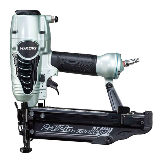
Page 4: Product Name
2. MARKETING OBJECTIVE The new Model NT 65M2 finish nailer is a minor-changed version of the current Model NT 65M. To expand the market share, the Model NT 65M2 is shifted from OEM to manufacturing by ourselves. In addition, the appearance is changed to the one for a next-generation model (Model NR 90AD). -
Page 5: Specifications
Pneumatic tool lubricant (1 oz oil feeder) (Code No. 876212) Grease (ATTOLUB No. 2) (500 g (1.1 lbs.)) (Code No. 317918) 5-2. Nail Selection The Model NT 65M2 utilizes small-head, T-shaped nails (finish nails) collated by adhesive. Applicable nails are shown below. CAUTION: Ensure that nails are as specified in Fig. -
Page 6: Explanation Of The Nailing Action
5-3. Explanation of the Nailing Action To meet the requirements of "ANSI SNT-101-2002", the Model NT 65M2 is equipped with a nailing operation switching device at the valve portion as shown in the figures below. Use SINGLE ACTUATION MECHANISM (SINGLE SEQUENTIAL ACTUATION MECHANISM) or CONTACT ACTUATION MECHANISM in accordance with the work to be performed. -
Page 7: Nail Driving Force
For example, when driving a 65 mm (2-1/2") nail into a hard wood workpiece with the Model NT 65M2, a pressure of about 5.5 kgf/cm (78 psi, 5.4 bar) allows the nailer to drive the nail flush with the surface. -
Page 8: Comparisons With Similar Products
--- 5 ---... -
Page 9: Precautions In Sales Promotion
7. PRECAUTIONS IN SALES PROMOTION In the interest of promoting the safest and most efficient use of the Model NT 65M2 Nailer by all of our customers, it is very important that at the time of sale the salesperson carefully ensures that the buyer seriously recognizes the importance of the contents of the Handling Instructions, and fully understands the meaning of the precautions listed on the Warning Label attached to each tool. -
Page 10: Related Laws And Regulations
7-3. Related Laws and Regulations As nailers and staplers are designed to instantaneously drive nails and staples, there is an ever-present danger of misfiring and subsequent possible serious injury. Accordingly, close attention in handling is absolutely necessary at all times. Carefully ensure that the customer is fully aware of the precautions listed in the Handling Instructions provided with each unit. -
Page 11: Mechanism And Operation Principle
8. MECHANISM AND OPERATION PRINCIPLE 8-1. Mechanism As illustrated in Fig. 3, the Model NT 65M2 can be generally divided into four sections: output section, control valve section, driving section and magazine section. (1) Output section ....(1) The body and the exhaust cover are made of aluminum and their thickness is reduced for weight saving. - Page 12 Control valve section Blow nozzle section Valve Piston [63] O-ring (S-10) [25] Valve Bushing (B) [60] O-ring (1AP-3) [24] Plunger Spring [65] O-ring (S-3) [23] Valve Packing [20] Valve Bushing (A) [68] Plunger [67] Switching device Trigger (C) Ass'y [36] (Change Knob (C) [58]) Valve...
-
Page 13: Operation Principle
8-2. Operation Principle Head valve chamber (1) Before nailing (See Fig. 4 and Fig. 5.) Head Valve Spring [8] 1) When compressed air is fed to the main body, it fills the accumulator ( portion). Air passage Head Valve (A) [10] 2) At the same time, the compressed air flows into Control valve the valve piston lower chamber of the control valve... - Page 14 (3) During return (See Fig. 6 and Fig. 7.) Head Valve 1) When either Pushing Lever (A) [43] or Trigger (C) Spring [8] Head valve chamber Ass'y [36] is released, the Plunger [67] goes down and the compressed air in the accumulator flows into the valve piston lower chamber.
- Page 15 (4) Single actuation mechanism/contact actuation mechanism: (Fig. 8 and Fig. 9) Single/contact actuation mechanism changeover is accomplished by turning the switching device (Change Knob (C) [58]). Single actuation mechanism (Switching device: Accumulator upward position): 1) Immediately after driving the first nail, the control valve should be as shown in Fig.
-
Page 16: Troubleshooting Guide
9. TROUBLESHOOTING GUIDE 9-1. Troubleshooting and Correction Problem Possible cause Inspection method Remedy 1) Nails cannot <Nails> be driven. Magazine is not loaded with Check if the magazine is Use specified nails. specified genuine nails. normally loaded with Remove the abnormal nails specified nails. - Page 17 Problem Possible cause Inspection method Remedy < Output section > Pull the nail feeder Adjust for 5 to 8.5 kgf/cm Air pressure is too low. backward and perform idle (70 --- 120 psi). driving. Check if the driver Piston O-ring is worn or Replace the piston O-ring.
- Page 18 Problem Inspection method Remedy Possible cause 3) Head of a nail Adjuster is improperly Turn the adjuster to the Check if the nails are lowest driven into a adjusted. lowest position and drive a position and drive a nail. workpiece nail.
-
Page 19: Regrinding The Driver Blade
9-2. Regrinding the Driver Blade The tip of the driver blade should be ground as shown in Fig. 10. To grind with a grinder, gradually grind the tip while cooling the ground area with water to prevent it from being excessively heated. Excessive grinding will rapidly reduce the service life of the driver blade. -
Page 20: Possible Causes And Countermeasures For Air Leakage
9-3. Possible Causes and Correction of Air Leakage Air leakage repair locatoin Repair procedure (1) Check the points of the following parts marked by an asterisk for abnormal condition. (2) Next, check the seal parts marked with a double circle for wear, flaw and damage. - Page 21 Possible cause Air leakage point When control valve OFF When control valve ON The Cylinder O-ring (I.D 59.6) [15] is abnormal The Piston Bumper [18] is abnormal ( d or e (C) Blade guide portion is damaged, deformed or cracked). (broken or damaged).
-
Page 22: Disassembly And Reassembly
Apply grease (ATTOLUB No. 2 Code No. 317918) to the O-rings and O-rings' sliding portions. When installing the O-rings, be careful not to damage the O-rings and prevent dirt entry. Oil required: Hitachi pneumatic tool lubricant 30 cc (1 oz) oil feeder (Code No. 877153) 120 cc (4 oz) oil feeder (Code No. -
Page 23: Disassembly And Reassembly Of The Output Section
10-2. Disassembly and Reassembly of the Output Section (1) Disassembly and reassembly of the Exhaust Cover [5], Head Valve (A) [10], Cylinder [13], Piston [12], Piston Bumper [18], etc. (See Fig. 11.) [Tool required] Hex. bar wrenches (5 mm and 4 mm) (a) Disassembly Remove the four Hex. - Page 24 (b) Reassembly Groove of the Disassembly procedures should be followed in the reverse Exhaust Cover [5] order. Note the following points: O-ring (I.D 20.8) [9] Apply grease to the inside of the Cylinder [13], O-ring (I.D 31.7) [11] and the Cylinder O-ring (I.D 59.6) [15] before reassembly.
-
Page 25: Disassembly And Reassembly Of The Control Valve Section
10-3. Disassembly and Reassembly of the Control Valve Section (See Fig. 14.) [Tools required] Flat-blade screwdriver Roll pin puller (3 mm (0.118") dia.) (a) Disassembly Remove the Retaining Ring (E-type) for D6 Shaft [30] with the blade of a screwdriver and pull out Change Knob (C) [58] being careful not to lose the Steel Ball D3.97 [56] and Spring (C) [57]. - Page 26 Push Pull out the Roll Pins D3 x 25 [53] and D3 x 32 [54] with the roll pin puller (3 mm dia.), and take out the control valve in the following manner. Body Ass'y [31] 1) Remove the Exhaust Cover [5] by following the procedure in (1), item 10-2.
- Page 27 (b) Reassembly Disassembly procedures should be followed in the reverse order. Note the following points. Be extremely careful to prevent the entry of foreign particles into the control valve section. Thoroughly apply grease to the O-Rings (I.D 1.8) [66] of the Plunger [67], the O-Rings (P-7) [62] and (1AP-10) [64] of the Valve Piston [63].
-
Page 28: Disassembly And Reassembly Of The Driving Section
10-4. Disassembly and Reassembly of the Driving Section (See Fig. 18.) [Tools required] Hex. bar wrenches (4 mm and 5 mm) Roll pin pullers (3 mm (.118") dia. and 4 mm (.157") dia.) Flat-blade screwdriver with small tip Nylon Nut M5 [84] Handle Arm [85] Hex. -
Page 29: Disassembly And Reassembly Of The Cap And The Magazine Section
Pull out the Roll Pin D4 x 14 [80] with the roll pin puller (4 mm (.157") dia.) so that Guide Plate (A) [75] and Guide Plate (B) [73] can be disassembled. Pull out the Roll Pin D3 x 20 [77] with the roll pin puller (3 mm (.118") dia.) so that the Lock Lever [76] and the Pushing Lever Guide [38] can be removed. - Page 30 (2) Diassembly and reassembly of the magazine section (See Fig. 20.) Magazine Cover [71] Body Nylon Nut M4 [69] Nylon Nut Nylon Nut M4 Ass'y [31] M4 [69] [69] Sleeve Magazine (B) [92] Cover Plate [88] [70] Spacer [93] Nylock Hex. Socket Nail Rail [90] Flat Hd.
-
Page 31: Inspection And Confirmation After Reassembly
NOTE: Before conducting the driving test, turn the Adjuster [42] to the deepest position. Set Change Knob (C) [58] to "single actuation (single sequential actuation)" (see 5-2). Check that the Model NT 65M2 operates by pressing Pushing Lever (A) [43] against a test piece first then pulling Trigger (C) Ass'y [36]. -
Page 32: Standard Repair Time (Unit) Schedules
12. STANDARD REPAIR TIME (UNIT) SCHEDULES Variable 60 min. MODEL Fixed Work Flow NT 65M2 Top Cover Guide Plate (B) Exhaust Cover Guide Plate (A) Gasket Blade Guide Head Valve Spring Magazine (A) Knob O-ring Magazine (B) Plunger Head Valve (A) - Page 33 Hitachi Power Tools LIST NO. E032 PNEUMATIC TOOL PARTS LIST FINISH NAILER 2005 • • Model NT 65M2 (E1)
- Page 34 PARTS NT 65M2 ITEM CODE NO. DESCRIPTION REMARKS USED 949-657 HEX. SOCKET HD. BOLT M6X12 (10 PCS.) 880-515 PLATE 885-673 TOP COVER 885-637 HEX. SOCKET HD. BOLT (W/SP. WASHER) M5X25 885-671 EXHAUST COVER 885-672 GASKET 882-914 HEAD BUMPER 882-913 HEAD VALVE SPRING 883-992 O-RING (I.D 20.8)
- Page 35 PARTS NT 65M2 ITEM CODE NO. REMARKS DESCRIPTION USED HITACHI LABEL 949-539 ROLL PIN D3X25 (10 PCS.) 884-975 ROLL PIN D3X32 949-866 ROLL PIN D3X30 (10 PCS.) 959-155 STEEL BALL D3.97 (10 PCS.) 982-454 SPRING (C) 885-658 CHANGE KNOB (C) 877-763 FEED PISTON O-RING (I.D.14)
-
Page 36: Standard Accessories
STANDARD ACCESSORIES NT 65M2 ITEM CODE NO. DESCRIPTION REMARKS USED 885-549 SAFETY GLASSES 885-676 CASE OPTIONAL ACCESSORIES ITEM CODE NO. DESCRIPTION REMARKS USED 881-768 GRIP TAPE (A) 880-407 TAPE --- 4 --- Printed in Japan 11 -- 05 * ALTERNATIVE PARTS...