
Related Manuals for Panasonic EY6506-U1


Summary of Contents for Panasonic EY6506-U1
-
Page 1: Table Of Contents
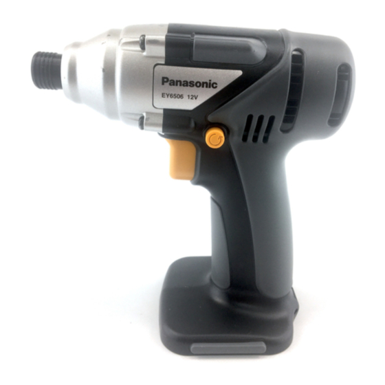
ORDER NO.PTD0310U39C1 Cordless Impact Driver EY6506-U1 SPECIFICATIONS CONTENTS Page Page 1 SCHEMATIC DIAGRAM 4 TROUBLESHOOTING GUIDE 2 WIRING CONNECTION DIAGRAM 5 EXPLODED VIEW 3 DISASSEMBLY/ASSEMBLY INSTRUCTIONS 6 REPLACEMENT PARTS LIST © 2003 Matsushita Electric Works Ltd. All rights reserved. Unauthorized copying and distribution is a... -
Page 2: Schematic Diagram
EY6506-U1 1 SCHEMATIC DIAGRAM 2 WIRING CONNECTION DIAGRAM... -
Page 3: Disassembly/Assembly Instructions
EY6506-U1 3 DISASSEMBLY/ASSEMBLY INSTRUCTIONS IHOW TO DISASSEMBLE MAIN UNIT. Ref. No. 1A Procedure 1A Removal of the Fixation cover and Housing. 1. Remove four screws tightened with the fixation cover and take it out. 2. Remove eight housing screws. Procedure 1A → → → → 1B Ref. - Page 4 EY6506-U1 Procedure 1A → → → → 1B → → → → 1C Ref. No. 1C Removal of the Driving Block. 1. Remove the thrust plate. 2. Take out the planet gears and pins slightly tapping the driving block on the table.
-
Page 5: Troubleshooting Guide
EY6506-U1 4 TROUBLESHOOTING GUIDE (Refer to WIRING CONNECTION DIAGRAM) < TROUBLE > < CHECK > < REMEDY > Does not operate. <CHECK BATTERY PACK.> NO Replace battery pack. → If no less than 12V DC is available across the (+) and (-) terminals, →... - Page 6 EY6506-U1 < TROUBLE > < CHECK > < REMEDY > Does not speed- <CHECK FET.> Repair the contact control. → Even if FET block is defective, it can not be replaced individually. or replace switch Replace whole switch block. →...
-
Page 7: Exploded View
EY6506-U1 5 EXPLODED VIEW... -
Page 8: Replacement Parts List
EY6506-U1 6 REPLACEMENT PARTS LIST NOTE: *B=only available as set *C=available individually Ref.No. Part No. Part Name & Description Remarks Per Unit WEY6506K3078 HOUSING AB SET EY6481L0177 CLICK SPRING WEY6506H4057 FIXATION COVER ASSEMBLY WEY6504L0987 O-RING WEY7300K1167 C-TYPE RING WEY6605L0857 THRUST PLATE...