Table of Contents
Advertisement
www.weslo.com
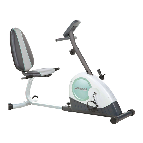
Model No. WLEX31508.0
Serial No.
Write the serial number in the
space above for reference.
Serial Number
QUESTIONS?
If you have questions, or if parts
are damaged or missing, DO NOT
CONTACT THE STORE; please
contact Customer Care.
IMPORTANT: You must note the
product model number and seri-
al number (see the drawing
above) before contacting us:
1-866-699-3756
CALL TOLL-FREE:
Mon.–Fri., 6 a.m.–6 p.m. MT
Sat. 8 a.m–4 p.m. MT
ON THE WEB:
www.wesloservice.com
CAUTION
Read all precautions and instruc-
tions in this manual before using
this equipment. Keep this manual
for future reference.
Decal
USERʼS MANUAL
Advertisement
Table of Contents

Related Manuals for Weslo pursuit CT 3.8 R


Summary of Contents for Weslo pursuit CT 3.8 R
- Page 1 USERʼS MANUAL Model No. WLEX31508.0 Serial No. Write the serial number in the space above for reference. Serial Number Decal QUESTIONS? If you have questions, or if parts are damaged or missing, DO NOT CONTACT THE STORE; please contact Customer Care.
-
Page 2: Table Of Contents
Apply the decal in the location shown. Note: The decal(s) may not be shown at actual size. WESLO is a registered trademark of ICON IP, Inc. -
Page 3: Important Precautions
IMPORTANT PRECAUTIONS WARNING: To reduce the risk of serious injury, read all important precautions and instructions in this manual and all warnings on your exercise cycle before using your exercise cycle. ICON assumes no responsibility for personal injury or property damage sustained by or through the use of this product. -
Page 4: Before You Begin
BEFORE YOU BEGIN Thank you for selecting the new WESLO PURSUIT model number and serial number before contacting ® CT 3.8 R exercise cycle. Cycling is an effective exer- us. The model number and the location of the serial cise for increasing cardiovascular fitness, building number decal are shown on the front cover of this endurance, and toning the body. -
Page 5: Assembly
ASSEMBLY To hire an authorized service technician to assemble the exercise cycle, call 1-800-445-2480. Assembly requires two persons. Place all parts of the exercise cycle in a cleared area and remove the pack- ing materials. Do not dispose of the packing materials until assembly is completed. In addition to the included tool(s), assembly requires a Phillips screwdriver , an adjustable wrench... - Page 6 To make assembly easier, read the information on page 5 before you begin. Turn the Front Stabilizer (2) so that the large holes are facing the Frame (1). Attach the Front Stabilizer (2) to the Frame (1) with two M10 x 60mm Button Screws (33). Large Holes 2.
-
Page 7: 14, 15) With Four M6 X 35Mm Button Screws
4. Attach the Left and Right Seat Brackets (14, 15) to the Seat Frame (5) with two M8 x 125mm Bolts (62), four M8 Washers (54), and two M8 Locknuts (10) as shown. Do not tighten the Locknuts yet. 5. Attach a Seat Handle (59) to the round tube on the Left Seat Bracket (14) with two M6 x 30mm Button Bolts (64), two M6 Curved Washers (69), and two M6 Locknuts (63). -
Page 8: 61) And Four M6 Washers (68
7. Attach the Seat (12) to the Seat Brackets (14, 15) with four M6 x 35mm Button Screws (61) and four M6 Washers (68). 8. While another person holds the Upright (13) in the position shown, connect the Extension Wire (52) to the Reed Switch Wire (43). - Page 9 9. Attach the Handlebar (53) to the Upright (13) with two M8 x 65mm Button Bolts (72), two M8 Curved Washers (46), and two M8 Locknuts (10). 10. The Console (16) requires four “AA” batteries Screw (not included); alkaline batteries are recom- Battery Cover mended.
- Page 10 12. Identify the Left Pedal (24), which is marked with an “L” sticker. Using an adjustable wrench, firmly tighten the Left Pedal (24) counterclockwise into the left arm of the Crank (21). Tighten the Right Pedal (not shown) clockwise into the right arm of the Crank (not shown). IMPORTANT: Tighten both pedals as firmly as possible.
-
Page 11: How To Use The Exercise Cycle
HOW TO USE THE EXERCISE CYCLE HOW TO ADJUST THE SEAT FRAME FEATURES OF THE CONSOLE For effective exercise, the seat should be in the proper position. As you pedal, there should be a slight bend in your knees when the pedals are in the most forward position. - Page 12 HOW TO USE THE MANUAL MODE When you turn Indicators on the console, 1. Turn on the console. the scan mode will be selected To turn on the console, press the On/Reset button automatically. or begin pedaling. The entire display and the pace One indicator will guide will light for a moment;...
- Page 13 4. Measure your heart rate if desired. 3. Begin pedaling to start the workout. To measure your Each pace workout consists of 30 one-minute seg- heart rate, stop ments. One target pace is programmed for each pedaling and segment. Any time the target pace is about to place your thumb change, the display will flash for a few seconds to on the pulse sen-...
-
Page 14: Maintenance And Troubleshooting
MAINTENANCE AND TROUBLESHOOTING HOW TO ADJUST THE DRIVE BELT Inspect and tighten all parts of the exercise cycle reg- ularly. Replace any worn parts immediately. If you can feel the pedals slip while you are pedaling, To clean the exercise cycle, use a damp cloth and a even when the resistance is at the highest level, the small amount of mild detergent. -
Page 15: Exercise Guidelines
EXERCISE GUIDELINES WARNING: Burning Fat—To burn fat effectively, you must exer- cise at a low intensity level for a sustained period of Before beginning time. During the first few minutes of exercise, your this or any exercise program, consult your body uses carbohydrate calories for energy. - Page 16 SUGGESTED STRETCHES The correct form for several basic stretches is shown at the right. Move slowly as you stretch—never bounce. 1. Toe Touch Stretch Stand with your knees bent slightly and slowly bend forward from your hips. Allow your back and shoulders to relax as you reach down toward your toes as far as possible.
- Page 17 NOTES...
-
Page 18: Part List
PART LIST—Model No. WLEX31508.0 R0209A Key No. Qty. Description Key No. Qty. Description Frame Magnet Front Stabilizer Flywheel Axle – Not Used M10 Small Washer Front Stabilizer Cap M4 x 25mm Screw Seat Frame M8 Split Washer Rear Stabilizer Reed Switch/Wire Seat Handle Cap Crank Bearing Set Rear Stabilizer Cap... -
Page 19: Exploded Drawing
EXPLODED DRAWING—Model No. WLEX31508.0 R0209A... -
Page 20: Ordering Replacement Parts
ORDERING REPLACEMENT PARTS To order replacement parts, please see the front cover of this manual. To help us assist you, be prepared to provide the following information when contacting us: • the model number and serial number of the product (see the front cover of this manual) •...