
Related Manuals for Fluke 88 V


Summary of Contents for Fluke 88 V
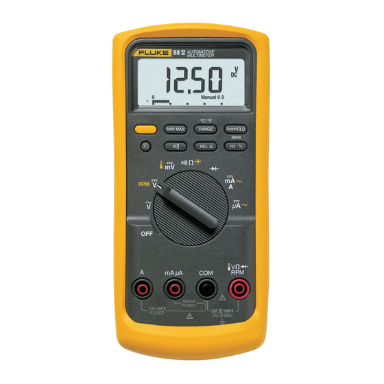
- Page 1 99 Washington Street Melrose, MA 02176 Fax 781-665-0780 ® TestEquipmentDepot.com Model 88 V Automotive Multimeter Users Manual...
-
Page 2: Table Of Contents
Table of Contents Title Page Introduction ........................1 Contacting Fluke ........................ 1 Safety Information......................1 The Meter's Features......................5 Power-Up Options......................13 Automatic Power-Off..................... 13 Input Alert Feature ..................... 13 Making Measurements ...................... 14 Measuring AC and DC Voltage ..................14 Measuring Temperature .................... - Page 3 Model 88 V Users Manual Measuring Duty Cycle ....................29 Measuring Pulse Width....................30 Bar Graph .......................... 30 Zoom Mode (Power Up Option Only)................30 Uses for the Zoom Mode ....................31 HiRes Mode ........................31 MIN MAX Recording Mode ....................31 Smooth Feature (Power Up Option Only).................
- Page 4 (continued) Contents Service and Parts ......................60 Specifications........................66 General Specifications....................66 Detailed Specifications ....................67...
- Page 5 List of Tables Table Title Page Electrical Symbols........................4 88 V Automotive Multimeter Front Controls ................5 Input Terminals ......................... 6 Rotary Switch Positions ......................7 Pushbuttons ..........................8 Display Features ........................11 Functions and Trigger Levels for Frequency Measurements ..........28 MIN MAX Functions ........................
- Page 6 Model 88 V Users Manual Frequency Counter Sensitivity and Trigger Levels ..............72 Electrical Characteristics of the Terminals................73 Min Max Recording Specifications ................... 74...
- Page 7 List of Figures Figure Title Page 88 V Automotive Multimeter Front .................... 5 Measuring AC and DC Voltage ....................14 Testing for Continuity ........................ 17 Measuring Resistance ......................19 Measuring Capacitance ......................21 Testing a Diode ......................... 23 Measuring Current ........................26 Components of Duty Cycle Measurements................
- Page 8 Model 88 V Users Manual Measuring the No-Load Voltage of a Battery................55 Testing for Continuity in a Switch ..................... 57 Testing the Current Fuses ......................59 Battery and Fuse Replacement....................61 Replaceable Parts........................64 viii...
-
Page 9: Introduction
EN61010-1:2001 Meter. • ANSI/ISA S82.01-2004 • CAN/CSA C22.2 No. 1010.1:2004 The Model 88 V Automotive Multimeter (“the Meter”) is a • hand-held, battery-operated measurement device used for UL61010-1 • voltage, continuity, resistance, current, diode, capacitance, Measurement Category III, 1000 V, Pollution... - Page 10 Model 88 V Users Manual XWWarning • Do not apply more than the rated voltage, as marked on the Meter, between the To avoid possible electric shock or personal terminals or between any terminal and injury, follow these guidelines: earth ground.
- Page 11 Automotive Multimeter Safety Information • XWCaution Do not operate the Meter around explosive gas, vapor, or dust. To avoid possible damage to the Meter or to • Use only a single 9 V battery, properly the equipment under test, follow these installed in the Meter case, to power the guidelines: Meter.
-
Page 12: Electrical Symbols
Model 88 V Users Manual Table 1. Electrical Symbols AC (Alternating Current) Earth ground DC (Direct Current) Fuse Hazardous voltage Conforms to European Union directives. Risk of Danger. Important information. Conforms to relevant Canadian Standards Association See Manual. directives. Battery. Low battery when displayed. -
Page 13: The Meter's Features
Automotive Multimeter The Meter's Features The Meter's Features Table 2. 88 V Automotive Multimeter Front Controls Tables 2 through 6 briefly describe the Meter's features. Number Description Display Pushbuttons Rotary Switch MIN MAX RANGE AutoHOLD Input Terminals Hz % 400mA... -
Page 14: Input Terminals
Model 88 V Users Manual Table 3. Input Terminals Terminal Description Input for 0 A to 10.00 A current measurements (20 A overload for 30 seconds maximum), current frequency, duty cycle, and pulse width measurements. µ Input for 0 µA to 400 mA current measurements (600 mA for 18 hrs.), current frequency, duty cycle, and pulse width. -
Page 15: Rotary Switch Positions
Automotive Multimeter The Meter's Features Table 4. Rotary Switch Positions Switch Position Function Any Position When the Meter is turned on, the Meter model number briefly appears on the display. AC voltage measurement DC voltage measurement for RPM o, press again for RPM n. Press 600 mV dc voltage range (T). -
Page 16: Pushbuttons
Model 88 V Users Manual Table 5. Pushbuttons Switch Button Function Position Selects capacitance Selects temperature g K L Selects measurement of RPM o or RPM n (Yellow) Switches between dc and ac current Switches between dc and ac current Power-up Disables automatic power-off feature (Meter normally powers off in 30 minutes). - Page 17 Automotive Multimeter The Meter's Features Table 5. Pushbuttons (cont.) Switch Function Button Position Any switch Switches between the ranges available for the selected function. To return to autoranging, hold the position button down for 1 second. Switches between °C and °F when temperature is selected. 5___ Power-up Enables the Meter’s smoothing feature.
- Page 18 Model 88 V Users Manual Table 5. Pushbuttons (cont.) Switch Button Function Position Turns the continuity beeper on and off Continuity Switches between Peak (250 µs) and Normal (100 ms) response times. MIN MAX recording Toggles the meter to trigger on positive or negative slope.
-
Page 19: Display Features
Automotive Multimeter The Meter's Features Table 6. Display Features Indication Number Feature Smoothing is active. Indicates negative readings. In relative mode, this sign indicates that the present input is less than the stored reference. Indicates the presence of a high voltage input. Appears if the input voltage is 30 V or greater (ac or dc). - Page 20 Model 88 V Users Manual Indication Number Feature Indication Number Feature Amperes (amps), Microamp, The Meter is in autorange A, µA, mA Milliamp mode and automatically Auto selects the range with the best Volts, Millivolts V, mV resolution. µF, nF...
-
Page 21: Power-Up Options
Automotive Multimeter The Meter's Features Input Alert Feature Indication Number Feature If a test lead is plugged into the mA/µA or A terminal, but Overload condition is the rotary switch is not set to the correct current position, detected. the beeper warns you by making a chirping sound and the Error Messages display flashes “LEAd”. -
Page 22: Making Measurements
Model 88 V Users Manual Making Measurements AC Voltage The following sections describe how to take Switch Box measurements with the Meter. MIN MAX RANGE AutoHOLD Measuring AC and DC Voltage Hz % The Meter's voltage ranges are 600.0 mV, 6.000 V, 60.00 V, 600.0 V, and 1000 V. -
Page 23: Measuring Temperature
Automotive Multimeter Making Measurements Press A to enter temperature mode. Measuring Temperature Push C to choose Celsius or Fahrenheit. The Meter measures the temperature of a type-K thermocouple (included). Choose between degrees Celsius (°C) or degrees Fahrenheit (°F) by pushing C. XW Caution To avoid possible damage to the Meter or other equipment, remember that while the... -
Page 24: Testing For Continuity
Model 88 V Users Manual Testing for Continuity XWCaution To avoid possible damage to the Meter or to the equipment under test, disconnect circuit power and discharge all high-voltage capacitors before testing for continuity. The continuity test features a beeper that sounds as long as a circuit is complete. -
Page 25: Testing For Continuity
Automotive Multimeter Making Measurements For in-circuit tests, turn circuit power off. (closed) Activates (open) continuity beeper MIN MAX RANGE AutoHOLD RANGE AutoHOLD MIN MAX Hz % Hz % 400mA 400mA FUSED 10A MAX FUSED 10A MAX FUSED FUSED ayg03.eps Figure 3. Testing for Continuity... -
Page 26: Measuring Resistance
Model 88 V Users Manual Measuring Resistance The following are some tips for measuring resistance: • XWCaution The measured value of a resistor in a circuit is often different from the resistor's rated value. • To avoid possible damage to the •... -
Page 27: Measuring Resistance
Automotive Multimeter Making Measurements In-Circuit Resistance Measurements Isolating a Potentiometer Circuit Power Disconnect RANGE AutoHOLD MIN MAX Hz % Isolating a Resistor 400mA FUSED 10A MAX FUSED Disconnect aug06f.eps Figure 4. Measuring Resistance... -
Page 28: Using Conductance For High Resistance Or Leakage Tests
Model 88 V Users Manual • Using Conductance for High Resistance or There is normally a residual conductance reading with the test leads open. To ensure accurate Leakage Tests readings, use the relative (REL) mode to subtract the Conductance, the inverse of resistance, is the ability of a residual value. -
Page 29: Measuring Capacitance
Automotive Multimeter Making Measurements Measuring Capacitance XWCaution Select To avoid possible damage to the Meter or to Capacitance the equipment under test, disconnect circuit MIN MAX RANGE AutoHOLD power and discharge all high-voltage Hz % capacitors before measuring capacitance. Use the dc voltage function to confirm that the capacitor is discharged. -
Page 30: Testing Diodes
Model 88 V Users Manual Testing Diodes A short beep sounds if the diode is good (<0.85 V). A continuous beep sounds if the reading is ≤0.100 V. This XWCaution reading would indicate a short circuit. The display shows To avoid possible damage to the Meter or to “OL”... -
Page 31: Testing A Diode
Automotive Multimeter Making Measurements Forward Bias Reverse Bias Typical Reading RANGE AutoHOLD RANGE AutoHOLD MIN MAX MIN MAX Hz % Hz % Single Beep 400mA 400mA FUSED FUSED 10A MAX 10A MAX FUSED FUSED Shorted Open Bad Diode Bad Diode MIN MAX RANGE AutoHOLD... -
Page 32: Measuring Dc Or Ac Current
Model 88 V Users Manual The Meter's current ranges are 600.0 µA, 6000 µA, Measuring DC or AC Current 60.00 mA, 400.0 mA, 6000 mA, and 10 A. XWWarning To measure current, refer to Figure 7 and proceed as To avoid possible electric shock or personal... - Page 33 Automotive Multimeter Making Measurements Break the circuit path to be tested. Touch the black probe to the more negative side of the break; touch the red probe to the more positive side of the break. Reversing the leads will produce a negative reading, but will not damage the Meter.
-
Page 34: Measuring Current
Model 88 V Users Manual Total current to circuit Circuit Power: OFF to connect meter. ON for measurement. OFF to disconnect meter. MIN MAX RANGE AutoHOLD Hz % Current through one component 400mA FUSED 10A MAX FUSED ayg07f.eps Figure 7. Measuring Current Test Equipment Depot - 800.517.8431 - 99 Washington Street Melrose, MA 02176... -
Page 35: Measuring Frequency
Automotive Multimeter Making Measurements The following are some tips for measuring frequency: Measuring Frequency • If a reading shows as 0 Hz or is unstable, the input The Meter measures the frequency of a voltage or current signal may be below or near the trigger level. You can signal by counting the number of times the signal crosses a usually correct these problems by selecting a lower threshold level each second. -
Page 36: Functions And Trigger Levels For Frequency Measurements
Model 88 V Users Manual Table 7. Functions and Trigger Levels for Frequency Measurements Approximate Function Range Typical Application Trigger Level 6 V, 60 V, ± 5 % of scale Most signals. 600 V, 1000 V High-frequency 5 V logic signals. (The dc-coupling of the L function can 600 mV ±... -
Page 37: Measuring Duty Cycle
Automotive Multimeter Making Measurements Measuring Duty Cycle frequency function, you can change the slope for the Meter's counter by pressing E. Duty cycle (or duty factor) is the percentage of time a signal is above or below a trigger level during one cycle For 5 V logic signals, use the 6 V dc range. -
Page 38: Measuring Pulse Width
Model 88 V Users Manual Measuring Pulse Width In the 60 V range, for example, the major divisions on the scale represent 0, 15, 30, 45, and 60 V. An input of -30 V For a periodic waveform (its pattern repeats at equal time... -
Page 39: Uses For The Zoom Mode
Changing the response time erases all recorded readings. high-resolution (HiRes), 4-1/2 digit mode. Readings are Model 88 V has 100 millisecond, and 250 µs (peak) displayed at 10 times the normal resolution with a response times. The 250 µs response time is indicated by maximum display of 19,999 counts. -
Page 40: Smooth Feature (Power Up Option Only)
Model 88 V Users Manual average reading is useful for smoothing out unstable Smooth Feature (Power Up Option Only) inputs, calculating power consumption, or estimating the When the input signal changes rapidly, “smoothing” percentage of time a circuit is active. -
Page 41: Min Max Functions
Automotive Multimeter Smooth Feature (Power Up Option Only) Table 8. MIN MAX Functions Button MIN MAX Function Enter MIN MAX recording mode. The Meter is locked in the range displayed before you entered MIN MAX mode. (Select the desired measurement function and range before entering MIN MAX.) The Meter beeps each time a new minimum or maximum value is recorded. -
Page 42: Autohold Mode
Model 88 V Users Manual AutoHOLD Mode Note The bar graph continues to display the actual XWWarning voltage. To avoid possible electric shock or personal Using the Meter for Automotive injury, do not use AutoHOLD mode to Applications determine that circuits are without power. The... -
Page 43: Measuring Rpm
Automotive Multimeter Using the Meter for Automotive Applications • Measuring RPM If the meter reading is too high or is unstable, move to the next V range by pressing C once. RPM can be measured in either the dc volts or ac volts •... - Page 44 Model 88 V Users Manual Connect output plug of Inductive Pickup in the input terminals shown. Make sure the (-) plug is in COM and the (+) is in RPM. See Figure 9. Turn rotary switch to For 4-cycle engines that fire once every other revolution, press A once to select RPMo.
-
Page 45: Measuring Rpm With Inductive Pickup
Automotive Multimeter Using the Meter for Automotive Applications MIN MAX RANGE AutoHOLD Hz % 400mA FUSED 10A MAX FUSED ayg21f.eps Figure 9. Measuring RPM with Inductive Pickup... -
Page 46: Testing Map Or Bp/Map Sensors With Frequency Output
Model 88 V Users Manual Note Testing MAP or BP/MAP Sensors with Frequency Output Frequency measurements can be made on voltage (V dc, V ac, or mV dc) or current inputs To use the Frequency function to check barometric (mA/A ac or dc). In automotive applications,... -
Page 47: Testing Map Or Bp/Map Sensors With Frequency Output
Automotive Multimeter Using the Meter for Automotive Applications MIN MAX RANGE AutoHOLD Hz % 400mA FUSED 10A MAX FUSED ayg22f.eps Figure 10. Testing MAP or BP/MAP Sensors with Frequency Output... -
Page 48: Measuring Internal Resistance Of An Ignition Coil
Model 88 V Users Manual XWWarning Measuring Internal Resistance of an Ignition Coil To avoid possible electric shock or damage to When measuring resistance, be sure that the contact the Meter turn engine off before making between the probes and the circuit is clean. Dirt, oil, paint, measurements. -
Page 49: Measuring Internal Resistance On An Ignition Coil
Automotive Multimeter Using the Meter for Automotive Applications MIN MAX RANGE AutoHOLD MIN MAX RANGE AutoHOLD Hz % Hz % 400mA 400mA FUSED FUSED 10A MAX 10A MAX FUSED FUSED ayg11f.eps Figure 11. Measuring Internal Resistance on an Ignition Coil... -
Page 50: Measuring Pulse Width On A Port Fuel Injector
Model 88 V Users Manual Measuring Pulse Width on a Port Fuel Injector In Pulse Width (and Duty Cycle), the meter defaults to (-) trigger slope; (time signal is low). Press E (± TRIGGER) to toggle between (±) trigger slopes. The slope is indicated by the + or - sign next to “Trig”... -
Page 51: Measuring Pulse Width On A Port Fuel Injector
Automotive Multimeter Using the Meter for Automotive Applications MIN MAX RANGE AutoHOLD Hz % 400mA FUSED 10A MAX FUSED ayg12f.eps Figure 12. Measuring Pulse Width on a Port Fuel Injector... -
Page 52: Testing Ripple Voltage On An Alternator
Model 88 V Users Manual Testing Ripple Voltage on an Alternator Ripple voltage or ac voltage can be measured by switching your meter to ac and connecting the black lead to a good ground and the red lead to the “BAT” terminal on the back of the alternator (not at the battery). -
Page 53: Testing Ripple Voltage On An Alternator
Automotive Multimeter Using the Meter for Automotive Applications MIN MAX RANGE AutoHOLD Hz % 400mA FUSED 10A MAX FUSED ayg16f.eps Figure 13. Testing Ripple Voltage on an Alternator... -
Page 54: Measuring Voltages On A Typical Oxygen Sensor
Model 88 V Users Manual Measuring Voltages on a Typical Oxygen Sensor Watch the bar graph sweep as oxygen voltage changes. Depending on the driving conditions, the oxygen voltage will rise and fall, but it usually averages around 0.450 V dc. -
Page 55: Measuring Voltages On A Typical Oxygen Sensor
Automotive Multimeter Using the Meter for Automotive Applications MIN MAX RANGE AutoHOLD Hz % 400mA FUSED 10A MAX FUSED ayg14f.eps Figure 14. Measuring Voltages on a Typical Oxygen Sensor... -
Page 56: Measuring Starter Circuit Voltage Drop
Model 88 V Users Manual Measuring Starter Circuit Voltage Drop Since AutoHOLD ignores readings of 0, it will retain the voltage drop after you quit cranking. Insert test leads in the input terminals shown in Figure Set the rotary switch to . -
Page 57: Measuring Starter Circuit Voltage Drop
Automotive Multimeter Using the Meter for Automotive Applications MIN MAX RANGE AutoHOLD Hz % – 400mA FUSED 10A MAX FUSED ayg17f.eps Figure 15. Measuring Starter Circuit Voltage Drop... -
Page 58: Testing The Throttle Position Sensor Voltage
Model 88 V Users Manual Testing the Throttle Position Sensor Resistance Testing the Throttle Position Sensor Voltage Insert test leads in the input terminals shown in Figure The throttle position sensor sends a signal to the computer indicating the position of the throttle. To test the throttle position sensor: Set the rotary switch to N. -
Page 59: Testing The Throttle Position Sensor Resistance
Automotive Multimeter Using the Meter for Automotive Applications MIN MAX RANGE AutoHOLD Hz % 400mA FUSED 10A MAX FUSED ayg15f.eps Figure 16. Testing the Throttle Position Sensor Resistance... -
Page 60: Isolating A Circuit Causing A Current Drain
Model 88 V Users Manual XWCaution Isolating a Circuit Causing a Current Drain Do not crank the engine or operate Insert the test leads in the input terminals shown in accessories that draw more than 10 A. You Figure 17. -
Page 61: Isolating Circuit Causing Current Drain
Automotive Multimeter Using the Meter for Automotive Applications MIN MAX RANGE AutoHOLD Hz % 400mA FUSED 10A MAX FUSED ayg18f.eps Figure 17. Isolating Circuit Causing Current Drain... -
Page 62: Measuring System Voltage
Model 88 V Users Manual Table 9. Battery Charge Voltages Measuring System Voltage Bleed the surface charge from the battery by turning the Voltage % Charge headlights on for 1 minute. Measure the voltage across the 12.60 to 12.72 V battery terminal with the lights off. -
Page 63: Measuring The No-Load Voltage Of A Battery
Automotive Multimeter Using the Meter for Automotive Applications MIN MAX RANGE AutoHOLD Hz % 400mA FUSED 10A MAX FUSED ayg19f.eps Figure 18. Measuring the No-Load Voltage of a Battery... -
Page 64: Testing For Continuity In A Switch
Model 88 V Users Manual XWCaution Testing for Continuity in a Switch To avoid possible damage to the meter or to A continuity test verifies that you have a closed circuit. The equipment under test, disconnect the power continuity function detects opens or shorts as fast as 1 to the circuit under test and discharge all high millisecond. -
Page 65: Testing For Continuity In A Switch
Automotive Multimeter MIN MAX RANGE AutoHOLD Hz % 400mA FUSED 10A MAX FUSED ayg20f.eps Figure 19. Testing for Continuity in a Switch... -
Page 66: Maintenance
Model 88 V Users Manual Testing the Fuse Maintenance If a test lead is plugged into the mA/µA or A terminal and XWWarning the rotary switch is turned to a non-current function, the Meter chirps and flashes “LEAd” if the fuse associated To avoid possible electric shock or personal with that current terminal is good. -
Page 67: Replacing The Battery
Automotive Multimeter Maintenance Replacing the Battery Good F2 fuse: 00.0 Ω to 00.5 Ω Replace the battery with a 9 V battery (NEDA A1604, 6F22, or 006P). Replace fuse: OL RANGE AutoHOLD MIN MAX Hz % Warning To avoid false readings, which could lead to Touch top half of input contacts possible electric shock or personal injury,... -
Page 68: Replacing The Fuses
Model 88 V Users Manual Replacing the Fuses Verify that the rotary switch and the circuit board switch are in the OFF position. Referring to Figure 21, examine or replace the Meter's fuses as follows: Replace the case top, ensuring that the gasket is... -
Page 69: Battery And Fuse Replacement
Automotive Multimeter Service and Parts ayg33f.eps Figure 21. Battery and Fuse Replacement... -
Page 70: Replacement Parts
448456 J1-2 Elastomeric Connector 817460 MP10-11 Foot, Non-Skid 824466 Shield, Top 2073906 Shield, Bottom 2074025 Case Top (PAD XFER) with Window 88 V 2115202 Case Bottom 2073871 Knob, Switch (PAD XFER) 2100482 Detent, Knob 822643 MP13 Shock Absorber 828541 MP14... - Page 71 Access Door Fastener 948609 LCD, 4.5 DIGIT,TN, Transflective, Bar Graph, OSPR80 2065213 Light pipe 2074057 Keypad 2105884 2166623 Model 88 V Automotive Multimeter Users Manual (this manual) 2279006 Model 88 V Automotive Multimeter Quick Reference Card 2278999 CD ROM, 88...
-
Page 72: Replaceable Parts
Model 88 V Users Manual Holster MP31 MP15 Tilt Stand H1 (4) MP10 MP11 MP22 H5, 6 ayg34f.eps Figure 22. Replaceable Parts Test Equipment Depot - 800.517.8431 - 99 Washington Street Melrose, MA 02176 FAX 781.665.0780 - TestEquipmentDepot.com... -
Page 73: Accessories
RPM80 Inductive Clamp (included) TL224 Sure Grip Test Lead Set, Heat-Resistant Silicone (included) TL71 Silicone Insulated Test Lead Set TP220 Sure Grip Test Probe Set (included) TPAK ToolPak Magnetic Hanger (included) Fluke accessories are available from an authorized Fluke distributor. -
Page 74: Specifications
Model 88 V Users Manual Specifications General Specifications Maximum Voltage between any Terminal and Earth Ground:............1000 V Fuse Protection for mA or µA inputs: ....44/100 A, 1000 V FAST Fuse W Fuse Protection for A input: ........11 A, 1000 V FAST Fuse Display: ................Digital: 6000 counts updates 4/sec;... -
Page 75: Detailed Specifications
Automotive Multimeter Specifications Weight:................12.5 oz (355 g) Weight with Holster and Flex-Stand:......22.0 oz (624 g) Safety: ................Complies with ANSI/ISA S82.01-2004, CSA 22.2 No. 1010.1:2004 to 1000 V Overvoltage Category III, IEC 664 to 600 V Overvoltage Category IV. UL listed to UL61010-1. Licensed by TÜV to EN61010-1. Detailed Specifications For all detailed specifications: Accuracy is given as ±... -
Page 76: Dc Voltage, Resistance, And Conductance Function Specifications
Model 88 V Users Manual Table 13. DC Voltage, Resistance, and Conductance Function Specifications Function Range Resolution Accuracy ± (0.1 % + 1) 6.000 V 0.001 V ± (0.1 % + 1) 60.00 V 0.01 V ± (0.1 % + 1) 600.0 V... -
Page 77: Current Function Specifications
Automotive Multimeter Specifications Table 15. Current Function Specifications Function Range Resolution Accuracy Burden Voltage (typical) ± (1.2 % + 2) 60.00 mA 0.01 mA 1.8 mV/mA ± (1.2 % + 2) 400.0 mA 0.1 mA 1.8 mV/mA (45 Hz to 2 kHz) ±... -
Page 78: Capacitance And Diode Function Specifications
Model 88 V Users Manual Table 16. Capacitance and Diode Function Specifications Function Range Resolution Accuracy ± (1 % + 2) 10.00 nF 0.01 nF ± (1 % + 2) 100.0 nF 0. 1 nF 1.000 µF 0.001 µF ± (1 % + 2) 10.00 µF... -
Page 79: Frequency Counter Specifications
Automotive Multimeter Specifications Table 17. Frequency Counter Specifications Pulse Width Range Resolution Function Range Resolution Accuracy (ms) (ms) ± (0.01 % + 1) Frequency 199.99 0.01 Hz 1999.9 ± (0.01 % + 1) (0.5 Hz to 200 kHz, 1999.9 0.1 Hz 5.00 0.01 pulse width >... -
Page 80: Frequency Counter Sensitivity And Trigger Levels
Model 88 V Users Manual Table 18. Frequency Counter Sensitivity and Trigger Levels Minimum Sensitivity Approximate Trigger Level Input Range (DC Voltage Function) 5 Hz - 20 kHz 0.5 Hz - 200 kHz 600 mV dc 70 mV (to 400 Hz) -
Page 81: Electrical Characteristics Of The Terminals
Automotive Multimeter Specifications Table 19. Electrical Characteristics of the Terminals Common Mode Input Impedance Overload Rejection Ratio Function Normal Mode Rejection (nominal) Protection (1 kΩ unbalance) 1000 V 10 MΩ < 100 pF > 120 dB at dc, > 60 dB at 50 Hz or 60 Hz 50 Hz or 60 Hz 1000 V 10 MΩ... -
Page 82: Min Max Recording Specifications
Model 88 V Users Manual Table 20. Min Max Recording Specifications Nominal Response Accuracy Specified accuracy ± 12 counts for changes > 200 ms in duration 100 ms to 80 % (dc functions) Specified accuracy ± 40 counts for changes > 350 ms and inputs > 25 % of range...