Nortel T7406E Installation And Configuration Manual
Hide thumbs
Also See for T7406E:
- User manual (34 pages) ,
- Quick reference card (2 pages) ,
- User manual (29 pages)

Related Manuals for Nortel T7406E


Summary of Contents for Nortel T7406E
- Page 1 T7406E Cordless Handset Installation and Configuration Guide T7406E Business Communications Manager Document Status: Standard Document Version: 01.02 Part Code: NN40110-301 Date: October 2007...
- Page 2 Nortel Networks. Trademarks Nortel, the Nortel logo, and the Globemark are trademarks of Nortel Networks. Microsoft, MS, MS-DOS, Windows, and Windows NT are registered trademarks of Microsoft Corporation. All other trademarks and registered trademarks are the property of their respective owners.
-
Page 3: Table Of Contents
Base station features ..........26 T7406E Cordless Handset Installation and Configuration Guide... - Page 4 Contents LED status indicators ..........28 DIP switches .
- Page 5 Scanning the base station radio frequency ..............45 Scanning the environment.....................46 Installing the USB-to-UART bridge controller drivers ............47 Upgrading the base station firmware ................48 Upgrading the handset firmware ...................49 Verifying the firmware version ..................50 T7406E Cordless Handset Installation and Configuration Guide...
- Page 6 Task List NN40110-301 NN40110-301...
-
Page 7: How To Get Help
To access some Nortel Technical Solutions Centers, you can use an Express Routing Code (ERC) to quickly route your call to a specialist in your Nortel product or service. To locate the ERC for your product or service, go to: http://www.nortel.com/erc... - Page 8 How to get help NN40110-301 NN40110-301...
-
Page 9: What's New
T7406E Cordless Handset User Guide (NN40110-110). Choice of ring tones You can chose one of eight ring tones. For more information on ring tones, refer to the T7406E Cordless Handset User Guide (NN40110-110). T7406E Cordless Handset Installation and Configuration Guide... -
Page 10: 20-Name Directory
40 seconds. To charge or top-up the battery, place the handset in the charging cradle. For more information on the battery level indicator, refer to the T7406E Cordless Handset User Guide (NN40110-110). -
Page 11: Usb To Uart Bridge Controller
Chapter 1 What’s new USB to UART bridge controller You can upgrade the T7406E firmware when new versions become available. Use the USB to UART bridge controller, along with the FlashLoader program, to upgrade the firmware. For more information on how to upgrade your T7406E cordless handset system, refer to Chapter 6, “Upgrading the firmware,”... - Page 12 Chapter 1 What’s new NN40110-301 NN40110-301...
-
Page 13: Introduction
Firmware upgrade components The T7406E connects to the Nortel KSU. Up to four lines run from the KSU to the T7406E base station. Each base station, of which there can be a maximum of two within 10 meters of each other, can accommodate a maximum of four handsets. -
Page 14: Installation Considerations
With the correct selection of the T7406E operating band, the RF LAN operating at 2.4 GHz does not pose an operating issue for T7406E, nor does the T7406E pose issues for the RF LAN with respect to data transmission capabilities. However, there can be instances where the T7406E user can hear an occasional audio click when operating in an RF LAN environment. -
Page 15: Operational Parameters
The indoor range of the T7406E varies based on the type of office environment. The outdoor clear-line-of-sight range is 350 meters (1000 feet). This range can vary with differing environments. -
Page 16: Environment Layout Considerations
(RFLAN), extensive machinery, computer equipment, and other cordless phones or wireless devices Place the antenna correctly to endure that the performance of the T7406E is at its best. Pick a central location and mount the antenna using the following guidelines: •... - Page 17 Chapter 2 Introduction Office facilities The T7406E can also be used in business premises 46 m (150 ft) with larger square footage and that have an interior layout that has a higher concentration of physical barriers. Full radio coverage at these facilities takes more planning to work around possible barriers.
-
Page 18: Handset Overview
T7406E. For this type of environment, contact your authorized Nortel distributor to discuss alternatives. Handset overview The T7406E handset automatically links with the base station by searching for the base station signal after you complete following tasks: • charge the battery •... -
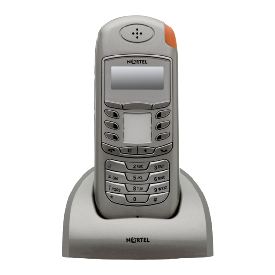
Page 19: Handset Features
Chapter 2 Introduction Handset features Figure 1 on page 20 shows the layout of the handset function keys, softkeys, and keypad, as well as additional handset features. T7406E Cordless Handset Installation and Configuration Guide... - Page 20 Chapter 2 Introduction Figure 1 Handset features Call-hold/message waiting indicator Flashes when a call is on hold or when a message is waiting. Indicator keys Shows the call information and Start or cancel a handset status icons, and guides feature. you while using features.
-
Page 21: Indicator Keys
At any menu level, press the Release key to return to the previous menu level. At any menu level, press the Release key again to exit system programming mode. T7406E Cordless Handset Installation and Configuration Guide... - Page 22 Chapter 2 Introduction Table 3 Programming mode menus Main menu Submenu 1 Submenu 2 Submenu 3 Submenu 4 Submenu 5 Directory List Edit Back Name Next Back Dial Number Down Next Back Remove Done Bksp Save Space Down Key Lock? Key locked Key unlock? Select...
-
Page 23: Battery Pack Overview
Chapter 3, “Installing the base telephone equipment,” on page 35). • You must fully charge the rechargeable battery pack before you use the T7406E for the first time. • Do not use the nickel metal hydride batteries provided with your T7406E with any other product. -
Page 24: External Battery Charger
A fully charged battery can provide approximately four to five hours of talk time and has a three-year service life. The T7406E meets the following talk-time parameters: • You can use the handset for an entire eight-hour work day without putting it into the charger cradle for charging or topping up. -
Page 25: Base Station Overview
Two LEDs, marked 1 and 2, are associated with the two slots. The LEDs light up when the associated slot is active. When you connect the battery charger to a power source, the Nortel logo at the front of the charger is backlit. -
Page 26: Base Station Features
Chapter 2 Introduction Base station features When you connect the power source to the base station, the base station status LED starts flashing green. During operation, the LED flashes every second to indicate that the base station is receiving power. Figure 4 on page 27 shows the location of the LEDs. - Page 27 Chapter 2 Introduction Figure 4 Base station LEDs Power LED Channel LEDs Figure 5 Base station with mounting bracket Notches match to bracket. Mounting bracket T7406E Cordless Handset Installation and Configuration Guide...
-
Page 28: Led Status Indicators
Chapter 2 Introduction LED status indicators The base station has five LED status indicators: one to show the status of the base station (power LED), and one for each of the four possible handsets (channel LEDs). The power LED indicates the current mode of the base station. -
Page 29: Wiring Charts
Chapter 2 Introduction Figure 6 Back of base station showing DIP switches DIP switches Wiring charts For information how to wire the T7406E to your system, refer to Appendix B, “Wiring information,” on page T7406E Cordless Handset Installation and Configuration Guide... -
Page 30: Additional Components
AC adapter Battery charge controller The T7406E incorporates a special handset battery charge controller that uses a four-stage charging program. The four-stage charging program sequences charging from a soft start to a fast charge, and then to a topping charge, followed by a maintenance charge. -
Page 31: Handset Power
37). Be sure that the handset and charger contacts touch. Note: If you do not correctly install the T7406E battery, or if the battery level is extremely low, the six programmable buttons can light or flash simultaneously. This can also happen when the handset is in the charger. -
Page 32: Firmware Upgrade Components
Chapter 2 Introduction Firmware upgrade components To upgrade the firmware on the T7406E handsets and on the base station, or base stations, you need the following components and materials: • USB-to-UART bridge controller • Handset adapter • Upgrade cables •... -
Page 33: Upgrade Cables
PC. Use the upgrade cable to connect the bridge controller to the handset adapter, or to the base station upgrade port. Use the supplied AC power source to supply power to the base station or to the handset during the upgrade. T7406E Cordless Handset Installation and Configuration Guide... -
Page 34: Upgrade Cd
Chapter 2 Introduction Figure 11 Bridge controller with upgrade cable and AC power Upgrade to handset adapter or to base station AC power cord Upgrade ToPC Figure 12 Base station upgrade port Upgrade port Upgrade CD The upgrade kit comes with an upgrade CD. The upgrade CD contains the required upgrade device drivers (one for the handset upgrade and one for the base station upgrade), the FlashGUI upgrade interface, and the upgrade firmware. -
Page 35: Installing The Base Telephone Equipment
Chapter 3 Installing the base telephone equipment Complete the following procedures to install the T7406E system equipment: • Installing the handset charging cradle • Installing the battery pack • Charging the battery pack for the first time • Securing the base station mounting bracket •... -
Page 36: Tools And Materials
— pen or pencil • package contents — T7406E handset — T7406E charging cradle and ac power cord — T7406E base station and ac power cord — 1 telephone cable to connect the base station to the telephone jack — belt clip •... -
Page 37: Charging The Battery Pack For The First Time
Warning: It is imperative that you follow the steps in this section when you first initialize a base station and configure the first handset. You must fully charge the rechargeable battery pack before you use your T7406E handset for the first time. -
Page 38: Securing The Base Station Mounting Bracket
Place one or two battery packs in the charger. The red LED for each battery pack slot flashes to indicate that the battery is charging. The Nortel logo lights. The LEDs turn green when the battery packs are fully charged. NN40110-301... -
Page 39: Registering, Deregistering, And Resetting Handsets
Chapter 4 Registering, deregistering, and resetting handsets This chapter provides procedures for registering the T7406E cordless system. Complete the following procedures in the order in which they are provided to register handsets: • Setting the base station DIP switches for a single-base station application •... -
Page 40: Assigning A Port Id To A Handset
Chapter 4 Registering, deregistering, and resetting handsets Assigning a port ID to a handset You cannot assign the same port ID to two handsets. If you assign a handset a port ID that is already used by a second handset, the new handset registers with that port ID and that information is discarded from the second handset. -
Page 41: Registering A Handset
Failed! Try Again! message appears. Repeat steps 1 through 10. You return to the top of the Maintenance menu. 11 Remove the power source from the base station. T7406E Cordless Handset Installation and Configuration Guide... -
Page 42: Deregistering One Handset
Chapter 4 Registering, deregistering, and resetting handsets 12 Set the DIP switches to normal operation mode if you are finished registering handsets with the base station. Otherwise, repeat steps 1 through 10 for remaining unregistered handsets. The base station status LED flashes normally once you set the base station back to normal operation mode. -
Page 43: Resetting A Handset
Press Select. You are prompted to enter the new password again. Enter the new password again. Press Select. The OK! message appears, confirming that you have successfully changed the password. T7406E Cordless Handset Installation and Configuration Guide... - Page 44 Chapter 4 Registering, deregistering, and resetting handsets NN40110-301 NN40110-301...
-
Page 45: Maintenance Mode
Use the up and down softkeys to navigate to the Scan Base RF option. Press Select. Use the up and down softkeys to navigate to the Yes option. The base station radio frequency status appears on the LCD. T7406E Cordless Handset Installation and Configuration Guide... -
Page 46: Scanning The Environment
Chapter 5 Maintenance mode Scanning the environment Log on to the Maintenance menu. Use the up and down softkeys to navigate to the Scan Environment option. Press Select. Use the up and down softkeys to navigate to the Yes option. The handset scans the environment for signal status. -
Page 47: Upgrading The Firmware
Chapter 6 Upgrading the firmware Complete the following procedures to upgrade the T7406E system firmware: • Installing the USB-to-UART bridge controller drivers • Upgrading the base station firmware • Upgrading the handset firmware • Verifying the firmware version Before you start Before you upgrade the firmware of the base station and the handsets, ensure that •... -
Page 48: Upgrading The Base Station Firmware
Chapter 6 Upgrading the firmware From the upgrade CD, download the CP210x_Drivers.exe file. To extract all the device drivers for this release for Windows, Linux, and Macintosh platforms, run the CP210x_Driver.exe executable. The default installation for these drivers is C:\Silabs\MCU\CP210x. Navigate to the location of the device drivers you have extracted. -
Page 49: Upgrading The Handset Firmware
18 Navigate to C:\Silabs\MCU\CP210x and locate the base station driver (indicated with the abbreviation HS). 19 Select the handset driver. 20 Click Open. 21 Connect the AC power source to the bridge controller. The Power LED lights. 22 Click Start Load. T7406E Cordless Handset Installation and Configuration Guide... -
Page 50: Verifying The Firmware Version
On an upgraded handset, press the Function key. Navigate to the Maintenance menu. Do not enter the password to log on. Use the dialpad to enter *#NORTEL*#. Press Select. Scroll up and down to view and verify the firmware versions for the base station and the handset. -
Page 51: Dip Switch Settings
Appendix A DIP switch settings The DIP switches are located at the back of the T7406E base station. There are five DIP switch settings that you can use to configure the system. Figure 13 DIP switch location on base station... - Page 52 Appendix A DIP switch settings NN40110-301 NN40110-301...
-
Page 53: Wiring Information
Appendix B Wiring information THe T7406E requires specific wiring to your system. Refer to Figure 15 on page 53 to properly wire your T7405E. Refer for Figure 14 RJ45 pinout and TCM loops TCM loops 2 3 4 1 2 3 4 5 6 7 8... - Page 54 Appendix B Wiring information Table 7 Cable pair descriptions Cable pair Cable number Color code Green Red-White NN40110-301 NN40110-301...
-
Page 55: Button Mapping
Line 2 Intercom Call Fwd The following three illustrations show the correlation between the T7406E handset buttons and the M7310, T7316 and T7316E telephones, which are standard telephones used for Norstar and Business Communications Manager systems. T7406E Cordless Handset Installation and Configuration Guide... - Page 56 Appendix C Button mapping Figure 17 M7310 to T7406E button mapping Figure 18 T7316 to T7406E button mapping NN40110-301 NN40110-301...
- Page 57 Appendix C Button mapping Figure 19 T7316E to T7406E button mapping T7406E Cordless Handset Installation and Configuration Guide...
- Page 58 Appendix C Button mapping NN40110-301 NN40110-301...