Sony CDX-GT420U Service Manual
Fm/am, fm/mw/lw and fm/mw/sw compact disc player
Hide thumbs
Also See for CDX-GT420U:
- Operating instructions manual (40 pages) ,
- Installation/connections (2 pages) ,
- Specifications (2 pages)
Table of Contents
Advertisement
SERVICE MANUAL
Ver. 1.1 2008.01
• The tuner and CD sections have no adjustments.
AUDIO POWER SPECIFICATIONS
(CDX-GT420U: US model)
POWER OUTPUT AND TOTAL HARMONIC DISTORTION
23.2 watts per channel minimum continuous average power into
4 ohms, 4 channels driven from 20 Hz to 20 kHz with no more
than 5% total harmonic distortion.
CD Player section
Signal-to-noise ratio: 120 dB
Frequency response: 10 – 20,000 Hz
Wow and fl utter: Below measurable limit
Tuner section
FM
Tuning range:
CDX-GT420U: US model:
87.5 – 107.9 MHz
CDX-GT420U: AEP, UK, Russian model/
GT424U:
87.5 – 108.0 MHz
CDX-GT470U: E, indian model/GT470US:
87.5 – 108.0 MHz (at 50 kHz step)
87.5 – 107.9 MHz (at 200 kHz step)
CDX-GT470U: Saudi Arabian model:
87.5 – 108.0 MHz (at 50 kHz step)
CDX-GT427UE:
FM1/FM2: 87.5 – 108.0 MHz (at 50 kHz
step)
FM3: 65 – 74 MHz (at 30 kHz step)
FM tuning interval:
CDX-GT470U: E, indian model/GT470US:
50 kHz/200 kHz switchable
Antenna (aerial) terminal:
External antenna (aerial) connector
Intermediate frequency: 10.7 MHz/450 kHz
Usable sensitivity: 9 dBf
Selectivity: 75 dB at 400 kHz
Signal-to-noise ratio:
67 dB (stereo), 69 dB (mono)
Sony Corporation
9-887-917-02
2008A04-1
Audio Business Group
©
2008.01
Published by Sony Techno Create Corporation
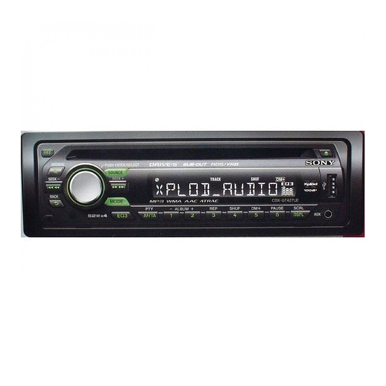
CDX-GT420U/GT424U/GT427UE
(Photo: CDX-GT424U)
SPECIFICATIONS
Harmonic distortion at 1 kHz:
0.5 % (stereo), 0.3 % (mono)
Separation: 35 dB at 1 kHz
Frequency response: 30 – 15,000 Hz
AM
CDX-GT420U: US model:
Tuning range: 530 – 1,710 kHz
Antenna (aerial) terminal:
External antenna (aerial) connector
Intermediate frequency: 10.7 MHz/450 kHz
Sensitivity: 30 μV
FM/MW/LW COMPACT DISC PLAYER
CDX-GT420U: AEP, UK, Russian model/GT424U/GT427UE
FM/MW/SW COMPACT DISC PLAYER
GT470U/GT470US
Russian Model
Model Name Using Similar Mechanism
CD Drive Mechanism Type
Optical Pick-up Name
MW/LW
CDX-GT420U: AEP, UK, Russian model/
GT424U/GT427UE:
Tuning range:
MW: 531 – 1,602 kHz
LW: 153 – 279 kHz
Antenna (aerial) terminal:
External antenna (aerial) connector
Intermediate frequency:
10.7 MHz/450 kHz
Sensitivity:
MW: 30 μV, LW: 40 μV
FM/AM COMPACT DISC PLAYER
US Model
CDX-GT420U
AEP Model
UK Model
CDX-GT420U/GT424U
E Model
CDX-GT470U/GT470US
CDX-GT420U/GT427UE
NEW
MG-101I-188//Q
DAX-25A
– Continued on next page –
CDX-GT420U: US model
CDX-GT470U/GT470US
Advertisement
Table of Contents

Related Manuals for Sony CDX-GT420U


Summary of Contents for Sony CDX-GT420U
- Page 1 SPECIFICATIONS CD Player section Harmonic distortion at 1 kHz: MW/LW 0.5 % (stereo), 0.3 % (mono) CDX-GT420U: AEP, UK, Russian model/ Signal-to-noise ratio: 120 dB Separation: 35 dB at 1 kHz GT424U/GT427UE: Frequency response: 10 – 20,000 Hz Frequency response: 30 – 15,000 Hz Tuning range: Wow and fl...
- Page 2 Audio outputs terminal (sub/rear switchable) Power antenna (aerial) relay control terminal Power amplifi er control terminal Inputs: Telephone ATT control terminal (CDX-GT420U: AEP, UK, Russian model/ GT424U/GT427UE) Remote controller input terminal Antenna (aerial) input terminal AUX input jack (stereo mini jack) Tone controls: Low: ±10 dB at 60 Hz (XPLOD)
- Page 3 COMPONENTS IDENTIFIED BY MARK 0 OR DOTTED LINE WITH MARK 0 ON THE SCHEMATIC DIAGRAMS AND IN THE PARTS LIST ARE CRITICAL TO SAFE OPERATION. REPLACE THESE COMPONENTS WITH SONY PARTS WHOSE PART NUMBERS APPEAR AS SHOWN IN THIS MANUAL OR IN SUPPLEMENTS PUBLISHED BY SONY.
-
Page 4: Table Of Contents
CDX-GT420U/GT424U/GT427UE/GT470U/GT470US This compact disc player is classifi ed as a CLASS 1 LASER TABLE OF CONTENTS product. The CLASS 1 LASER PRODUCT label is located on the exterior. SERVICE NOTE ............. Except GT420U: US model GENERAL Location of Controls ............ -
Page 5: Service Note
CDX-GT420U/GT424U/GT427UE/GT470U/GT470US SECTION 1 SERVICE NOTE EXTENSION CABLE AND SERVICE POSITION NOTE FOR REPLACEMENT OF THE SERVO BOARD When repairing or servicing this set, connect the jig (extension When repairing, the complete SERVO board (A-1362-921-A) cable) as shown below. should be replaced since any parts in the SERVO board cannot be repaired. -
Page 6: General
(BACK) button page 8 To return to the previous display. Receptor for the card remote commander • CDX-GT420U: AEP, UK, Russian model/GT424U/GT427UE Location of controls and basic operations Main unit SEEK –/+ buttons The following buttons on the card remote... -
Page 7: Card Remote Commander
CDX-GT420U/GT424U/GT427UE/GT470U/GT470US Ver. 1.1 • CDX-GT470U/GT470US Location of controls and basic operations Main unit SEEK –/+ buttons The following buttons on the card remote commander have also different buttons/functions CD/USB: from the unit. Remove the insulation film before To skip tracks (press); skip tracks use (page 4). -
Page 8: Connections
CDX-GT420U/GT424U/GT427UE/GT470U/GT470US • CONNECTIONS • CDX-GT420U: US model RCA pin cord (not supplied) AUDIO OUT can be switched SUB or REAR. For details, see the supplied Operating Instructions. Insert with the cord upwards. Cordon à broche RCA (non fourni) AUDIO OUT peut être commuté sur SUB ou REAR. - Page 9 CDX-GT420U/GT424U/GT427UE/GT470U/GT470US • CDX-GT420U: AEP, UK, Russian model/GT424U/GT427UE Note for the antenna (aerial) connecting Hinweis zum Anschließen der Antenne Remarque sur le raccordement de Nota per il collegamento dell’antenna Opmerking bij de antenne-aansluiting If your car antenna (aerial) is an Wenn Ihre Autoantenne der ISO-Norm l’antenne...
- Page 10 CDX-GT420U/GT424U/GT427UE/GT470U/GT470US • CDX-GT470U/GT470US RCA pin cord (not supplied) AUDIO OUT can be switched SUB or REAR. For details, see the supplied Operating Instructions. Insert with the cord upwards. Cable con terminales RCA (no suministrado) AUDIO OUT (Salida de audio) puede...
- Page 11 CDX-GT420U/GT424U/GT427UE/GT470U/GT470US Ver. 1.1 MEMO...
-
Page 12: Disassembly
CDX-GT420U/GT424U/GT427UE/GT470U/GT470US SECTION 3 DISASSEMBLY • This set can be disassembled in the order shown below. 3-1. SUB PANEL ASSY (Page 13) 3-2. CD MECHANISM BLOCK (Page 13) 3-4. SERVO BOARD 3-3. MAIN BOARD (Page 14) (Page 14) 3-5. CHASSIS (T) SUB ASSY (Page 15) 3-6. -
Page 13: Sub Panel Assy
CDX-GT420U/GT424U/GT427UE/GT470U/GT470US Note: Follow the disassembly procedure in the numerical order shown below. 3-1. SUB PANEL ASSY two claws two claws two screws (+PTT 2.6 × 6) sub panel assy 3-2. CD MECHANISM BLOCK bracket (CD) CD mechanism block two screws (+PTT 2.6 ×... -
Page 14: Main Board
CDX-GT420U/GT424U/GT427UE/GT470U/GT470US 3-3. MAIN BOARD two screws (+PTT 2.6 × 8) two screws (+P 2.6 × 8) two screws (+PTT 2.6 × 10) two screws (+BTT 2.6 × 5) screw (+P 2.6 × 10) screw (+PTT 2.6 × 10) heat sink... -
Page 15: Chassis (T) Sub Assy
CDX-GT420U/GT424U/GT427UE/GT470U/GT470US 3-5. CHASSIS (T) SUB ASSY two precision screws two precision screws (+P 1.7 × 2.2) (+P 1.7 × 2.2) chassis (T) sub assy claw 3-6. ROLLER ARM ASSY roller arm assy gear (RA1) spring (RAL) washer spring (RAR) -
Page 16: Chassis (Op) Assy
CDX-GT420U/GT424U/GT427UE/GT470U/GT470US 3-7. CHASSIS (OP) ASSY chassis (OP) assy tension spring (KF) coil spring (damper) (natural) coil spring (damper) (green) slider (R) lever (D) gear (LE1) 3-8. CHUCKING ARM SUB ASSY chucking arm sub assy spring Note: Have this portion receive the chassis. -
Page 17: Sled Motor Assy
CDX-GT420U/GT424U/GT427UE/GT470U/GT470US 3-9. SLED MOTOR ASSY three serration screws (M 2 × 3) sled mtor assy spring turn table spring stand Note: Never remove these parts since they were adjusted. stand Note: Place the stand with care not to touch the turn table. -
Page 18: Optical Pick-Up Section
CDX-GT420U/GT424U/GT427UE/GT470U/GT470US 3-10. OPTICAL PICK-UP SECTION optical pick-up section Note: Be careful not to touch the lens and hologram terminal when removing the optical pick-up section. 3-11. OPTICAL PICK-UP pan tapping screw (M 1.4 × 2.5) leaf spring (sub guide) leaf spring (OP) -
Page 19: Diagnosis Function
CDX-GT420U/GT424U/GT427UE/GT470U/GT470US SECTION 4 DIAGNOSIS FUNCTION Description of the Diagnostics function: 4. Contents of each display mode 4-1. Reset count display mode 1. Setting the Diag display mode With the power off, press the [4] button, [5] button, and [4] button on the set body or the remote control (for more than 2 seconds) in turn. - Page 20 CDX-GT420U/GT424U/GT427UE/GT470U/GT470US 4-5. CD error information display mode 4-6. OFFSET/FAILURE error display mode 4-5-1. Error description Operating hours Error information Error description Error description Indication Description (in hexadecimal (0: OFFSET, 1: FAILURE) SERVO ERROR format) Recency of information LOADING ERROR Recency of information 1-3: 1 represents the latest.
- Page 21 CDX-GT420U/GT424U/GT427UE/GT470U/GT470US Ver. 1.1 4-7-2. Operating hours The display mode is switched by each rotation of [2/ALBM+] or [1/ALBM–] keys during the CD error information display mode. Operating hours USB error info history 1 (latest) Error description plus error details display Recency of information 1-5: 1 represents the latest.
- Page 22 CDX-GT420U/GT424U/GT427UE/GT470U/GT470US MEMO...
-
Page 23: Diagrams
CDX-GT420U/GT424U/GT427UE/GT470U/GT470US SECTION 5 DIAGRAMS 5-1. BLOCK DIAGRAM – MAIN Section – ELECTRONIC VOLUME IC401 OUT–RL AUX-RCH J901 OUT–RR R-CH 9 AUX-LCH (REAR) AUX-RCH 7 AUX-RCH OUT–FL OUT–FR R-CH (FRONT) (FRONT) J652 SUBOUT–L AUDIO OUT I2C BUS CONTROLLED POWER AMP/ SUBOUT–R... -
Page 24: Block Diagram -Display Section
CDX-GT420U/GT424U/GT427UE/GT470U/GT470US Ver. 1.1 5-2. BLOCK DIAGRAM – DISPLAY Section – SYSTEM CONTROL LCD DRIVE IC501 (2/2) IC901 KEYIN0 KEY MATRIX LCD901 LSW907–917, LIQUID CRYSTAL S901–906 DISPLAY PANEL KEYIN1 92 KEYACK1 RE901 PUSH ENTER/ SELECT LCD DATA PANEL+B PANEL+B (VOLUME) LCD CLK... - Page 25 CDX-GT420U/GT424U/GT427UE/GT470U/GT470US Ver. 1.1 THIS NOTE IS COMMON FOR PRINTED WIRING BOARDS AND SCHEMATIC DIAGRAMS. • Waveforms – MAIN Board – (In addition to this, the necessary note is printed in each block.) For Printed Wiring Boards. For Schematic Diagrams. IC501...
-
Page 26: Printed Wiring Board -Main Section
CDX-GT420U/GT424U/GT427UE/GT470U/GT470US Ver. 1.1 5-3. PRINTED WIRING BOARD – MAIN Section – • : Uses unleaded solder. J652 (ANTENNA) J370 (REMOTE IN) US,E,EA,IND,MX MODEL CN300 L370 C330 C432 C452 C325 JW59 Q605 R603 JW50 JW60 R449 D602 F901 C444 C424 C304... -
Page 27: Schematic Diagram -Main Section (1/3)
CDX-GT420U/GT424U/GT427UE/GT470U/GT470US Ver. 1.1 5-4. SCHEMATIC DIAGRAM – MAIN Section (1/3) – • See page 32 for IC Block Diagram. C303 C444 C424 L902 C306 C308 C325 C330 L901 JC31 C301 C304 C305 C307 JC29 JC30 C309 C317 IC300 R303 C319... -
Page 28: Schematic Diagram -Main Section (2/3)
CDX-GT420U/GT424U/GT427UE/GT470U/GT470US Ver. 1.1 5-5. SCHEMATIC DIAGRAM – MAIN Section (2/3) – • See page 25 for waveform. • See page 32 for IC Block Diagrams. J652 C452 C432 C445 C443 Q420 Q440 Q452 Q432 C426 C423 R448 R447 JC491 C999... -
Page 29: Schematic Diagram -Main Section (3/3)
CDX-GT420U/GT424U/GT427UE/GT470U/GT470US Ver. 1.1 5-6. SCHEMATIC DIAGRAM – MAIN Section (3/3) – • See page 25 for Waveforms. • See page 33 for IC Block Diagrams. • See page 34 for IC Pin Function Description of IC501. (Page 27) R370 J370... -
Page 30: Printed Wiring Boards -Key Section
CDX-GT420U/GT424U/GT427UE/GT470U/GT470US 5-7. PRINTED WIRING BOARDS – KEY Section – • : Uses unleaded solder. • Semiconductor Location LED941, LED942 LED942, LED944, S901 Ref. No. Location S902 S903 S902 LED931 D804 (LCD BACK LIGHT) D903 H-10 R902 D908 H-11 LED951 D909... -
Page 31: Schematic Diagram -Key Section
CDX-GT420U/GT424U/GT427UE/GT470U/GT470US 5-8. SCHEMATIC DIAGRAM – KEY Section – R981 R974 LED943 LSW915(2/2) R943 R947 LED951 R982 R975 LED931 LED941 LSW913(2/2) LSW917(2/2) R945 IC971 LED946 LSW914(2/2) R944 R948 LED952 C971 LED944 LSW912(2/2) R941 R953 R931 LSW908(2/2) LSW909(2/2) R932 R955 R951 LED953... - Page 32 CDX-GT420U/GT424U/GT427UE/GT470U/GT470US Ver. 1.1 • IC Block Diagrams IC50 TDA7333013TR (AEP, UK, RU) (MAIN Board (2/3)) IC300 TDA8588AJ/N2/R1/M5 (GT420U: AEP, UK, RU/GT424U) (MAIN Board (1/3)) BAND PASS SINC4 SIGMA DELTA INTERPOLATOR IC300 TDA8588AJ/N2/R1 FILTER FILTER CONVERTER VDDA (GT420U: US/GT427UE/GT470U/GT470US) (MAIN Board (1/3))
- Page 33 CDX-GT420U/GT424U/GT427UE/GT470U/GT470US IC803 TPS40200DRG4 (MAIN Board (3/3)) UVLO ISNS LOGIC DRIVER E/A AND SS REFFERENCE SOFT-START 700mV OVERCURRENT COMP ENABLE E/A IC804 TPS2051BDRG4 (MAIN Board (3/3)) CHARGE PUMP CURRENT DRIVER LIMIT UVLO THERMAL SENCE IC805 TC7WH123FU(TE12R) (MAIN Board (3/3)) RX/CX...
- Page 34 CDX-GT420U/GT424U/GT427UE/GT470U/GT470US Ver. 1.1 • IC Pin Function Description MAIN BOARD IC501 M3062LFGP-050FP (SYSTEM CONTROL) (EXCEPT GT427UE) MAIN BOARD IC501 M3062LFGP-053FP (SYSTEM CONTROL) (GT427UE) Pin No. Pin Name Description LCD DATA Liquid crystal display panel serial data signal output LCD CLK Liquid crystal display panel serial clock signal output Not used.
- Page 35 CDX-GT420U/GT424U/GT427UE/GT470U/GT470US Pin No. Pin Name Description ILLUMI SEL Illumination voltage setting signal input for panel “H”: 10.4V, “L”: 9V 66 to 68 Not used. (Open) B OUTSEL Black out setting signal input “H”: Block out AREASEL 2 Destination setting pin 2...
-
Page 36: Exploded Views
CDX-GT420U/GT424U/GT427UE/GT470U/GT470US Ver. 1.1 SECTION 6 EXPLODED VIEWS Note: • -XX and -X mean standardized parts, so • The mechanical parts with no reference The components identifi ed by mark 0 they may have some difference from the number in the exploded views are not sup- or dotted line with mark 0 are critical for original one. -
Page 37: Front Panel Section
BUTTON ASSY (S) (GT420U:US/GT470U) X-2187-544-1 CASE ASSY (for FRONT PANEL) (EXCEPT US) X-2176-322-1 CAP (USB) ASSY CN902 1-820-877-11 CONNECTOR, USB (SOCKET) (USB) 3-251-320-01 EMBLEM (NO. 2.5), SONY LCD901 1-802-569-11 DISPLAY PANEL, LIQUID CRYSTAL X-2186-948-1 KNOB (VOL) (SV) ASSY RE901 1-479-902-21 ENCODER, ROTARY... -
Page 38: Cd Mechanism Section (Mg-101I-188//Q)
CDX-GT420U/GT424U/GT427UE/GT470U/GT470US 6-3. CD MECHANISM SECTION (MG-101I-188//Q) not supplied not supplied not supplied not supplied not supplied not supplied not supplied not supplied not supplied not supplied not supplied not supplied Ref. No. Part No. Description Remark Ref. No. Part No. -
Page 39: Electrical Parts List
CDX-GT420U/GT424U/GT427UE/GT470U/GT470US Ver. 1.1 SECTION 7 JACK ELECTRICAL PARTS LIST Note: • Due to standardization, replacements in • RESISTORS When indicating parts by reference num- the parts list may be different from the All resistors are in ohms. ber, please include the board name. - Page 40 CDX-GT420U/GT424U/GT427UE/GT470U/GT470US Ver. 1.1 Ref. No. Part No. Description Remark Ref. No. Part No. Description Remark < SWITCH > R911 1-216-821-11 METAL CHIP 1/10W R912 1-216-822-11 METAL CHIP 1.2K 1/10W LSW907 1-786-805-13 SWITCH, TACTILE (WITH LED) R913 1-216-823-11 METAL CHIP 1.5K 1/10W (M >...
- Page 41 CDX-GT420U/GT424U/GT427UE/GT470U/GT470US Ver. 1.1 MAIN Ref. No. Part No. Description Remark Ref. No. Part No. Description Remark R954 1-216-811-11 METAL CHIP 1/10W 1-126-947-11 ELECT 47uF (EXCEPT GT427UE) 1-162-970-11 CERAMIC CHIP 0.01uF R955 1-216-811-11 METAL CHIP 1/10W 1-126-947-11 ELECT 47uF (GT427UE) 1-162-970-11 CERAMIC CHIP 0.01uF...
- Page 42 CDX-GT420U/GT424U/GT427UE/GT470U/GT470US Ver. 1.1 MAIN Ref. No. Part No. Description Remark Ref. No. Part No. Description Remark C401 1-124-234-00 ELECT 22uF C702 1-164-005-11 CERAMIC CHIP 0.47uF C402 1-162-970-11 CERAMIC CHIP 0.01uF C703 1-164-005-11 CERAMIC CHIP 0.47uF C403 1-124-584-00 ELECT 100uF C704 1-115-340-11 CERAMIC CHIP 0.22uF...
- Page 43 CDX-GT420U/GT424U/GT427UE/GT470U/GT470US Ver. 1.1 MAIN Ref. No. Part No. Description Remark Ref. No. Part No. Description Remark D304 6-501-362-01 DIODE 1A4-TA26 JC502 1-216-296-11 SHORT CHIP D305 6-501-362-01 DIODE 1A4-TA26 JC503 1-216-296-11 SHORT CHIP D306 6-501-362-01 DIODE 1A4-TA26 JC504 1-216-296-11 SHORT CHIP...
- Page 44 CDX-GT420U/GT424U/GT427UE/GT470U/GT470US Ver. 1.1 MAIN Ref. No. Part No. Description Remark Ref. No. Part No. Description Remark < RESISTOR > R472 1-216-833-11 METAL CHIP 1/10W R473 1-216-864-11 SHORT CHIP 1-216-809-11 METAL CHIP 1/10W R485 1-218-883-11 METAL CHIP 0.5% 1/10W (AEP,UK,RU) R491...
- Page 45 CDX-GT420U/GT424U/GT427UE/GT470U/GT470US Ver. 1.1 MAIN SERVO Ref. No. Part No. Description Remark Ref. No. Part No. Description Remark R562 1-216-845-11 METAL CHIP 100K 1/10W S501 1-571-478-11 SWITCH, SLIDE (FREQUENCY SELECTOR) R564 1-216-845-11 METAL CHIP 100K 1/10W (E,IND,MX) R565 1-216-845-11 METAL CHIP...
- Page 46 CDX-GT420U/GT424U/GT427UE/GT470U/GT470US Ver. 1.1 Ref. No. Part No. Description Remark PARTS FOR INSTALLATION AND CONNECTIONS ************************************** X-2179-431-1 FRAME ASSY, FITTING 2-686-803-11 COLLAR 3-255-785-02 COLLAR (1DIN) (for Maruti Suzuki) 3-246-471-01 KEY (FRAME) X-3381-154-1 SCREW ASSY (BS4), FITTING (GT470U/GT470US) X-3382-926-1 SCREW ASSY (BS), FITTING (AEP,UK,RU)
- Page 47 CDX-GT420U/GT424U/GT427UE/GT470U/GT470US MEMO...
- Page 48 CDX-GT420U/GT424U/GT427UE/GT470U/GT470US REVISION HISTORY Checking the version allows you to jump to the revised page. Also, clicking the version at the top of the revised page allows you to jump to the next revised page. Ver. Date Description of Revision 2007.11 Maruti Suzuki model addition of CDX-GT470US (Indian Model).