Invacare TRACER EX2 User Manual
Invacare wheelchair user manual
Hide thumbs
Also See for TRACER EX2:
- Owner's operator and maintenance manual (56 pages) ,
- Information (2 pages) ,
- Operator and maintenance manual (44 pages)

Related Manuals for Invacare TRACER EX2


Summary of Contents for Invacare TRACER EX2
-
Page 1: User Manual
User Manual ® Invacare Tracer™ EX2 Wheelchair This manual MUST be given to the user of the product. BEFORE using this product, read this manual and save for future reference. - Page 2 © 2011 Invacare Corporation. All rights reserved. Republication, duplication or modification in whole or in part is prohibited without prior written permission from Invacare. Trademarks are identified by ™ and ®. All trademarks are owned by or licensed to Invacare Corporation or its subsidiaries unless otherwise noted.
-
Page 3: Table Of Contents
Adjusting Armrest Height ... 39 Removing/Installing Armrests... 40 SEAT AND BACK Replacing Back Upholstery ... 41 Replacing Seat Upholstery ... 41 Adjusting the Seat Width ... 42 REAR WHEELS Removing/Installing Rear Wheels... 46 Part No 1110546 Invacare CONTENTS ® Tracer™ EX2 Wheelchair... - Page 4 11 SEAT-TO-FLOOR Changing Seat-to-Floor Height ... 57 12 OPTIONS Installing Amputee Bracket... 59 Installing Crutch and Cane Carrier... 61 Installing the Seat Positioning Strap ... 62 Installing the Wheel Lock Extension Handle... 63 ® Invacare Tracer™ EX2 Wheelchair Part No 1110546...
-
Page 5: General
Caution indicates a potentially hazardous situation which, if not avoided, may result in property damage or minor injury or both. IMPORTANT Indicates a hazardous situation that could result in damage to property if it is not avoided. Gives useful tips, recommendations and information for efficient, trouble-free use. Part No 1110546 Invacare 1 GENERAL ® Tracer™ EX2 Wheelchair... -
Page 6: Limited Warranty
Invacare warrants the side frames and cross members of this product when purchased new and unused to be free from defects in materials and workmanship for a period of five (5) years from the date of purchase from Invacare or a dealer, with a copy of the seller’s invoice required for coverage under this warranty. -
Page 7: Overview
No. 1091554 WARNING Do not operate without the anti- tip tubes installed. AVERTISSEMENT NE PAS utiliser sans d’abord avoir installé les antibascules. No. 1091552 ® Invacare Tracer™ EX2 Wheelchair 2 OVERVIEW Crossmember Lower Frame Tube... -
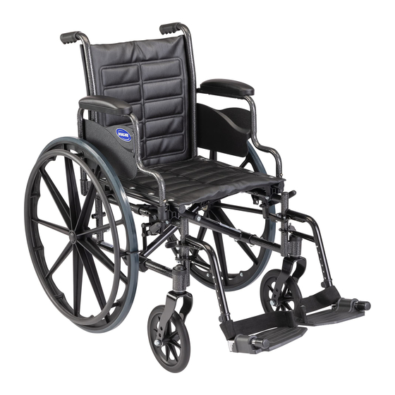
Page 8: Component Identification
2 OVERVIEW Component Identification Rear Wheel Handrim Rear Wheel Axle ® Invacare Tracer™ EX2 Wheelchair Back Upholstery Front Caster Wheel Lock Seat Upholstery Wheelchair Frame Part No 1110546... -
Page 9: Typical Product Parameters
Hemi: (SA Frame) Back Style Back Height Arm Styles Front Riggings Rear Axle Rear Wheels Handrims Part No 1110546 Tracer EX2 , 25 , 27 , 26 , 28 inches 16, 18, or 20 inches 16 inches 16 inches inches... - Page 10 * - These options are standard for this model. ** - The seat-to-floor heights are based on urethane tires. These heights can vary +/- *** - Weights based on 18-inch wide wheelchair without front riggings. Weights will vary depending on how the wheelchair is equipped. ®...
-
Page 11: Safety
NOTICE THE INFORMATION CONTAINED IN THIS DOCUMENT IS SUBJECT TO CHANGE WITHOUT NOTICE. Check all parts for shipping damage and test before using. In case of damage, DO NOT use. Contact Invacare/Carrier for further instruction. Part No 1110546 Invacare 3 SAFETY ®... - Page 12 If so equipped, anti-tippers MUST be attached at all times. Inasmuch as the anti-tippers are an option for 0° or 3° on this wheelchair (You may order with or without the anti-tippers), Invacare strongly recommends ordering the anti-tippers as a safeguard for the wheelchair user.
-
Page 13: General Warnings
DO NOT stand on the frame of the wheelchair. DO NOT use the footplate as a platform. When getting in or out of the wheelchair, make sure that the footplates are in the upward position. ALWAYS use the handrims for self-propulsion. Inasmuch as the handrims are an option on this wheelchair (you may order with or without the handrims), Invacare strongly recommends ordering the handrims as an additional safeguard for the wheelchair user. - Page 14 Information for Healthcare Professionals/Assistants WARNING When assistance to the wheelchair user is required, remember to use good body mechanics. Keep your back straight and bend your knees whenever tipping the wheelchair or traversing curbs, or other impediments. When learning a new assistance technique, have an experienced assistant help you before attempting it alone.
- Page 15 ALWAYS wear your seat positioning strap. Inasmuch as the seat positioning strap is an option on this wheelchair (you may order with or without the seat positioning strap), Invacare strongly recommends ordering the seat positioning strap as an additional safeguard for the wheelchair user. The seat positioning strap is a positioning strap only. It is not designed for use as a safety device withstanding high stress loads such as auto or aircraft safety belts.
-
Page 16: Weight Limitation
The seat depth, size/position of the front casters, size/position of the rear wheels, use of anti-tipper model, as well as the user condition directly relate to the stability of the wheelchair. Any change to one or any combination of the seven may cause the wheelchair to decrease in stability. -
Page 17: Weight Training
WARNING Invacare does not recommend the use of its wheelchairs as a weight training apparatus. Invacare wheelchairs have not been designed or tested as a seat for any kind of weight training. If occupant uses said wheelchair as a weight training apparatus, Invacare shall not be liable for bodily injury or damage to the wheelchair and the warranty is void. -
Page 18: Safety/Handling Of Wheelchairs
Use this information only as a basic guide. The techniques that are discussed on the following pages have been used successfully by many. Individual wheelchair users often develop skills to deal with daily living activities that may differ from those described in this manual. Invacare recognizes and encourages each individual to try what works best for him/her in overcoming architectural obstacles that they may encounter. - Page 19 DO NOT lean forward out of the wheelchair any further than the length of the armrests. Make sure the casters are pointing in the forward position whenever you lean forward. This can be achieved by advancing the wheelchair and then reversing it in a straight line.
- Page 20 When tipping the wheelchair, an assistant should grasp the back of the wheelchair on a non-removable (non-detachable) part. Inform the wheelchair occupant before tipping the wheelchair and remind him/her to lean back. Be sure the occupant’s feet and hands are clear of all wheels and/or pinch points.
- Page 21 The second assistant (positioned in the front of the wheelchair), with a firm hold on a non-detachable part of the framework, lifts the wheelchair up and on to the next stair above and steadies the wheelchair as the assistant behind the wheelchair places one foot on the next stair above and repeats process.
- Page 22 WARNING Before attempting to transfer in or out of the wheelchair, every precaution should be taken to reduce the gap distance. Turn both casters parallel to the object you are transferring onto. Also be certain the wheel locks are engaged to help prevent the wheels from moving.
- Page 23 DO NOT place hand or fingers on the underside of the seat frame rail when opening or closing the wheelchair. DO NOT sit or transfer into the wheelchair unless it is fully open and the seat frame rails are fully seated into the side frame H-blocks.
- Page 24 Point your fingers and thumb to the inside of the wheelchair. Press downward on the top of the seat rail until the wheelchair is fully open and the seat rails are fully seated in the H-blocks.
-
Page 25: Safety Inspection/Troubleshooting
Regular cleaning will reveal loose or worn parts and enhance the smooth operation of your wheelchair. To operate properly and safely, your wheelchair MUST be cared for just like any other vehicle. Routine maintenance will extend the life and efficiency of your wheelchair. - Page 26 ❑ Check that all labels are present and legible. Replace if necessary. Inspect/Adjust Weekly ❑ Ensure that the wheel locks prevent the wheelchair from moving when engaged. ❑ Inspect tires for flat spots and wear. ❑ Check pneumatic tires for proper inflation.
- Page 27 ❑ Ensure that casters are free of debris. Inspect/Adjust Monthly ❑ Ensure that the wheelchair rolls straight (no excessive drag or pull to one side). ❑ Check that the wheel locks DO NOT interfere with tires when rolling. ❑ Check that the wheel lock pivot points are free of wear and looseness.
-
Page 28: Troubleshooting
Check that all labels are present and legible. Replace if necessary. Troubleshooting Chair Chair 3 Sluggish Turn or Veers Wheels Performance Right/Left ® Invacare Tracer™ EX2 Wheelchair Casters Squeaks and Flutter Rattles Looseness in Solutions Chair Check tires for correct and equal pressure Check for loose nuts and bolts. -
Page 29: Maintenance
DO NOT overtighten hardware attaching to the frame. This could cause damage to the frame tubing. Suggested Maintenance Procedures Before using your wheelchair, make sure all nuts and bolts are tight. Check all parts for damage or wear and replace. - Page 30 10. Hand grips should be checked monthly for wear/looseness/deterioration. Clean if desired. Replace if looseness or deterioration is found Replacing/Repairing Rear Wheel Tire/Tube WARNING Replacement of solid urethane tires is not recommended. If the solid urethane tire needs repaired, Invacare recommends replacing the complete wheel assembly. Replacing/Repairing Caster Tire/Tube WARNING Replacement of solid rubber tires is not recommended.
-
Page 31: Front Riggings
Installing Turn the front rigging assembly to the side. Install the hinge plates on the front rigging assembly onto the hinge pins on the wheelchair frame. When performing STEP 3, it may be necessary to pull release lever toward front of chair to assist the front rigging to lock in place. - Page 32 5 FRONT RIGGINGS ® Invacare Tracer™ EX2 Wheelchair Front Rigging Release Lever Hinge Pins Hinge Plates Swingaway footrest shown FIGURE 1 Installing/Removing Front Riggings Front Rigging Assembly Footplate Part No 1110546...
-
Page 33: Adjusting Footplate Height
Removing Front Riggings on page 31. Part No 1110546 Adjustment Holes Cam Lock Lever Swingaway footrest shown FIGURE 2 Adjusting Footplate Height - Spring Button Invacare 5 FRONT RIGGINGS Front Rigging Support Release Button Footplate Assembly ® Tracer™ EX2 Wheelchair... - Page 34 Front Rigging Support Swingaway Adjustment footrest shown Hole Button Head Cam Lock Lever Inside of Swingaway Front Rigging ® Invacare Tracer™ EX2 Wheelchair Front Rigging Support Button Head Screw Screw Threaded Rivet FIGURE 3 Adjusting Footplate Height - Bolt-In-Place Adjustment Hole Footplate...
-
Page 35: Raising/Lowering Elevating Legrest Assembly
Otherwise injury may occur due to pinch points. The wheelchair user’s leg MUST be supported by an assistant before attempting to lower legrest. To raise the elevating legrest, the assistant should hold the support tube and raise the elevating legrest until the desired height is obtained. -
Page 36: Installing Impact Guards/Calf Strap
Ensure the upper portion of the impact guard is between the two horizontal supports of the footrest. Secure one side of the calf strap around each footrest (with the impact guards attached, if present). ® Invacare Tracer™ EX2 Wheelchair Calf Strap... -
Page 37: Replacing Heel Loop
Using a screwdriver to hold the threaded rivet in position, securely tighten the button head screw. Torque to 32 in-lbs. Rotate cam lock lever down to locked position. Part No 1110546 Invacare 5 FRONT RIGGINGS ® Tracer™ EX2 Wheelchair... - Page 38 5 FRONT RIGGINGS DETAIL “A” Footplates with Spring Buttons Front Rigging Support Release Button Footplate Assembly Adjustment Holes Cam Lock Lever Mounting ® Invacare Tracer™ EX2 Wheelchair DETAIL “B” Bolt-in-Place Footplates Front Rigging Support Inside of Swingaway Front Rigging Footplate Assembly...
-
Page 39: Arms
Adjusting Armrest Height WARNING Make sure the height adjustment lever is in the locked position before using the wheelchair. Unlock the armrest by flipping the height adjustment lever on the top front of the armrest to the up (horizontal) position. -
Page 40: Removing/Installing Armrests
6 ARMS Removing/Installing Armrests WARNING Make sure the height adjustment lever is in the locked position before using the wheelchair. Removing Armrest Push down on armrest to ensure it is fully seated in front and rear sockets. STEP 1 prevents the release buttons from hanging up on the sockets during removal. -
Page 41: Seat And Back
Install new seat upholstery by reversing STEPS 1-2. Part No 1110546 Washers Mounting Screws FIGURE 1 Replacing Back Upholstery Mounting Screw FIGURE 2 Replacing Seat Upholstery Invacare 7 SEAT AND BACK Back Upholstery Washers 16-inch Seat Depth Seat Upholstery Wheelchair Frame ®... -
Page 42: Adjusting The Seat Width
Remove the four button screws and locknuts that secure the two pivot links to the wheelchair frame and crossbraces. Remove the two button screws, locknuts and crossbrace saddle that secures the bottom of the crossbrace to the wheelchair frame. Repeat for other crossbrace. - Page 43 Button Screw Crossbrace (STEPS 2,7) Saddle (STEPS 3,8) Locknut Crossbrace Saddle Wheelchair (STEPS 3,8) (STEPS 3,8) Frame See Detail “B” See Detail “A” FIGURE 4 Adjusting the Seat Width - Swingaway Front Riggings ® Part No 1110546 Invacare Tracer™ EX2 Wheelchair...
- Page 44 Coved Washer Locknut Washer DETAIL “A” Crossbraces Coved Wheelchair Frame Washers Hex Screw DETAIL “B” - CROSSBRACE Washer HARDWARE (STEPS 4,5) Crossbrace Saddle FIGURE 5 Adjusting the Seat Width - Swingaway Front Riggings ® Invacare Tracer™ EX2 Wheelchair Part No 1110546...
-
Page 45: Fixed Frame
Remove the hex screw and locknut that secure the two existing crossbraces together. Removing Upper Mounting Hardware While pushing down on the rear seat guide, pull up the front seat guide until the front seat guide releases from the wheelchair frame. Pull the crossbrace away from the rear seat guide. -
Page 46: Rear Wheels
If changing the size of the rear wheel or a change in the seat-to-floor height is desired, this procedure MUST be performed by a qualified technician. Make sure both rear wheels are the same size and are installed into the same respective mounting hole before using the wheelchair, otherwise injury may occur. ® Invacare Tracer™ EX2 Wheelchair Part No 1110546... -
Page 47: Replacing/Repairing Rear Wheel Tire
This procedure MUST be performed by a qualified technician. If replacing the same size rear wheel, note the mounting position on the wheelchair frame for proper reinstallation of the new rear wheel. Remove the dust cap (SA Frame only), hex screw, washer (SA Frame only), spacer (if installed) and locknut that secure the rear wheel to the wheelchair frame. -
Page 48: Replacing Rear Wheel Handrim
If the wheelchair is equipped with permanent axles, this procedure MUST be performed by a qualified technician. Remove the rear wheel from the wheelchair. Refer to Removing/ Installing Rear Wheels on page 46. Remove the mounting screws that secure the handrim to rear wheel. -
Page 49: Front Casters
Installing/Replacing Front Casters/Forks WARNING Make sure both fork/caster assemblies are the same size before using the wheelchair, otherwise injury may occur. This procedure can be performed if replacing the exact same size front caster. -
Page 50: Adjusting Forks
WARNING Make sure both front casters are the same size and are installed into the same respective mounting hole before using the wheelchair, otherwise injury may occur. Note the mounting position on the fork assembly for proper reinstallation of the new front caster. -
Page 51: Anti-Tippers/Wheel Locks
If so equipped, anti-tippers MUST be attached at all times. Inasmuch as the anti-tippers are an option for 0° or 3° on this wheelchair (You may order with or without the anti-tippers), Invacare strongly recommends ordering the anti-tippers as a safeguard for the wheelchair user. - Page 52 Ensure that the release button of the anti-tipper fully protrudes out of the hole in the bottom of the wheelchair frame tubing. Place the wheelchair on a flat surface. Measure the distance between the bottom of the anti-tipper wheels and the ground/floor.
- Page 53 2 inches. If the 1 to 2 inch distance cannot be achieved, a different model may be required. Contact an Invacare dealer or qualified technician. Part No 1110546 10 ANTI-TIPPERS/WHEEL LOCKS to 2 inches, adjust anti-tippers. Refer to Adjusting the FIGURE 3...
-
Page 54: Using/Adjusting Patient Operated Wheel Locks
DO NOT attempt to stop a moving wheelchair with wheel locks. Wheel locks are not brakes. If the wheelchair is equipped with push to lock wheel locks, elevating legrests, and wheel lock extension handles, the wheel lock extension handles MUST be removed before swinging the elevating legrests to the side, otherwise injury or damage may result. -
Page 55: Adjusting Patient Operated Wheel Locks
DO NOT attempt to stop a moving wheelchair with wheel locks. Wheel locks are not brakes. If wheel locks do not hold the occupied wheelchair in place, contact a qualified technician; otherwise injury or damage may occur. If wheels are pneumatic, before adjusting the wheel lock assemblies, ensure that the tires are inflated to the recommended ... - Page 56 10 ANTI-TIPPERS/WHEEL LOCKS Bolt and Locknut Mounting Positions Rear Wheel ® Invacare Tracer™ EX2 Wheelchair Wheel Lock DETAIL “A” Handle Wheel Lock Wheel Lock Shoe FIGURE 5 Using Patient Operated Wheel Locks inch ( inch pneumatic tires) Wheel Lock...
-
Page 57: Seat-To-Floor
After any adjustments, repair or service and before use, make sure all attaching hardware is tightened securely - otherwise injury or damage may occur. The seat-to-floor height is not adjustable for the Tracer EX2 wheelchair with the fixed frame option (FF). This procedure applies to the EX2 wheelchair model with swingaway footrests only. 11.1 Changing Seat-to-Floor Height... - Page 58 (IN INCHES) 17½ 19½ DETAIL “A” - REAR WHEEL MOUNTING POSITIONS - ADULT/HEMI FRAME STYLE Bottom ® Invacare Tracer™ EX2 Wheelchair 8-INCH FRONT CASTERS FRONT CASTER REAR WHEEL SIZE MOUNTING POSITION Bottom DETAIL “B” - 8 INCH FORK MOUNTING POSITIONS FIGURE 1 Changing Seat-to-Floor Height...
-
Page 59: Options
* - “A” and "B" are stamped on the sides of the amputee bracket. Install the amputee bracket on the wheelchair frame to the position determined in STEP 1. Make sure the axle spacer is pointing towards the outside of the wheelchair. - Page 60 Left Adult Right Adult Left Axle Spacer Toward Axle Spacer Toward Outside of Wheelchair Outside of Wheelchair Rear View of Amputee Bracket Hex Screws Hemi Left Hemi Right FIGURE 1 Installing Amputee Bracket ® Invacare Tracer™ EX2 Wheelchair Part No 1110546...
-
Page 61: Installing Crutch And Cane Carrier
NEVER insert or remove items while wheelchair is moving. Slide the clamp with the base attached over the end of the step tube of the wheelchair. Ensure the base is towards the inside of the wheelchair. Position the base parallel to the step tube. -
Page 62: Installing The Seat Positioning Strap
ALWAYS wear your positioning strap. Inasmuch as the Seat Positioning Strap is an option on this wheelchair (You may order with or without the seat restraint), Invacare strongly recommends ordering the Seat Positioning Strap as an additional safeguard for the wheelchair user. -
Page 63: Installing The Wheel Lock Extension Handle
12.4 Installing the Wheel Lock Extension Handle WARNING If the wheelchair is equipped with push to lock wheel locks, elevating legrests, and wheel lock extension handles, the wheel lock extension handles MUST be removed before swinging the elevating legrests to the side, otherwise injury or damage may result. - Page 64 Invacare Corporation One Invacare Way Elyria, Ohio USA 44036-2125 800-333-6900 www.invacare.com Rev G - 2/11 Canada 570 Matheson Blvd E Unit Mississauga Ontario L4Z 4G4 Canada 800-668-5324...