GE WSLS1500J Service Manual
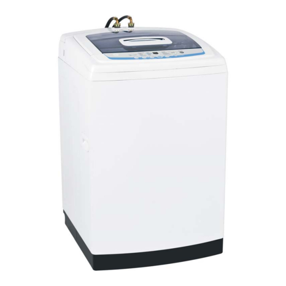
Compact 24" washer
Hide thumbs
Also See for WSLS1500J:
- Owner's manual & installation instructions (72 pages) ,
- Dimensions and installation information (3 pages) ,
- Owner's manual & installation instructions (72 pages)
Table of Contents
Advertisement
Advertisement
Table of Contents

Related Manuals for GE WSLS1500J


Summary of Contents for GE WSLS1500J
- Page 1 Compact 24” Washer WSLS1500J WSLP1500J...
- Page 2 IMPORTANT SAFETY NOTICE The information in this presentation is intended for use by individuals possessing adequate backgrounds of electrical, electronic, & mechanical experience. Any attempt to repair a major appliance may result in personal injury & property damage. The manufacturer or seller cannot be responsible for the interpretation of this information, nor can it assume any liability in connection with its use.
- Page 3 GE Factory Service Employees are required to use safety glasses with side shields, cut resistant (Dyneema®) gloves & steel toe shoes for all repairs. Plano Safety Glasses Steel Toe Shoes Dyneema® Cut Resistant Glove Prescription Safety Glasses Safety Glasses must be compliant with ANSI Z87.1-2003...
-
Page 4: Warranty
Warranty Copyright 2009... - Page 5 Nomenclature W S L S 1 5 0 0 J Product W= Washer Engineering Model Revision S = Space maker Basket Size L = Large Product Type S = Stationary P = Portable Copyright 2009...
-
Page 6: Features And Specs
Features and Specs • 3.1 cubic feet Extra Large • 14 wash cycles • Stainless steel basket • Approximate Shipping Weight 117 lb • Net Weight 106 lb • Overall Depth 26 in • Overall Height 37 1/2 in • Overall Width 23 5/8 in •... - Page 7 Nomenclature Model number in two locations on the back of the machine. Copyright 2009...
- Page 8 Copyright 2009...
-
Page 9: Leveling Washer
Leveling Washer Check to ensure the washer is level. With the door open, the spin basket should be centered in the opening as shown in the “leveled” view. Copyright 2009... - Page 10 Leveling Washer Pull lock lever out and level front of machine Push lever back in to secure setting Close up view Remove 2 screws to replace leg assembly (1 on other side not pictured) Copyright 2009...
-
Page 11: Installation
Installation Copyright 2009... - Page 12 Installed with Dryer DSDR24F Rack Copyright 2009...
- Page 13 WSLP1500 - Portable Connections Checklist • The washer is plugged in. • The water faucets are turned on. • The unit is level. • There are no leaks at the faucet, drain line or washer. Copyright 2009...
-
Page 14: Control Features
Control- Features The control can add an additional 5 rinse cycles. Rinse Cycles Customer makes normal selections and presses the START pad. Any time after that if the customer presses the “OPTIONS” pad the display will show a 1. Pressing the “OPTIONS” pad again will change to 2. The customer can scroll up to 5 rinse cycles. - Page 15 Control- Features Spin The control can add or subtract spin time by scrolling through the OPTIONS pad after the Spin cycle has been initiated. Cycle The increments are smaller and the logic is different. Customer can increase spin time up to 16 minutes, and decrease down to 5. Copyright 2009...
- Page 16 Control- Features Maximizes detergent efficiency by adding water in steps and slowly diluting ULTRA the detergent to the standard level. CLEAN The machine partially fills, (appx 75%) then begins to agitate for approximately 30 seconds. Pauses and continues fill for about 10 seconds, then agitates. It repeats this process, in varying degrees and stages, 4 times before the tub is at the correct water level and the machine completes the wash cycle.
- Page 17 Control- Features CONTROL Only locks the control “during” a cycle. Does not lock the control in the standby mode. LOCK Press and hold “LOAD” and “OPTIONS” pads simultaneously for 3 seconds while machine is in a cycle. Display alternates between CL and time remaining.
- Page 18 Control- Features When the control is first powered on, it defaults to “LOAD SENSING” LOAD SENSING fill. (No “LOAD” size LED lights are lit at this time) The customer can change any of the TEMP, OPTIONS, or CYCLES selection and load sensing remains active.
-
Page 19: Load Sensing
Load Sensing Weight Recognition Function (Load sensing) • The weight recognition function measures the washing load before water is supplied. • The weight recognition function is canceled when water level key is pressed prior to the completion of weight recognition function. •... - Page 20 Control- Features CUSTOM Set the “CYCLES” selection to “CUSTOM CYCLE.” Select “TEMP” and “OPTIONS” choices. CYCLE Press “START” pad. Control remembers and the next time those setting will be displayed. CUSTOM CYCLE always utilizes “Load Sensing” Consumer can not Note: lock in a load size.
- Page 21 Control - Removal Remove two plugs and screws Copyright 2009...
- Page 22 Control - Removal • Pry out small rubber plugs • Slide Control Panel to the left to release. • Remove Phillips-head screws • Lift up from rear to release front clips • Note mini manual location Copyright 2009...
- Page 23 Control - Removal Remove 5 Phillips head screws that secure the PCB to the control panel Copyright 2009...
- Page 24 Control - Removal Caution: • To prevent misalignment of the control panel selector buttons to the PCB, when installing the PCB to the control panel, route the wiring utilizing the wire tabs • Make sure all screw locations on the PCB fully contact the control panel before installing the screws.
- Page 25 Control – Pin Locations CN1 - Door switch, Unbalance switch, Pressure sensor CN2 - Line Voltage CN3 - Neutral, Neutral to Water valve solenoids CN4 - Washing motor CN5 - Washing motor, Washing motor condenser CN6 - Water valve solenoids, Brake control motor, Drain pump motor Copyright 2009...
- Page 26 Control – Wire Positions Note the schematic drawing and the actual wire locations on the 11 pin CN1 connector. Copyright 2009...
-
Page 27: Control - Testing
Control – Testing Pins are very small and tight. Meter leads may not fit. Copyright 2009... -
Page 28: Back Cover
Back Cover Removal of the back cover provides access to the water valve, pressure sensor, unbalance switch, fuse, and lid springs. The back cover is held to the rear of the top cover with 2 Phillips-head screws and 4 tabs. The tabs are located inside the back cover. After removal of the screws, the back cover can be lifted straight up. -
Page 29: Component Location
Component Location 1) Pressure Sensor 3) Unbalanced Switch 2) Water Valve 4) Line fuse (Neutral) Wire Harness Fiberglass Covers Copyright 2009... - Page 30 Fuse The washer utilizes a fuse connected in the neutral line of the top cover wire harness. the fuse is rated at 250 VAC - 12 amps. the fuse and fuse holder are located at the right rear corner of the top cover. •...
- Page 31 Unbalanced Switch The unbalance switch is located at the right rear corner of the top cover. The switch actuator is inserted through a hole in the top cover. The normally open contacts will close when the lid is closed. An open unbalance switch will: •...
- Page 32 Unbalanced Switch - Operation With the lid closed, the contacts will momentarily open when an out of balance load allows the outer tub to push the actuator approximately 3/4-inch toward the rear of the cabinet. The first two (2) times the switch is tripped, the washer stops, time is added to the display, fills with water, agitates, then spins again.
- Page 33 Unbalanced Switch-Testing The continuity of the switch can be checked at the switch terminals or at the PCB location CN1 pin 4 and pin 11 Copyright 2009...
-
Page 34: Pressure Sensor - (Water Level Switch)
Pressure Sensor - (Water Level Switch) Copyright 2009... - Page 35 Pressure Sensor - (Water Level Switch) The frequency can be measured at the pressure sensor between the orange and violet wires. The pressure is translated into an electrical signal (frequency) by the pressure sensor. The frequency is monitored by the PCB which turns off the water valves when the desired water level is achieved.
- Page 36 Pressure Sensor - Testing Check the approximate water levels at each load selection. Water levels are measured from the bottom of the wash basket EXTRA SMALL - 5 1/2 inches SMALL - 6 3/4 inches MEDIUM - 7 1/2 inches LARGE - 8 3/4 inches EXTRA LARGE - 11 3/4 inches Copyright 2009...
-
Page 37: Water Valve
Water Valve The water valve consists of a valve body and 3 solenoid coils. It is only available as a complete assembly. Each solenoid controls a specific water function. Rinse Cool Each coil on the water valve assembly has an approximate resistance value of 1.2K Ω. - Page 38 Filtering Pulsator - Underside View Filtering action takes place when the impeller blades, on the underside of the pulsator, pump the water up the side of the tub and through the lint filter on the basket. Copyright 2009...
- Page 39 Pulsator Current Agitator design New “Pulsator” design Copyright 2009...
- Page 40 Pulsator - Removal Place a flat blade screwdriver in the slot under the pulsator cap. Gently pry up and remove the pulsator cap. Remove the 10-mm (13/32” SAE equivalent) bolt that attaches the pulsator assembly to the shaft. Copyright 2009...
-
Page 41: Detergent Assembly
Detergent Assembly Detergent Softener The dispenser assembly provides automatic dispensing of detergent and fabric softener as long as the user fills the compartments prior to starting the washer. The products added to the dispenser are diluted with water before they are dispensed into the wash basket. - Page 42 Detergent Assembly • Open the lid and pull the dispenser drawer out to the stop position. •Tilt the front of the drawer up and pull it out of the dispenser cavity. • Remove the Phillips-head screw that attaches the guide to the top of the cavity. •...
-
Page 43: Lid Switch
Lid Switch When the lid is in the closed position, a The lid switch is attached to the inside of the top magnet located inside the front half of cover with 2 Phillips-head screws. The top cover the lid will activate and close the lid must be lifted to access the lid switch. - Page 44 Lid Switch An open lid switch will: • Cause Lo, (lid open) to appear in the display • Stop the wash cycle • Stop the drain pump • Stop the spin cycle • Not stop the drain pump operating during overflow protection. Note pin numbers and physical locations Note: Lo, lid open, shown in the display can be caused by an open lid...
- Page 45 Bi-fold Lid • To separate the bi-fold door, press down on the tabs located on both sides of the lid. • Slide the front section of the lid to the right. Copyright 2009...
- Page 46 Bi-fold Lid To remove the lid cover hinges: • Remove top cover. •Lift hinge straight up and out. • Remove single Phillips-head. •Repeat process for other hinge. screw from underside of hinge support. Underside of top cover assembly Copyright 2009...
-
Page 47: Top Cover
Top Cover Remove the 2 Phillips-head screws that attach the front of the top cover to the cabinet. Front Remove the 2 Phillips-head screws that attach the back cover and top cover to the frame. Back Copyright 2009... -
Page 48: Drain Pump - Cleanout
Drain Pump - Cleanout The impeller can be accessed for cleaning without removing the drain hoses. Under normal conditions, approximately 1 quart of water will drain out when the pump cleanout is removed. Use care to avoid water spills. Disconnect power to the machine. Place a shallow pan under the drain cleanout. -
Page 49: Drain Pump
Drain Pump Caution: to remove the drain pump, the washer must be carefully placed on its front or side. To prevent scratches to the surface of the washer, place a towel or blanket on the floor. • Remove the 3 Phillips-head screws that attach the pump to the bottom of the washer base. - Page 50 Drain Pump • Remove the Phillips-head screw and the pump cover from the pump. (It is difficult to see and remove) • Disconnect the 2 wires from the pump. Note: The electrical terminal ends, which attach to the drain pump have locking tabs on them. These tabs cannot be seen because they are encased in plastic.
- Page 51 Drain Pump • The pump runs whenever the washer is in the spin function of a cycle. • The drain pump runs if water reaches overflow level and the washer is plugged in. • The pump is capable of eliminating 4 gallons (15 liters) per minute •...
-
Page 52: Drive Motor & Belt
Drive Motor & Belt The motor assembly consists of a reversible, AC motor. The motor drives the shaft assembly pulley with a V-belt. To the remove belt, loosen two motor bolts, and slide the motor toward shaft assembly If the outer tub is not removed as an assembly, to access the belt, the washer can be carefully placed on its front or side. -
Page 53: Drive Motor
Drive Motor On the motor plug, check for approximate resistance values: • Blue to white and yellow - 5.5 Ώ • Red to white and yellow - 5.5 Ώ • Blue to red - 11 Ώ (Can also be measured at PCB CN4 to CN5) Blue wire is for the start winding. - Page 54 Drive Motor - Testing Motor voltage and resistance can be tested at the PCB. • Test for 120VAC from yellow to blue • Test for 120VAC from yellow to red If the output voltage is present at the board, when the motor should be running, the PCB is operating properly.
-
Page 55: Wash Basket
Wash Basket The wash basket is contained inside the outer tub. The wash basket is rotated by a belt-driven shaft assembly. A 36-mm (1-7/16” SAE equivalent) nut attaches the wash basket to the shaft. • Remove the top cover. • Remove the 4 Phillips-head screws that attach the tub cover to the outer tub. - Page 56 Wash Basket Remove the 36-mm hex-head (1 7/16S.A.E.) nut (loosen counterclockwise), and wave washer that attach the wash basket to the shaft. Lift the wash basket out of the outer tub. Adapter tool WX5X6280 converts 36mm to current washer tool or impact socket. Loosen Counter Clockwise.
- Page 57 Outer Tub and Suspension The wash basket, outer tub, motor, and shaft assembly are suspended by four rod and spring assemblies. The rod and spring assemblies are attached to each corner of the washer cabinet. They extend down and connect to the bottom of the outer tub.
- Page 58 Shaft Assembly - Overview The shaft assembly consists of the pulsator shaft, wash basket hub, and a brake system. Pulsator shaft Wash basket hub Copyright 2009...
- Page 59 Shaft Assembly - Overview The shaft assembly operates in 2 distinct modes, agitation and spin. Agitation Mode - No Voltage applied to brake motor. Brake cable extended and brake system engaged. Shaft Assembly Copyright 2009...
- Page 60 Shaft Assembly - Overview The shaft assembly operates in 2 distinct modes, agitation and spin. Spin Mode – 120VAC applied to brake motor. Brake cable retracted and brake system disengaged. Shaft Assembly Copyright 2009...
-
Page 61: Brake Motor
Brake Motor During a normal spin mode that is not interrupted, the basket will coast to a slow stop without the use of the brake control motor. However, if the lid is opened during a spin cycle, or power is lost, the 120 VAC to the brake control motor is stopped, the gear engaged, and the basket stops immediately. - Page 62 Brake Motor The brake control motor is attached to the platform with 2 phillips-head screws. Brake Link To remove the brake control motor: • Pull out the pin and then remove the brake link from the shaft assembly brake lever. •...
-
Page 63: Shaft Assembly
Shaft Assembly Agitate mode Spin mode Brake gear disengaged Brake gear engaged Copyright 2009... - Page 64 Shaft Assembly - Removal • Remove the four 10-mm (13/32” SAE equivalent) bolts that attach the support saddle to the platform • Remove the belt. • Remove the pin and brake link from the shaft assembly. • Remove the four 13-mm bolts that attach the shaft assembly to the platform.
- Page 65 Time Chart- As Seen in mini manual Labeled incorrectly for “Fill” cycle Copyright 2009...
- Page 66 Time Chart- Corrected Version FILL FILL • The actual fill time is a function of water flow rate and may be more or less than the time specified. Example: 4’30” = 4 minutes 30 seconds Copyright 2009...
- Page 67 Pressing “Start/Pause” or Powering off clears error code Copyright 2009...
- Page 68 U&C Book – Customer Error codes Copyright 2009...
-
Page 69: Field Test
Field Test To enter the service test mode, press simultaneously the OPTIONS, CYCLES, and POWER pads for 1 second. Machine must be in the “Idle” mode.( No LED’s displayed) All LEDs will briefly illuminate, then the display will alternately show MICOM number and MICOM version every 2 seconds. - Page 70 Field Test : Before weight sensing test is initiated, make sure that no water remains in the Note washer. If water is remaining in the washer, inaccurate data will be displayed, or the test will not proceed. To pump out, repeatedly press START/PAUSE pad until S appears in the display.
- Page 71 Schematic Copyright 2009...