Table of Contents
Advertisement
Advertisement
Table of Contents

Related Manuals for Invacare Electric wheelchair


Summary of Contents for Invacare Electric wheelchair
- Page 1 Invacare® Typhoon Electric wheelchair Operating manual...
- Page 2 How can you get in touch with Invacare®? If you have any questions or need support, please contact your authorised Invacare® Dealer, who has the necessary know-how and equipment plus the special knowledge concerning your Invacare® product, and can offer you all-round satisfactory service. Should you wish to contact Invacare® directly, you can reach us in Europe at the following addresses and phone numbers.
- Page 3 Invacare® AS Grensesvingen 9 0603 Oslo Norge (Kundeservice): +47 - 22 57 95 10 Fax (Kundeservice): +47 - 22 57 95 01 Invacare® PORTUGAL Lda Rua Senhora de Campanhã, 105 4369-001 Porto PORTUGAL +351-225105946 Fax: +351-225105739 Invacare® n.v. Autobaan 14...
-
Page 4: Table Of Contents
Table of Contents Chapter Introduction Important symbols in this manual ...10 Type Classification and Area of Use ...11 1.2.1 Permissable operating conditions...11 1.2.2 Indications...12 Safety Notes General Safety Notes ...13 Safety Information on Electromagnetic Interference...16 Safety Information on Driving and Freewheel Mode...17 Safety Information on Wheelchairs with a Lifter ...19 Safety Information on Wheelchairs with Recaro Seats ...20 Key features... - Page 5 5.2.4 Maximum obstacle height ...27 5.2.5 Safety information when ascending obstacles ...28 5.2.6 Safety information when descending obstacles ...28 5.2.7 The correct way to overcome obstacles ...29 Driving up and down gradients...30 Parking and stationary...30 Pushing the wheelchair by hand Manually disengaging conventional motors ...31 Electrically disengaging GB motors...32 Manually disengaging GB motors (emergency disengaging) ...33...
- Page 6 8.2.2 Setting the height of the remote ...50 8.2.3 Setting the height of the armrests...51 8.2.4 Setting the width of the armrests ...52 Manually adjusting the seat tilt ...54 Manually adjusting the backrest ...56 8.4.1 Adjusting the backrest using the gas pressure spring...56 8.4.1.1 Adjust the backrest using the perforated plate ...57 8.4.2...
- Page 7 11.1 Repairing a flat tyre ...83 11.1.1 Repairing punctures (drive wheel with conventional motor and pneumatic tyres) ...84 11.1.2 Repairing punctures (drive wheel with GB motor and pneumatic tyres) ...87 12 Refurbishment 13 Disposal 14 Technical Specifications 15 Inspections Performed...
-
Page 8: Introduction
The decision whether the model is suitable for the user may only be taken by medical specialists with appropriate expertise. Invacare® or their statutory representatives can accept no liability in cases in which the wheelchair has not been adapted to suit the users’ handicaps. - Page 9 This manual contains copyrighted information. This manual may not be reproduced or reprinted either partly or completely without previous written consent from Invacare® or its statutory representatives. We reserve the right to make any necessary alterations on the grounds of...
-
Page 10: Important Symbols In This Manual
Important symbols in this manual WARNING! This symbol warns you of danger! Always follow the instructions to avoid injury to the user or damage to the product! EXPLOSION HAZARD! This symbol warns you of an explosion hazard, which can be caused by excessive tyre pressure in a pneumatic tyre! Always follow the instructions to avoid injury to the user or damage to the product! BURN HAZARD! -
Page 11: Type Classification And Area Of Use
Type Classification and Area of Use This vehicle has been classified as a mobility product in class B (for indoor and outdoor areas). It has been successfully tested for its safety according to German and international standards. When equipped with an appropriate lighting system, the vehicle is suitable for driving on public roads. 1.2.1 Permissable operating conditions Surface: The vehicle may be driven on a firm surface. -
Page 12: Indications
1.2.2 Indications The use of this mobility product is recommended for the following indications: The inability or a greatly restricted ability to walk within the scope of the basic requirement to be able to move within one’s own four walls. The need to leave the dwelling place in order to get some fresh air during a short walk or to reach those places generally to be found at close distance to the dwelling and where everyday business is carried out. -
Page 13: Safety Notes
Safety Notes READ WELL BEFORE OPERATION! General Safety Notes Danger of injury if wheelchair is used in any other way than the purpose described in this manual! Adhere strictly to the instructions in this User's Manual! Danger of injury if the wheelchair is driven when ability to operate a vehicle is impaired by medication or alcohol! Never drive the wheelchair under the influence of medication or alcohol! Danger of damage or injury if wheelchair is accidentally set into motion! - Page 14 Danger of injury if the On/Off Button is pressed while the wheelchair is in motion, due to it coming to an abrupt, sharp stop! If you have to brake in an emergency, simply release the joystick which will bring you to a halt! Danger of injury when transferring wheelchair to another vehicle for transport with the occupant seated in it! It is always better to transfer the wheelchair to another vehicle without the occupant seated in...
- Page 15 Danger of fire or breaking down due to electric devices being connected! Do not connect any electric devices to your wheelchair that are not expressly certified by Invacare® for this purpose! Have all electrical installations done by your authorised Invacare® Dealer!
-
Page 16: Safety Information On Electromagnetic Interference
Safety Information on Electromagnetic Interference This electric vehicle was successfully tested in accordance with International standards as to its compliance with Electromagnetic Interference (EMI) Regulations. However, electromagnetic fields, such as those generated by radio and television transmitters, and cellular phones, can influence the functions of electric vehicles. -
Page 17: Safety Information On Driving And Freewheel Mode
Safety Information on Driving and Freewheel Mode Danger of injury if the wheelchair tips over! Only ever negotiate gradients up to the maximum tilt-resistant gradient (see Technical Specifications) and only with the backrest and seat tilt in an upright position! Only ever drive downhill at a maximum of 2/3 of the top speed! Avoid abrupt braking or accelerating on gradients! If at all possible, avoid driving on slippery surfaces (such as snow, gravel, ice etc.) where there... - Page 18 Danger of breaking down in adverse weather conditions, i.e. extreme cold, in an isolated area! If you are a user with severely limited mobility, we advise that in the case of adverse weather conditions DO NOT attempt a journey without an accompanying attendant! Danger of injury if your foot slides off the footrest and gets caught underneath the wheelchair when it is in motion! Make sure each time before you drive the wheelchair that your feet are squarely and securely...
-
Page 19: Safety Information On Wheelchairs With A Lifter
Safety Information on Wheelchairs with a Lifter IMPORTANT - IF YOUR WHEELCHAIR IS EQUIPPED WITH A LIFTER: Danger of injury if the wheelchair tips over! Never exceed the maximum permissible load (see Technical Specifications)! Avoid dangerous driving situations when the lifter is in a raised position, such as trying to overcome obstacles like kerbs or driving up or down steep gradients! Never lean out of the seat when the lifter is raised! Inspect the lifter module at least once a month to make sure the automatic speed reduction... -
Page 20: Safety Information On Wheelchairs With Recaro Seats
Safety Information on Wheelchairs with Recaro Seats Danger of injury if the wheelchair tips over! The centre of gravity of a Recaro seat is higher than that of other seats. The Recaro seat is also heavier than other seating systems. The backrests of RECARO seats can be leaned back 90°. -
Page 21: Key Features
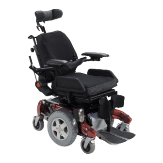
Key features 1) Headrest (adjustment clamping lever is located behind the headrest) 2) Slide grip 3) Backrest 4) Knob for adjusting armrest angle 5) Disengaging lever 6) Drive wheel 7) Armrest 8) Remote 9) Legrests... -
Page 22: Getting In And Out Of The Wheelchair
Getting in and out of the wheelchair Important information when side transferring in and out of the wheelchair In order to side transfer it is necessary for the armrest to either be raised or removed completely depending on the model. A skirtguard can be installed as an option in connection with the parallel sliding armrest. -
Page 23: Raise The Parallel Sliding Armrest / Remove The Skirtguard (Optional)
Raise the parallel sliding armrest / remove the skirtguard (optional) Swivel up armrest Swivel armrest up to access from the side. Removing the skirtguard (optional) to get on: Loosen clamping lever (1) Remove the skirtguard from the receptacle. - Page 24 Getting into the wheelchair: Position your wheelchair as close as possible to your seat. This might have to be done by an attendant. Switch your wheelchair off. Apply the hand brake of your wheelchair (if existing). Detach the side part of your wheelchair or swivel it up. Now slide into the wheelchair.
-
Page 25: Driving
Driving Before driving for the first time... Before you take your first trip, you should familiarise yourself well with the operation of the vehicle and with all operating elements. Take your time to test all functions and driving modes. NOTE: If installed, use the restraining systems (seat belts) each time you use the vehicle. -
Page 26: Taking Obstacles
5.2.1 The ”SureStep“ System The Invacare® Typhoon is fitted with "SureStep" technology. When climbing over obstacles, the front steering wheels are raised using the torque generated by the drive wheels. Please note that the techniques required for overcoming obstacles for wheelchairs fitted with central drives and "SureStep"... -
Page 27: The Components Of The "Surestep" And The "Stability Lock" System
5.2.3 The components of the "SureStep" and the "Stability Lock" system The diagram below shows the components in the "SureStep" system with the side panels removed. (1) Anti-Dive Spring, (2) Walking Beam und (3) Stability Lock. 5.2.4 Maximum obstacle height Your wheelchair can overcome obstacles and kerbs with the following heights. -
Page 28: Safety Information When Ascending Obstacles
5.2.5 Safety information when ascending obstacles CAUTION: Danger of Tipping Over! Never approach obstacles at an angle! Put your backrest into an upright position before climbing an obstacle! CAUTION: The wheelchair can be damaged if an obstacle is approached at excessive speed. -
Page 29: The Correct Way To Overcome Obstacles
5.2.7 The correct way to overcome obstacles CAUTION: If the lifter is raised, the drive wheels can lose ground contact when descending from obstacles or driving on an uneven surface! The "Stability Lock" prevents “Walking Beam“ spring deflection when the lifter is raised! Never descend from obstacles when the lifter is raised or drive on an uneven surface! In the event of the drive wheels losing ground contact, the lifter must be lowered so that the drive wheels come into contact with the ground again. -
Page 30: Driving Up And Down Gradients
Driving up and down gradients The Invacare® Typhoon has a maximum hill-climbing ability without overturning of 20%. WARNING: Danger of tipping over! Only ever drive downhill at a maximum of 2/3 of the top speed! Avoid sudden changes of direction or abrupt braking when driving on slopes! -
Page 31: Pushing The Wheelchair By Hand
Pushing the wheelchair by hand The motors of the wheelchair are equipped with automatic brakes, preventing that the wheelchair starts rolling out of control when the joystick box is switched off. When pushing the wheelchair, the magnetic brakes must be disengaged. Manually disengaging conventional motors Danger of the vehicle running away! When the motors are disengaged (for push operation), the electromagnetic motor brakes are... -
Page 32: Electrically Disengaging Gb Motors
Electrically disengaging GB motors CAUTION! Danger of the wheelchair rolling away! The motor brakes do not function in disengaged condition (push mode)! The pushbutton for disengaging the motors must never be fixed in its pushed-in position using adhesive tape etc! The pushbutton for disengaging the motors is located on the push handle. -
Page 33: Manually Disengaging Gb Motors (Emergency Disengaging)
Manually disengaging GB motors (emergency disengaging) Danger of the vehicle running away! When the motors are disengaged (for push operation), the electromagnetic motor brakes are deactivated! When the vehicle is parked, the levers for engaging and disengaging the motors must without fail be locked firmly into the "DRIVE" position (electromagnetic motor brakes activated)! The lever for disengaging the motors is located behind the right-hand drive wheel. -
Page 34: The Rem 24 Sd Remote
The REM 24 SD Remote Layout of the remote Upper side Controls Immobilizer "Activate / scroll through drive mode" button Horn Left-hand indicator Joystick "Activate / scroll through adjustment mode" button ON/OFF button Light Right-hand indicator 10) Hazard warning signal flasher... - Page 35 Upper side Displays 11) Battery charger display 12) Status display (in key symbol) 13) Drive mode display 14) Left-hand indicator display 15) Hazard warning signal flasher display 16) Light display 17) Right-hand indicator display...
- Page 36 Underside 1) Charger socket 2) Programming socket Rear panel Socket for Buddy button 1 (corresponds to "Activate / scroll through drive mode" button). Socket for Buddy button 2 (corresponds to "ON/OFF" button) Socket for Buddy button 3 (corresponds to "Activate / scroll through adjustment mode"...
-
Page 37: On/Off Diode (Status Display)
ON/OFF diode (status display) INFORMATION The ON/OFF diode (in key symbol) also serves as status or error message display. For error codes please see chapter "Error codes and diagnostic codes" on page 46. Battery charger display All diodes illuminated: Full range Only red diodes illuminated: Reduced range Both red diodes flashing:... -
Page 38: Activating / Deactivating The Immobilizer
Activating the immobilizer Switch on the remote. Use the end of the magnetic key (Invacare® Logo) to move over the sensor area (1) on the remote (key symbol). The horn will sound briefly once. The remote shuts down automatically. The immobilizer is activated. -
Page 39: Using The Buddy Buttons With The Remote
Using the Buddy buttons with the remote What is a Buddy button? A Buddy button is an additional sensing device that can be used to activate a remote function. The sockets for Buddy buttons are to be found at the rear of the remote. Socket 1 (corresponds to the ""Activate / scroll through drive mode""... -
Page 40: Controlling The Wheelchair Using The Remote
Can the electronic system programming be adapted? The electronic controller is programmed with standard values during manufacture. Your Invacare® dealer can carry out programming tailored to fit your requirements. Will the wheelchair not drive after switching on? Check the drive-away lock (see chapter "Activating / deactivating the immobilizer " on page... -
Page 41: How A Wheelchair With "Indirect Steering" Reacts To Joystick Movements
7.6.1 How a wheelchair with "Indirect Steering" reacts to joystick movements. "Indirect Steering" occurs by individually applying power to the drive wheels, and is found on wheelchairs with front, rear and middle wheel drive. Travel direction Note: To brake quickly, simply let go of the joystick. It will then automatically return to the middle position. -
Page 42: Operating The Electric Adjustment Options
Operating the electric adjustment options Electric adjustment options, like electric legrests or an electric backrest, are operated by using the joystick. 7.7.1 Activating adjustment mode Press the "activate / scroll through adjustment mode" button (A). The remote switches to the adjustment mode last used. The driving mode display (B) switches to the appropriate symbol (one of the symbols shown below). -
Page 43: Selecting And Operating The Adjustment Option
ECU mode (environment control unit). The standard REM 24 SD programming only supports the adjustment function. Please speak to your Invacare dealer if you have any questions in this respect. 7.7.2... -
Page 44: Changing Back To Driving Mode
7.7.3 Changing back to driving mode Briefly press the "Activate / scroll through driving mode" button (A). The remote switches back to the driving mode last used. The driving mode display indicates the drive level (B). -
Page 45: Error Diagnosis
Error diagnosis In the event that the electronics should show signs of failure, please consult the following troubleshooting guide in order to locate the error. INFORMATION Before beginning with the diagnosis, please ensure that the drive electronics are switched on. If the status display is OFF: Please check whether the drive electronics are SWITCHED ON. -
Page 46: Error Codes And Diagnostic Codes
7.8.1 Error codes and diagnostic codes The drive electronics are capable of rectifying some errors automatically. In this case the status display will cease to flash. Please switch the remote on and off several times. Wait approx. 5 seconds each time before switching the remote on again. If this does not rectify the error, locate the error using the flash codes shown below. - Page 47 FLASH FAULT CODE Error/brake error on right motor. Connection loose/faulty or motor faulty. Motors uncoupled Error/brake error on left motor. Connection loose/faulty or motor faulty. Battery totally discharged. Battery voltage too high. 9 or 10 Faulty data transmission between modules. Motors overstressed.
-
Page 48: Adjusting The Wheelchair To The User's Seating Posture
Adjusting the wheelchair to the user's seating posture CAUTION: Wheelchair damage and risk of accident! Collisions can occur between the legrest and the chassis or between the foot plates and the ground in the event of varying adjustment option combinations! This occurs in particular on wheelchairs with lifter and a seat angle adjustment range of -10°... -
Page 49: Adjusting The Armrests And The Joystick Box
Adjusting the armrests and the joystick box 8.2.1 Adapting the remote to the length of the user’s arm Requirements: Allen key 3 mm Loosen the socket head screw (1). Set remote to the desired length by pushing forward or backward. Tighten screw. -
Page 50: Setting The Height Of The Remote
8.2.2 Setting the height of the remote Loosen one or both of the wing screws (1 and 2) that allow height adjustment of the joystick box. Adjust the joystick box to the desired height. Re-tighten the screw(s). -
Page 51: Setting The Height Of The Armrests
8.2.3 Setting the height of the armrests Loosen the release handle (1). Set the armrest at the desired height. Tighten the release handle. -
Page 52: Setting The Width Of The Armrests
8.2.4 Setting the width of the armrests The distance between the armrests can be adjusted by 5.5 cm on both sides (totalling 11 cm). Requirements: Allen key 8 mm Where to find the adjustment screws The figure below shows the position of the screw (1) which allows armrest width adjustment (only the left side is shown in the illustration). - Page 53 Doing the adjustment Loosen screw (1) Adjust armrest to required position. Retighten the screw. Repeat this procedure for the second armrest.
-
Page 54: Manually Adjusting The Seat Tilt
Manually adjusting the seat tilt The manual seat angle adjustment has an adjustable range of 0° to 15°. The seat angle is adjusted by means of a spindle, which is to be found at the front underneath the seat frame. When adjusting the seat angle it should be ensured that at least 1cm of the threaded bolt always remains inside the spindle and is not completely unscrewed from the spindle. - Page 55 Loosen the counternut (1) on the spindle. Set the seat angle by turning the spindle (2). Tighten the counternut.
-
Page 56: Manually Adjusting The Backrest
Manually adjusting the backrest 8.4.1 Adjusting the backrest using the gas pressure spring The lever for adjusting the backrest is located on the opposite side from the Joystick Box under the armrest. The angle can be adjusted continuously between 0° and 30°. Adjusting angle of the backrest Pull lever (1) upward. -
Page 57: Adjust The Backrest Using The Perforated Plate
8.4.1.1 Adjust the backrest using the perforated plate The angle of the backrest has six positions, from -10° to +30°. Unscrew the hand screws (1) on both sides. The backrest is adjusted by choosing a combination of one of the two bore holes in the backrest frame and one of the six bore holes in the fixing plate. -
Page 58: Flex And Contour Seats
8.4.2 Flex and Contour Seats Set the angle by turning the hand wheel (1). -
Page 59: The Lifter
The Lifter The electric lifter is operated via the remote. Please see chapter "Operating the electric adjustment options" on page 42. Please note – Speed restriction The lifter is equipped with sensors that reduce the drive speed of the wheelchair as soon as the lifter is raised or lowered above a certain point. -
Page 60: Explanation Of Symbols On Lifter Warning Sticker
8.5.1 Explanation of symbols on lifter warning sticker. Do not lean out Do not drive up when the lifter is or down slopes raised! when the lifter is raised! Do not allow any Never drive with body parts to get two people! under a raised seat! -
Page 61: Legrests
Legrests 8.6.1 Electric legrest The electric legrest is operated via the remote. Please see chapter "Operating the electric adjustment options" on page 42. The electric legrest can be lowered completely to assist getting out of the wheelchair. To do so, move your seat into the correct position by lowering the lifter or by means of a negative seat angle (tilted slightly to the front). -
Page 62: Adjustable Legrest
8.6.2 Adjustable legrest 8.6.2.1 Adjusting the angle Prerequisites: 1x 10 mm open-ended spanner Use the open-ended spanner to loosen the counternut (1). Move the legrest to the desired position by turning the spindle (2). Tighten the counternut. -
Page 63: Adjusting The Length Of The Legrest
8.6.2.2 Adjusting the length of the legrest Prerequisites: 1x 5 mm socket head spanner Use the socket head spanner to loosen the fastening screws (1). Slide the foot support to the desired height. Tighten the fastening screws. -
Page 64: Adjusting The Calf Plate To The Calf Width Of The User
8.6.2.3 Adjusting the calf plate to the calf width of the user The calf plate of the legrest can be adapted to the user’s calf width by bending apart or together. Bending the calf plate to the desired width. -
Page 65: Adjusting The Angle Of The Foot Plate
8.6.2.4 Adjusting the angle of the foot plate Prerequisites: 1x 5 mm socket head spanner Fold up the foot plates in order to access the adjusting screws. Use the socket head spanner to adjust the adjusting screws (1). Fold the foot plate down again. -
Page 66: Electrical System
Electrical System Electronics Protection System The vehicle's electronics are equipped with an overload-protection system. If the motors are put under considerable strain for a longer period of time (for example, when driving up a steep hill) and especially when the ambient temperature is high, then the electronic system could overheat. -
Page 67: The Main Fuse
The main fuse NOTE A defective main fuse may be replaced only after checking the entire electric system. An Invacare® specialised dealer must perform the replacement. All electrical equipment fitted to the wheelchair is protected against overload by the main fuse. -
Page 68: Batteries
Batteries 9.2.1 What you need to know about batteries Power is supplied by two 12V gel batteries. The batteries are maintenance-free and only need regular charging. New batteries should always be fully charged once before their first use. New batteries will be at their full capacity after having run through approx. - Page 69 The batteries cannot be overcharged with the specified charger. Please use only charging devices in Class 2. This class of chargers may be left unattended during charging. All charging devices which are supplied by Invacare® and comply with these requirements.
-
Page 70: Charging The Batteries
Danger of explosion and destruction of batteries if the wrong battery charger is used! Only ever use the battery charger supplied with your vehicle, or a charger that has been approved by Invacare®! Danger of electric shock and damage to the battery charger if it is allowed to get wet! - Page 71 Charging the batteries Switch off the wheelchair at the Joystick Box. Connect the battery charger to the Joystick Box - the charging socket is located on the bottom of the Joystick Box (1). Connect battery charger to the mains outlet and switch on if necessary.
-
Page 72: Removing And Fitting Batteries
9.2.3 Removing and fitting batteries WARNING: Danger of injury if the batteries are not handled correctly during assembly and maintenance work! New batteries should be installed by authorised technicians! Observe the warnings on the batteries! Take into account the heavy weight of the batteries! Only ever use the battery type defined in the technical specifications! Danger of fire and burns if battery terminals are short-circuited! DO NOT short-circuit battery terminals with a tool! -
Page 73: Removing The Batteries
9.2.3.1 Removing the batteries CAUTION: Risk of fire and burns if battery poles are bridged! When replacing the batteries the battery poles MUST NOT come into contact with metal parts of the wheelchair causing bridging. Be sure to replace the battery pole caps after the batteries have been replaced. Requirements: 6mm Allen key 5 mm Allen key... - Page 74 Use the 6mm Allen key to loosen and remove the screws (1) on both sides. Pull cover to the front and remove.
- Page 75 Remove the locking clip (1) using the needle-nosed pliers and pull out the retaining pin of the actuator or spindle retainer (on manual seat angle adjustment) (2)
- Page 76 Use the 5mm Allen key to loosen and remove the screws (1) on both sides. Pull the holding plate to the front and remove. Pull out the actuator or spindle (on manual seat angle adjustment) (1) to the front.
- Page 77 Release and remove the battery cable on the battery poles. Remove batteries by pulling to the front.
- Page 78 NOTE Installation of new batteries is carried out in reverse order. Releasing the lifter locking mechanism If lifter is fitted raise the piston rod of the actuator carefully on the remote until the piston head (1) interlocks in the retainer track (2). The lifter is now supported by the actuator.
-
Page 79: How To Handle Damaged Batteries Correctly
Only ever transport damaged batteries in an appropriate acid-resistant receptacle. Wash all objects that have come into contact with acid with lots of water. Disposing of dead or damaged batteries correctly Dead or damaged batteries can be given back to your dealer or directly to Invacare®. -
Page 80: Care And Maintenance
Care and maintenance NOTE: Have your vehicle checked once a year by an authorised Invacare® dealer in order to maintain it's driving safety and roadworthiness. Cleaning the vehicle When cleaning the vehicle, pay attention to the following points: Only use a damp cloth and gentle detergent. - Page 81 Maintenance Jobs Seat and backrest padding: - Check for perfect condition. Side part and armrest: - Are all fastening elements installed? - Can armrests / side parts be removed and installed without too much physical effort? - Are armrests secured in their positions? Legrests: - Do legrests lock into place without any problem? (Only applies to detachable legrests)
- Page 82 If the wheelchair is serviced at regular intervals, damaged or worn parts can be located and replaced in time, thus preserving it in good working order. A complete checklist of necessary maintenance work can be found in the Service Manual, which can be obtained from Invacare®. Maintenance Jobs Before every trip...
-
Page 83: Repair Instructions
The following are instructions on repairs that can be performed by the user. For the specifications of spare parts please see "Technical Specifications" on page 92, or consult the Service Manual, available from Invacare®. In case you require assistance, please contact your Invacare® Dealer. 11.1... -
Page 84: Repairing Punctures (Drive Wheel With Conventional Motor And Pneumatic Tyres)
11.1.1 Repairing punctures (drive wheel with conventional motor and pneumatic tyres) Injury hazard! If the wheel has been insufficiently tightened during assembly, it can become loosened during driving! When reassembling the drive wheels, tighten the Allen screws at a torque of 30 Nm! Secure all screws using a suitable blocker (e.g. - Page 85 Removing the wheel Block up the vehicle (place wooden blocks under frame). Unscrew 4 screws (1). Remove the wheel from the hub. NOTE: Re-assembly is done in reverse order. Ensure that the tyre is replaced on the same side and in the same travel direction as it was previously mounted.
- Page 86 Repairing the flat tyre Unscrew valve cap. Depressurise tyre by pressing in the pin in the valve . Remove the 5 cylinder head screws (back of the wheel, 2. Remove the rim halves from the tyre. Remove the inner tube from the tyre. Repair inner tube and replace, or insert new.
-
Page 87: Repairing Punctures (Drive Wheel With Gb Motor And Pneumatic Tyres)
11.1.2 Repairing punctures (drive wheel with GB motor and pneumatic tyres) EXPLOSION HAZARD! The wheel will explode if you do not let the air out of the tyre before removing the wheel! Always let the air out of the tyre before removing it (press in the pin in the middle of the valve)! Injury hazard!If the wheel has been insufficiently tightened during assembly, it can become loosened during driving! - Page 88 Disassembly Block up the vehicle (place wooden blocks under frame). Unscrew valve cap. Depressurise tyre by pressing in the pin in the valve (1). Unscrew 5 screws (2). Remove the wheel rim halves. Remove the inner tube from the tyre. NOTE: If the old inner tube is to be repaired and re-used, and has become wet during repair, you can make replacement easier by sprinkling the inner tube with a little talcum powder.
- Page 89 Repair inner tube and replace, or insert new. Replace the inner tube in the tyre. Insert the wheel rim halves once again. Insert the screws and tighten slightly. Pump a little air into the inner tube. Screw the wheel rims tightly together. Ensure that the tyre outer is seated correctly.
-
Page 90: Refurbishment
Cleaning and disinfection. Please see chapter "Care and maintenance" on page 80. Inspection according to service plan. Please consult service instructions, available from Invacare®. Adaptation to the user. Please see chapter "Adjusting the wheelchair to the user's seating posture" on page 48. -
Page 91: Disposal
Disposal The equipment wrapping is potentially recyclable. The metal parts are used for scrap metal recycling. The plastic parts are used for plastic recycling. Electric components and printed circuit boards are disposed of as electronic scrap. Disposal must be carried out in accordance with the respective national legal provisions. Ask your city or district council for details of the local waste management companies. -
Page 92: Technical Specifications
Technical Specifications Electrical system 6 km/h version Motors Batteries Main fuse Charging device Output current Output voltage Input voltage Operating temperature (surroundings) Storage temperature Tyres Tyre pressure Driving characteristics Speed Max. hill-climbing ability without overturning Max. climbable obstacle height Turning radius Drive range in accordance with ISO 7176 ***... - Page 93 Dimensions Total height Width of chassis Overall width of the seat (with standard armrests) Seat width 39 cm Seat width 43 cm Seat width 48 cm Overall width of the seat (with parallel sliding armrests) Seat width 39 cm Seat width 43 cm Seat width 48 cm Overall length (incl.
- Page 94 Dimensions Seat depth Backrest height **** Seat cushion thickness Backrest angle Armrest height Leg support lengths Short (for leg length 32-38 cm) Medium (for leg length 38-44 Long (for leg length 44-50 cm) Seat angle, electronic adjustment (wheelchair without lifter) Seat angle, manual adjustment (wheelchair without lifter) Seat angle, electronic adjustment...
- Page 95 ** Width adjustable for side panel adjustment. *** Note: The drive range of an electric wheelchair is strongly influenced by external factors, such as the charging state of the batteries, surrounding temperature, local topography, road surface characteristics, tyre pressure, weight of driver, drive style and use of batteries for lighting, servos etc.
-
Page 96: Inspections Performed
It is confirmed by stamp and signature that all jobs listed in the inspection schedule of the Service and Repair Instructions have been properly performed. The list of the inspection jobs to be performed can be found in the Service Manual which is available through Invacare®. Delivery Inspection... - Page 97 Order No. of this Manual: 1435058.DOC Release Date: 01.03.04 English...