Advertisement
Available languages
Available languages
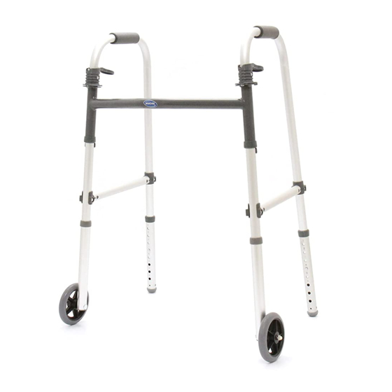
Leg Extensions and Wheeled Walker Accessories
Assembly, Installation and Operating Instructions
Model Nos. 6278, 6275, 6266, 6268, 6267, 6272, 6273,
'6264, 6265, 6263, 6264P, 6265P, 6270, 6271, 6274, and 6372
NOTE: Check ALL parts for shipping damage. If shipping damage is noted, DO NOT use. Contact
carrier/dealer for further instruction.
To ensure the safe and proper installation of the Leg Extensions and Wheeled Walkers, these
instructions MUST be followed:
NOTE: Invacare recommends the leg accessory combinations indicated on the chart by an "X".
FRONT
WHEELS
MODEL NOS.
6273
3-inch Swivel
6267
5-inch Swivel
6270**
3-inch Fixed
6271**
5-inch Fixed
6372***
5-inch Fixed Dual
Wheels
6277
Tall 3-inch Fixed
Tall Leg Extensions
(Kit Only)
NOTE: When adding wheeled accessories to the walker, you must have front wheels installed BEFORE
adding rear leg extension options.
NOTE: Front wheels can be used in conjunction with the rear glide tips included or by adding the
allowable rear wheel option as shown in the chart above.
NOTE: When using 5 inch swivel accessories on the front of the walker, 13 inch rear leg accessories must
be used. Otherwise, height adjustment will be limited.
*NOTE: There are ONLY four kits available which allow you to order one number to get both FRONT
wheels and rear leg extensions. All other available combinations must be ordered individually.
**NOTE: Model nos. 6270, 6271, 6263, 6264, 6264P, 6265, 6265P, and 6274 can be ONLY used with
model no. 6291‐HDA Heavy‐Duty Walker.
***NOTE: Model no. 6372 can ONLY be used with model no. 6441‐A Bariatric Walker.
For more information regarding Invacare products, parts, and services, please visit www.invacare.com
Part No 1118382
SAVE THESE INSTRUCTIONS
Safety Summary
REAR LEG EXTENSION
OPTIONS MODEL NOS.
6265**
6263**
6264P**
13-inch
10-inch
Sure
Brakes with
Glide
Wheels
X
X
X
X
X
1
6265**
6265P**
6266
13-inch
13-inch
Brakes with
Leg
Wheels
Extension
X
X
X
X
X
X
X
X
X
*KIT MODEL
NOS.
6274**
Kit = Front
10-inch
Wheel Model +
Sure
Rear Leg Ext.
Glide
Model
*6272=6273+6263
*6269=6273+6266
*6268=6267+6263
X
NA
X
NA
NA
*6278=6277+6266
6275=6266+6266
(with Rubber Tips)
Leg Extensions and
Wheeled Walker Accessories
Advertisement
Table of Contents

Related Manuals for Invacare 6264P


Summary of Contents for Invacare 6264P
-
Page 1: Safety Summary
NOTE: When adding wheeled accessories to the walker, you must have front wheels installed BEFORE adding rear leg extension options. NOTE: Front wheels can be used in conjunction with the rear glide tips included or by adding the allowable rear wheel option as shown in the chart above. NOTE: When using 5 inch swivel accessories on the front of the walker, 13 inch rear leg accessories must be used. Otherwise, height adjustment will be limited. *NOTE: There are ONLY four kits available which allow you to order one number to get both FRONT wheels and rear leg extensions. All other available combinations must be ordered individually. **NOTE: Model nos. 6270, 6271, 6263, 6264, 6264P, 6265, 6265P, and 6274 can be ONLY used with model no. 6291‐HDA Heavy‐Duty Walker. ***NOTE: Model no. 6372 can ONLY be used with model no. 6441‐A Bariatric Walker. For more information regarding Invacare products, parts, and services, please visit www.invacare.com Part No 1118382 Safety Summary REAR LEG EXTENSION OPTIONS MODEL NOS. 6265** 6265** 6264P** 6265P** 6266 10-inch... -
Page 2: Installation Warning
Wheel Accessories are ONLY to be used on the front walker legs with exception of Model No(s). 6264, 6264P - 10 inch Rear Wheel Brakes and 6265, 6265P - 13 inch Rear Wheel Brakes. - Page 3 Installing Fixed Wheel Attachments/Leg Extensions NOTE: For this procedure, refer to FIGURE 1. NOTE: Refer to Installation Warning on page 2. 1. Press the snap buttons on the walker frame to remove the two existing front leg extensions from the walker. NOTE: The front leg extensions will not be reassembled to the walker when using the wheel attachments/leg extensions. NOTE: For 3 and 5 inch fixed wheels (model nos. 6270, 6271, and 6278), position the wheels on the outside of walker. 2. Press the snap button on the walker frame and install the new wheel attachment/leg extension onto front leg of the walker. 3. Repeat STEP 2 for remaining front leg. 4. Adjust the wheel attachment/leg extension to one of the adjustment holes. 5. Perform one of the following: • Install the rear leg extension options, if necessary. Refer to Installing Rear Leg Extension Options on page 4. • Remove rear rubber tips and replace with glide tips included. Refer to Installing the Glide Tip on page 4. NOTE: When using 10 inch rear leg extensions, the adjustment ranges are reduced on Model Nos. 6273 and 6267. 6. Ensure that the snap button of each leg fully protrudes through the desired adjustment hole and legs are adjusted so the walker is level. DETAIL “A” - MODEL NOS. 6270, 6271, AND 6372 Front Walker...
- Page 4 NOTE: The rear leg extensions will not be reassembled to the walker when using the rear wheel attachments. 2. Press the snap button on the walker frame and install the new wheel attachment/leg extension onto rear leg of the walker. 3. Repeat STEP 2 for remaining rear leg. 4. Adjust the wheel attachment/leg extension to one of the adjustment holes. 5. Repeat STEP 4 for remaining wheel attachment/leg extension. 6. Ensure that the snap button of each leg fully protrudes through the desired adjustment hole and legs are adjusted so the walker sits level. DETAIL “A” - MODEL NOS. 6264, 6264P, 6265, AND 6265P Adjustment Brake Holes with Wheel NOTE: Brake with wheel is on same side of adjustment holes on model nos. 6264 and 6265. FIGURE 2 Installing Rear Leg Extension Options Installing the Glide Tip NOTE: For this procedure, refer to FIGURE 3 on page 5.
- Page 5 NOTE: When properly installed, the tube edge will rest inside the top edge of the new glide tip. If the tube edge is visible, the tip is not properly installed. 3. Insert the new glide tip firmly into the leg extension. 4. Ensure the new glide tip is properly installed as shown in Detail ʺAʺ of FIGURE 3. If necessary, tap new glide tip into position. 5. Press the snap button and install the leg extension with new glide tip onto the walker frame leg. Ensure that the snap button of each leg fully protrudes through the desired adjustment hole and legs are adjusted so the walker sits level. 6. Repeat STEPS 1‐5 on remaining rear leg extension. Replacing Fixed Wheels/Swivel Casters NOTE: For this procedure, refer to FIGURE 4 on page 6. NOTE: Refer to Installation Warning on page 2. Fixed Wheels - Model Nos. 6270 and 6271 1. Position one wrench on the hex screw and remove the locknut by using the other wrench and turning counterclockwise.
- Page 6 Tightening Swivel Casters NOTE: Refer to Installation Warning on page 2. 1. Remove swivel wheel attachments from front legs by depressing snap button. 2. Hold one swivel wheel attachment with the wheel up as shown in figure 4. 3. Turn hex nut clockwise with a wrench to tighten swivel caster. 4. Repeat STEPS 2‐3 for remaining swivel wheel attachment. 5. Press the snap buttons and slide the swivel wheel attachments onto the front legs of the walker. Ensure that the snap button of each leg fully protrudes through the desired adjustment hole and legs are adjusted so the walker sits level. Tube FIGURE 4 Replacing Fixed Wheels/Swivel Casters Leg Extensions and Wheeled Walker Accessories Wheel Swivel Caster Housing Adjustment Holes Snap-Button Part No 1118382...
-
Page 7: Limited Warranty
This warranty gives you specific legal rights and you may also have other legal rights which vary from state to state. Invacare warrants its product to be free from defects in materials and workmanship for five years (excluding tires and wheels) for the original purchaser. If within such warranty period any such product shall be proven to be defective, such product shall be repaired or replaced, at Invacare's option. - Page 8 NOTE: Lorsque vous ajoutez des accessoires à roues sur la marchette, vous DEVEZ installer les roues avant AVANT dʹajouter des options sur les rallonges de pattes arrière. NOTE: Les roues avant peuvent être utilisées avec les embouts patins arrière inclus ou en ajoutant lʹoption des roues arrière possible tel quʹindiqué sur le tableau ci‐dessous. NOTE: Lorsque vous utilisez les accessoires pivotants de 5 pouces à l’avant de la marchette, vous DEVEZ utiliser les accessoires pour les pattes arrière de 13 pouces, sans quoi le réglage de la hauteur sera limité. Pour plus de renseignements sur les produits, les pièces et les services de Invacare, visiter le site web www.invacare.com Rallonges de Pattes et Accessoires à Roues Pour Marchette ARRIÈRE MODÈLES NOS. 6266 6264P**...
-
Page 9: Avertissements Généraux
*NOTE: Il nʹy a que cinq ensembles disponibles,ce qui vous permet de commander un numéro pour obtenir les deux roues AVANT et les rallonges de patte ARRIÈRE. Toutes les autres combinaisons DOIVENT être commandées SÉPARÉMENT. **NOTE: Les numéros de modèles 6270, 6271, 6263, 6264, 6264P, 6265, 6265P et 6274 peuvent être UNIQUEMENT utilisés avec le déambulateur robuste 6291‐HDA. ***NOTE: Le numéro de modèle 6372 peut UNIQUEMENT être utilisé avec le déambulateur bariatrique 6441‐A. AVERTISSEMENTS GÉNÉRAUX NE PAS utiliser cet équipement ni aucune de ses options sans avoir au préalable lu et bien compris ces instructions ainsi que la documentation supplémentaire telle que les manuels de lutilisateur, les manuels d’entretien ou les fiches de mode d’emploi fournies avec ce produit ou avec ses options. - Page 10 AVANT l'utilisation. Les accessoires à roues doivent être utilisés SEULEMENT sur les pattes avant de la marchette, sauf pour les modèles 6264P - freins de roue arrière 10 po. et 6265P - freins de roue arrière 13po. AVERTISSEMENTS POUR ACCESSOIRES Les produits Invacare sont spécifiquement conçus et fabriqués pour être utilisés avec...
- Page 11 6. Sʹassurer que le bouton à ressort de chaque patte ressort complètement de lʹorifice de réglage choisi et que les pattes sont réglées de façon à ce que la marchette soit de niveau. SCHÉMA “A” - MODÈLES NOS. 6270, 6271, ET 6372 Avant Châssis de la marchette Bouton à ressort Tube de la patte Écrou de Roue blocage Rondelles NOTE: Le numéro de modèle 6372 comporte des roues doubles sur les pieds avant droit et gauche. FIGURE 1 Installer les Attaches de Roue/Rallonges de Pattes Installer les Options des Rallonges de Pattes Arrière NOTE: Pour cette procédure, se référer à la FIGURE 2.
- Page 12 SCHÉMA “A” - MODÈLES NOS. 6264, 6264P, 6265 AND 6265P Trous de réglage Frein NOTE: La roue à frein se trouve du même côté que les trous de réglage sur les numéros de modèles 6264 et 6265. FIGURE 2 Installer les Options des Rallonges de Pattes Arrière Installer le Patin NOTE: Pour cette procédure, se référer à la FIGURE 3. NOTE: Se référer à Avertissements pour lʹInstallation de la page 10. 1. Enfoncer les poussoirs sur le châssis de la marchette et enlever la rallonge de patte ...
- Page 13 Remplacer les Roues Fixes/Roulettes Pivotantes NOTE: Pour cette procédure, se référer à la FIGURE 4 de la page 13. NOTE: Se référer à Avertissements pour lʹInstallation de la page 10. Roues fixes - Modèles Nos. 6270 et 6271 1. Placer une des clés sur la vis hexagonale et enlever lʹécrou de blocage en utilisant lʹautre clé en tournant dans le sens contraire de aiguilles dʹune montre. 2. Enlever les rondelles, la roue, la bague et la vis hexagonale qui fixent la roue à la rallonge de la patte. 3. Vérifier si les rondelles, la bague et la vis hexagonale sont usées et/ou endommagées, et remplacer si nécessaire. 4. Pour installer la nouvelle roue, inverser les ÉTAPES 1‐2. Roulettes Pivotantes - Modèles Nos. 6273 et 6267 1. Saisir le tube de la patte, et placer la clé sur lʹécrou hexagonal. 2. Desserrer la roulette pivotante et dévisser du logement de la roulette pivotante. 3.
- Page 14 NOTES Rallonges de Pattes et Accessoires Part No 1118382 à Roues Pour Marchette...
-
Page 15: Garantie Limitée
Cette garantie n’inclut pas les frais de main d’œuvre ou de transport encourus lors de la réparation ou de l’installation de la pièce de rechange dudit produit. En vertu de cette garantie, la réparation et/ou le replacement susmentionnés constituent la seule obligation d’Invacare et le... - Page 16 L4Z 4G4 Canada 800-333-6900 800-668-5324 All rights reserved. Trademarks are identified by the symbols ™ and ®. All trademarks are owned by or licensed to Invacare Corporation unless otherwise noted. © 2008 Invacare Corporation Part No 1118382 Rev D - 06/08...