Sony UWP-V1 Operating Instructions Manual
Wireless microphone package
Hide thumbs
Also See for UWP-V1:
- Service manual (164 pages) ,
- Operating instructions manual (72 pages) ,
- User manual (12 pages)
Table of Contents
Advertisement
Wireless Microphone
Package
For U30/U42/CE33/CE38/CE42/CE57/CE62/CE67 models only
The supplied CD-ROM includes the Operating Instructions for the UWP-V1/V2/
V6/X7/X8 Wireless Microphone System (English, French, German, Italian, and
Spanish versions) and the frequency lists in PDF format.
For more details, see "Using the CD-ROM Manual (U30/U42/CE33/CE38/
CE42/CE57/CE62/CE67 Models only)" on page 19.
Operating Instructions
Before operating the unit, please read this manual thoroughly
and retain it for future reference.
UWP-V1/V2/V6
UWP-X7/X8
© 2008 Sony Corporation
3-870-284-15 (1)
Advertisement
Table of Contents

Related Manuals for Sony UWP-V1


Summary of Contents for Sony UWP-V1
-
Page 1: Operating Instructions
Wireless Microphone Package For U30/U42/CE33/CE38/CE42/CE57/CE62/CE67 models only The supplied CD-ROM includes the Operating Instructions for the UWP-V1/V2/ V6/X7/X8 Wireless Microphone System (English, French, German, Italian, and Spanish versions) and the frequency lists in PDF format. For more details, see “Using the CD-ROM Manual (U30/U42/CE33/CE38/ CE42/CE57/CE62/CE67 Models only)”... - Page 2 AVERTISSEMENT operate this equipment. N’exposez pas les batteries à une chaleur excessive, au soleil ou près d’un feu par Use of Sony wireless devices is regulated exemple. by the Federal Communications Commission as described in Part 74 subpart Si l’émetteur dégage une température H of the FCC regulations and users anormalement élevée, une odeur de brûlé...
- Page 3 Industry Canada Für Kunden in Europa technical specifications were met. Bevor Sie dieses Gerät benutzen, lesen Sie Use of Sony wireless devices is regulated bitte das separate die R&TTE-Richtlinien by the Industry Canada as described in their behandelnde Dokument.
- Page 4 Record távközlési berendezésekkel kapcsolatos the model and serial numbers in the space óvintézkedéseket ismertető R&TTE provided below. dokumentumot. Refer to these numbers whenever you call upon your Sony dealer regarding this product. Model No. _____________________ Serial No. _____________________...
- Page 5 WARNING (URX-P2) Si el sintonizador desprende temperaturas altas no normales, olor a quemado o humo Batteries shall not be exposed to excessive durante su uso, quite el soporte de las pilas heat such as sunshine, fire or the like. y detenga el uso del sintonizador inmediatamente.
- Page 6 Canada sont Trade Name : SONY remplies. Model : URX-P2/M2 Responsible party : Sony Electronics L’usage des appareils sans fil Sony est Inc. réglementé par l’Industrie Canada comme Address : 16530 Via Esprillo, décrit dans leur Cahier des Normes San Diego, CA 92127 U.S.A.
- Page 7 URX-P2/M2 tyyppinen laite on direktiivin 1999/5/EY oleellisten vaatimusten ja sitä Para los clientes de Europa koskevien direktiivin muiden ehtojen Por medio de la presente Sony Corporation mukainen. declara que el URX-P2/M2 cumple con los Halutessasi lisätietoja, käy osoitteessa: requisitos esenciales y cualesquiera otras http://www.compliance.sony.de/...
- Page 8 és az 1999/5/EC http://www.compliance.sony.de/ irányelv egyéb előírásainak. Za stranke v Evropi További információkat a következő weboldalon találhat: Sony Corporation izjavlja, da je ta http://www.compliance.sony.de/ URX-P2/M2 v skladu z bistvenimi zahtevami in ostalimi relevantnimi določili direktive 1999/5/ES. Za podrobnosti vas naprošamo, če pogledate naURL: http://www.compliance.sony.de/...
- Page 9 WARNUNG (URX-P2) Zu hoher Schalldruck von Ohrhörern und Kopfhörern kann Gehörschäden verursachen. Um dieses Produkt sicher zu verwenden, vermeiden Sie längeres Hören bei sehr hohen Schalldruckpegeln. AVVERTENZA (URX-P2) Un’eccessiva pressione sonora da auricolari e cuffie può causare la perdita dell’udito. Per usare questo prodotto in maniera sicura, evitare l’ascolto prolungato a livelli eccessivi di pressione sonora.
-
Page 10: Table Of Contents
Table of Contents Configuration of the Packages ... 12 Attaching the supplied UWP-V1 ........ 12 accessory to the hand-held UWP-V2 ........ 13 microphone (UTX-H2) ..30 UWP-V6 ........ 14 Inserting the plug-on UWP-X7 ........ 15 transmitter (UTX-P1) into the UWP-X8 ........ 16 supplied soft case ....31... - Page 11 Configuration examples of the UWP-V1/V2/X7/X8 ....42 Configuration example of the UWP-V6 ........ 45 Error Messages ......46 Troubleshooting......47 Important Notes on Use ....50 On usage and storage ..... 50 On cleaning ......50 Specifications ....... 51 Transmitters (UTX-B2/H2/P1) ....
-
Page 12: Configuration Of The Packages
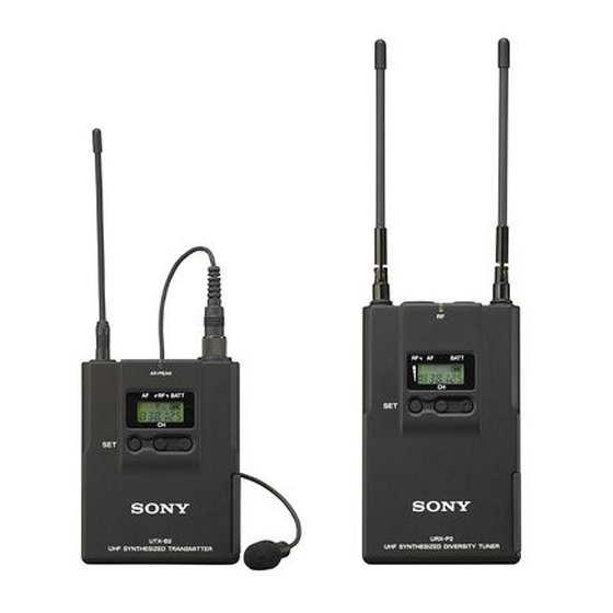
The UWP-V1 consists of a body-pack transmitter (UTX-B2), a portable diversity tuner (URX-P2), and their accessories. When used in conjunction with a compact camcorder, the UWP-V1 makes a mobile system for ENG (Electronic News Gathering) or EFP (Electronic Field Production) purposes. -
Page 13: Uwp-V2
(1) Operating Instructions (1) CD-ROM (1) (for U30, U42, CE33, CE38, CE42, CE57, CE62 and CE67 models) Sony Wireless Microphone Frequency List (1) (for AU66 and E models) Warranty card (1) (for U30 and U42 models) Configuration of the Packages... -
Page 14: Uwp-V6
UWP-V6 The UWP-V6 consists of a plug-on transmitter (UTX-P1), a body-pack transmitter (UTX- B2), a portable diversity tuner (URX-P2), and their accessories. When used in conjunction with a compact camcorder, the UWP-V6 makes a mobile system for ENG (Electronic News Gathering) or EFP (Electronic Field Production) purposes. -
Page 15: Uwp-X7
Operating Instructions (1) Belt clip (1) CD-ROM (1) (for U30, U42, CE33, CE38, CE42, CE57, CE62 and CE67 models) Sony Wireless Microphone Frequency List (1) (for AU66 and E models) Warranty card (1) (for U30 and U42 models) Configuration of the Packages... -
Page 16: Uwp-X8
Microphone holder (1) Operating Instructions (1) CD-ROM (1) (for U30, U42, CE33, CE38, CE42, CE57, CE62 and CE67 models) Sony Wireless Microphone Frequency List (1) (for AU66 and E models) Warranty card (1) (for U30 and U42 models) Configuration of the Packages... -
Page 17: Features
This tuner employs a space diversity system with little signal dropout and two angle- adjustable antennas. It comes with an Each of the UWP-V1/V2/V6/X7/X8 adapter for mounting the tuner on the wireless microphone packages (referred to compact camcorder (PMW-EX1, HDR-Z7, as the UWP series packages hereafter) etc.). -
Page 18: Uwp-X7
Body-pack transmitter (UTX- Diversity tuner module (URX- This is a small and lightweight transmitter This tuner module can be incorporated into with a crystal-controlled PLL (phase lock the MB-X6 Tuner Base Unit or SRP-X500P loop) synthesized system and a BMP-type Powered Mixer. -
Page 19: Using The Cd-Rom Manual (U30/U42/Ce33/Ce38/Ce42/Ce57/Ce62/Ce67 Models Only)
Insert the CD-ROM in your CD-ROM Using the CD- drive. A cover page appears automatically in ROM Manual (U30/ your browser. U42/CE33/CE38/ If it does not appear automatically in the browser, double-click on the CE42/CE57/CE62/ index.htm file on the CD-ROM. CE67 Models Select and click on the Operating Instructions or the frequency lists that... -
Page 20: Parts Identification
c Audio input connector Parts Connect the supplied lavalier microphone here. By using a commercially available Identification XLR-BMP conversion input cable, UTX- B2, the line output connector of the audio mixer or the microphone which does not require the external power supply can also be connected. -
Page 21: Hand-Held Microphone (Utx-H2)
E CH (channel) indication For details on how to insert the batteries, see “Power Supply” on page 27. Shows the transmission channel. Each time you press the SET button in transmission g + (+ selection) / – (– selection/reset) mode, the channel indication changes as buttons follows. -
Page 22: Power Indicator
a Power indicator mode, the channel indication changes as Lights up green when the microphone is follows. turned on. For details, see “Transmitter Settings” on page 39. b POWER switch Turns the power of the microphone ON or Transmission OFF. channel c Battery compartment Transmission... -
Page 23: Plug-On Transmitter (Utx-P1)
Plug-on transmitter (UTX- Audio input level INPUT selector position LINE Front side +8 dBV or more — On (red) –9 dBV or more — and less than +8 (green) Less than –9 dBV — –40 dBV or more On (red) —... -
Page 24: Portable Diversity Tuner (Urx-P2)
A AF (audio frequency) indication For details, see “Transmitter Settings” on page 39. Appears whenever the input audio signal is g POWER switch stronger than the reference level. Turns the power of the microphone ON or OFF. B RF (radio frequency) indication Appears during signal transmission from h Battery compartment the antenna. - Page 25 h Display section Note Do not connect headphones with a monaural mini jack. This may lead to short- circuiting of the headphone output, resulting in distorted sound output. c RF (radio frequency) indicator The color indicates the strength of the RF input signal.
-
Page 26: Diversity Tuner Module (Urx-M2)
i OUTPUT (audio output) connector c Display section (3.5-mm diameter stereo mini jack) Connect one end of the supplied XLR-BMP conversion output cable for the URX-P2 or the stereo mini plug-BMP conversion cable here and the other end to the microphone input on a camcorder, mixer, or amplifier. -
Page 27: Power Supply
Batteries can also be inserted in the portable Power Supply diversity tuner (URX-P2) in the same manner. Slide the battery-compartment catches inward (in the direction of the arrows b This section explains the power supply for B) to take out the battery holder. each component. - Page 28 Hand-held microphone (UTX- Turn the grip in the direction of the arrow to open the battery compartment. Align two new LR6 (size AA) alkaline batteries with the polarity markings and insert them into the battery compartment, and then close the cover. Align two new LR6 (size AA) alkaline batteries with the polarity markings and insert them into the battery...
- Page 29 Leakage left in the compartment and the component may cause poor battery contact. If there seems to be poor battery contact, consult your Sony dealer. CAUTION Danger of explosion if battery is incorrectly replaced. Replace only with the same or equivalent type recommended by the manufacturer.
-
Page 30: Attachment And Installation Procedures
To remove the belt clip Attachment and Installation Procedures This section describes the procedures for attaching the supplied accessories to the components and the installation of the diversity tuner module (URX-M2) into the Insert a pointed object such as a ballpoint MB-X6 Tuner Base Unit or SRP-X500P pen between the belt clip and the Powered Mixer. -
Page 31: Inserting The Plug-On Transmitter (Utx-P1) Into The Supplied Soft Case
To detach a microphone or a cable Inserting the plug-on transmitter (UTX-P1) into Microphone or cable connector the supplied soft case Release button Press the release button and pull off the microphone or cable slowly. Attaching the supplied accessories to the portable diversity tuner (URX-P2) Insert the UTX-P1 into the supplied soft case with the rear side up, and close the... -
Page 32: Installing A Diversity Tuner Module (Urx-M2)
To remove the shoe mount adapter While pushing on the “PUSH” marking on the shoe mount adapter (1), disengage the horizontal part of the belt clip from the horizontal groove on the shoe mount adapter (2). Then, push the shoe mount adapter in the direction of the arrow (3). - Page 33 To install a diversity tuner To install a diversity tuner module (URX-M2) into the module (URX-M2) into the optional MB-X6 Tuner Base optional SRP-X500P Powered Unit Mixer The MB-X6 Tuner Base Unit (not supplied) The SRP-X500P Powered Mixer (not can accommodate up to 6 diversity tuner supplied) can accommodate up to two modules (URX-M2).
-
Page 34: Operation
If noise is heard Operation Depending on the environment where the UWP series components are installed, external noise or radio waves may disrupt transmission on certain channels. The procedure below is the same When selecting a channel under these for all UWP series transmitters circumstances, turn off the transmitter. -
Page 35: Tuner Settings
When the desired channel group For U30/U42/CE33/CE38/CE42/CE57/ number appears, press the SET button. CE62/CE67 models: Refer to the pdf files “Sony Wireless Microphone The selected group is entered. System Frequency List” on the supplied CD-ROM The right four digits start to flash to... -
Page 36: Searching The Available Channels Within The Group (Clear Channel Scan)
When the desired frequency appears, Example: When the channel group 00 is leave the tuner for about 10 seconds or selected press down the SET button for more than one second. The selected channel number stops flashing and the selection is stored in memory. -
Page 37: Selecting The Channels On Multiple Tuners Automatically
Keep both buttons pressed down. until “SCAN +” appears and starts flashing. Then, start from step 3 above. Release the SET button and the + button after “SCAN +” appears and Selecting the channels on starts flashing. multiple tuners automatically The procedure below can be performed with the diversity tuner module (URX-M2) only. -
Page 38: Setting The Monitor Level
Notes Resetting the accumulated • Do the automatic detection and selection use time indication of available channels with the channel The procedure below can be group other than channel group 00. performed with the portable • When there are unavailable channels due diversity tuner (URX-P2) only. -
Page 39: Transmitter Settings
+ or – button. CE62/CE67 models: 2) While the desired group number Refer to the pdf files “Sony Wireless Microphone appears, press the SET button. System Frequency List” on the supplied CD-ROM for details on the selectable channel groups and The right four digits start to flash to channels. -
Page 40: Setting The Rf Output Power Level
next time you turn on the transmitter Turn on the transmitter while pressing by setting the POWER switch to ON. down the SET button. Notes Press the SET button repeatedly until the RF output level indication appears • When you are setting the transmission in the display section. -
Page 41: Resetting The Accumulated Use Time Indication
SET button repeatedly until the Set the POWER switch to OFF to attenuation level indication appears in complete the setting, or press the SET the display section. button to set other items. The results are stored in memory. The change becomes effective the next time you turn on the transmitter by setting the POWER switch to ON. -
Page 42: System Configurations
Note Production of the peripheral and relating devices may have been discontinued. Upon selecting the devices to be used with this product, consult your nearest Sony representative or the dealer from whom you purchased the product. Configuration examples of the UWP-V1/V2/X7/X8... - Page 43 Sample configuration for AV presentations SRP-X500P Powered Mixer To DVD player, PC, or VTR, etc. Diversity tuner module (URX-M2) AN-820A UHF antenna Hand-held microphone (UTX-H2) Body-pack 1 XLR cable or pin cable transmitter 2 BNC cable (UTX-B2) System Configurations...
- Page 44 Sample configuration of a PA system Hand-held microphone AN-820A UHF (UTX-H2) antenna Diversity tuner module (URX-M2) WD-850 Antenna Divider MB-X6 Tuner Base Unit Body-pack transmitter (UTX-B2) SRP-X100 Audio Mixer To DVD player, PC, or VTR, etc. SRP-X500P Powered Mixer 1 BNC cable 2 XLR cable Diversity tuner 3 XLR cable or pin cable...
-
Page 45: Configuration Example Of The Uwp-V6
Configuration example of the UWP-V6 DMX-P01 Digital Portable Mixer F-112 Dynamic Microphone Plug-on transmitter (UTX-P1) Portable diversity tuner (URX-P2) (with the belt clip and the shoe mount adapter attached) DMX-P01 Digital Portable diversity XDCAM EX/HDV camcorder Portable Mixer tuner (URX-P2) (PMW-EX1, HVR-Z7, etc.) 1 XLR cable 2 XLR cable with the stereo mini plug-BMP conversion cable (supplied) -
Page 46: Error Messages
Contact your Sony dealer. memory data. Err 02 The PLL synthesized circuit is Restart the unit. If the message abnormal. appears again, contact your Sony dealer. The battery voltage exceeds the Use the specified battery. Err 03 allowable limit. 1) Body-pack transmitter (UTX-B2)/hand-held microphone (UTX-H2)/plug-on transmitter (UTX-P1)/ portable diversity tuner (URX-P2) only. -
Page 47: Troubleshooting
Troubleshooting If you have any problem using the UWP series components, use the following checklist. Should any problem persist, consult your Sony dealer. Symptom Meanings Remedy The unit does not The polarity orientation of the Insert the batteries with the batteries in the battery correct polarity orientation. - Page 48 Symptom Meanings Remedy The sound is weak. The attenuation level on the The input level of the transmitter transmitter is too high. is low. Press the – button on the transmitter in attenuation level setting mode to decrease the attenuation level. The volume on the amplifier Adjust the volume.
- Page 49 Symptom Meanings Remedy The RF indications Jamming radio waves are Locate the channel group that is on the tuner appear being received. unaffected by jamming radio (the RF indicator waves and use that channel lights up) even group. when the transmitter is off.
-
Page 50: Important Notes On Use
Important Notes To prevent electromagnetic interference from portable on Use communication devices The use of portable telephones and other communication devices near the UWP series components may result in malfunction and interference with audio signals. It is recommended On usage and storage that portable communication devices near the UWP series components be •... -
Page 51: Specifications
Model available in Thailand and Note Taiwan: 12 MHz BW Always verify that the unit is operating Pre-emphasis properly before use. SONY WILL NOT 50 µs BE LIABLE FOR DAMAGES OF ANY Distortion KIND INCLUDING, BUT NOT 1.0% or less (–60 dBV, 1 kHz... - Page 52 Antenna Indicator λ wave length wire (internal) AF/PEAK level RF output level Battery life (measured with two Sony LR6/ 30 mW/5 mW selectable (for model AA size alkaline batteries at available in USA, Europe, and 25°C (77°F)) Australia) Approx. 8 hours with output power...
-
Page 53: Tuners (Urx-P2/M2)
Space diversity Battery life Oscillator type Approx. 6 hours (measured with Crystal-controlled PLL synthesizer two Sony LR6/AA size alkaline Reception frequencies batteries at 25°C (77°F)) Model available in USA: 566 to 590 Frequency response MHz (U30 model), 638 to 662... - Page 54 Battery life Operating frequency band Approx. 6 hours (measured with Model available in USA and two Sony LR6/AA size alkaline Europe: 24 MHz BW batteries at 25 °C (77°F)) Model available in Australia: 14 Reference deviation MHz BW ±5 kHz (at 1 kHz modulation)
- Page 55 Diversity tuner module (URX- Squelch level 25 dBµ Display Channel, frequency Reference deviation ±5 kHz (at 1 kHz modulation) Frequency response 50 Hz to 18 kHz Dimensions Unit: mm 121 mm (2 × × × × inches) (w/h/d) Mass Approx. 150 g (5 oz) Specifications...
- Page 56 Sony Corporation Printed in Korea...