Integra DTR-7.7 Instruction Manual
Integra av receiver instruction manual
Hide thumbs
Also See for DTR-7.7:
- Service manual (90 pages) ,
- Service manual (213 pages) ,
- Service manual (213 pages)
Table of Contents
Advertisement
Quick Links
Advertisement
Table of Contents

Related Manuals for Integra DTR-7.7


Summary of Contents for Integra DTR-7.7
- Page 1 AV Receiver DTR-7.7 Instruction Manual...
-
Page 2: Important Safety Instructions
WARNING: TO REDUCE THE RISK OF FIRE OR ELECTRIC SHOCK, DO NOT EXPOSE THIS APPARATUS TO RAIN OR MOISTURE. CAUTION: TO REDUCE THE RISK OF ELECTRIC SHOCK, DO NOT REMOVE COVER (OR BACK). NO USER-SERVICEABLE PARTS INSIDE. REFER SERVICING QUALIFIED PERSONNEL. -
Page 3: Precautions
Precautions 1. Recording Copyright—Unless it’s for personal use only, recording copyrighted material is illegal with- out the permission of the copyright holder. 2. AC Fuse—The AC fuse inside the unit is not user- serviceable. If you cannot turn on the unit, contact the dealer from whom you purchased this unit. -
Page 4: Supplied Accessories
Thank you for purchasing an Integra AV Receiver. Please read this manual thor- oughly before making connections and plugging in the unit. Following the instructions in this manual will enable you to obtain optimum perfor- mance and listening enjoyment from your new AV Receiver. -
Page 5: Table Of Contents
Contents Introduction Important Safety Instructions ...2 Precautions ...3 Supplied Accessories...4 Features ...6 Before Using the AV receiver ...7 Getting to Know the AV Receiver ...8 Remote Controller...12 Connection Connecting Your Speakers ...17 Connecting Antenna ...20 Connecting Your Components ...22 About AV Connections ...22 Connecting Audio and Video Signals to the AV Receiver ...23 Which Connections Should I Use?...23... -
Page 6: Features
Features Amplifier • 7-channel amplifier • 105 watts per channel into 8 ohms, 20 Hz to 20 kHz, less than 0.08% total harmonic distortion (FTC rating) • Optimum Gain Volume Circuitry • WRAT (Wide Range Amplifier Technology) • Massive High Current Power Supply (H.C.P.S.) trans- former •... -
Page 7: Before Using The Av Receiver
Before Using the AV receiver Installing the Batteries To open the battery compartment, press the small hollow and slide open the cover. Insert the three supplied batteries (AA/R6) in accordance with the polarity diagram inside the battery compartment. Slide the cover shut. Notes: •... -
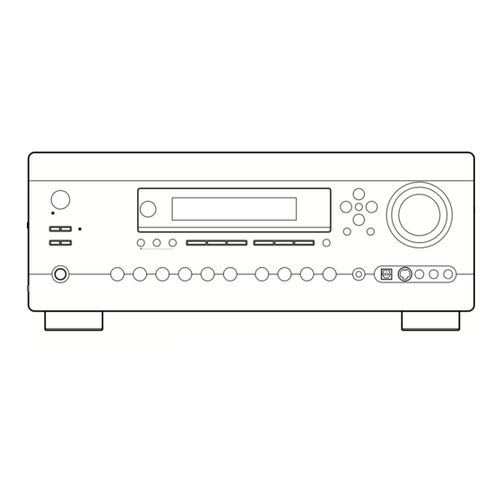
Page 8: Getting To Know The Av Receiver
Getting to Know the AV Receiver Front Panel 1 2 3 For detailed information, see the pages in parentheses. Standby/On button (37) Sets the AV receiver to On or Standby. Standby indicator (37) Lights up when the AV receiver is on Standby and flashes while a signal is being received from the remote controller. - Page 9 Getting to Know the AV Receiver—Continued Input selector buttons (46) Select the following input sources: Multi CH, DVD, Video 1, Video 2, Video 3, Video 4, Tape, Tuner, CD, or Phono. The [Multi CH] button selects the multichannel DVD input. Display For detailed information, see the pages in parentheses.
-
Page 10: Rear Panel
Getting to Know the AV Receiver—Continued Rear Panel P Q R S OPTICAL DIGITAL These optical digital audio inputs are for connecting components with optical digital audio outputs, such as CD players and DVD players. The optical digital audio output is for connecting a digital recorder with an optical digital input, such as a CD recorder. - Page 11 Getting to Know the AV Receiver—Continued REMOTE CONTROL This (Remote Interactive) jack can be con- nected to the jack on another gra/Onkyo component, for remote and system control. To use , you must make an analog audio connec- tion (RCA) between the AV receiver and the other component, even if they are connected digitally.
-
Page 12: Remote Controller
(see page 84). ■ CD Mode By default, you can control an Integra/Onkyo CD player in this mode. By entering the appropriate remote control code, you can control a CD player, MD recorder, or CD recorder made by another manufacturer (see page 84). - Page 13 Remote Controller—Continued For detailed information, see the pages in parentheses. Standby button (37) Sets the AV receiver to Standby. On button (37) Turns on the AV receiver. Input Selector buttons (46) Used to select the input sources. Multi CH button (53) Selects the multichannel DVD input.
- Page 14 Remote Controller—Continued DVD Mode To set the remote controller to DVD mode, press the [DVD] Remote Mode button. Standby button Sets the DVD player to Standby. On button Turns on the DVD player. Number buttons Used to enter title, chapter, and track numbers, and to enter times for locating specific points.
- Page 15 Remote Controller—Continued CD, MD, and CDR Modes To control an Integra/Onkyo CD player or an Onkyo CD/MD recorder made by another manufacturer, press the [CD] Remote Mode button to select the CD remote controller mode. To control an Onkyo MD recorder or CD recorder, press the [MD] or [CDR] Remote Mode button to select the MD or CDR remote controller mode.
- Page 16 Remote Controller—Continued HDD Mode HDD mode is for controlling Onkyo’s next generation HDD-compatible components. As of 2006, it can be used with the Onkyo RI Dock (Remote Interactive Dock) and Apple iPod connected via When Using the RI Dock: • Connect the RI Dock to the TAPE IN or VIDEO 3 IN jacks.
-
Page 17: Connecting Your Speakers
Connecting Your Speakers Enjoying Home Theater Thanks to the AV receiver’s superb capabilities, you can enjoy surround sound with a real sense of movement in your own home—just like being in a movie theater or concert hall. You can enjoy DVDs featuring DTS and Dolby Digital. With analog and digital TV, you can enjoy Dolby Pro Logic IIx and Onkyo’s own DSP surround listening modes. -
Page 18: Connecting A Powered Subwoofer
Connecting Your Speakers—Continued Connecting Your Speakers Speaker Configuration For the best surround-sound experience, you should con- nect seven speakers and a powered subwoofer. The following table shows which channels you should use based on the number of speakers you have. Number of speakers: ✓... - Page 19 Connecting Your Speakers—Continued Speaker Connection Precautions Read the following before connecting your speakers: • You can connect speakers with an impedance of between 4 and 16 ohms. If the impedance of any of the connected speakers is 4 ohms or more but less than 6, be sure to set the minimum speaker impedance to 4 ohms (see page 44).
-
Page 20: Connecting Antenna
Connecting Antenna This section explains how to connect the supplied indoor FM antenna and AM loop antenna, and how to connect commercially available outdoor FM and AM antennas. The AV receiver won’t pick up any radio signals without any antenna connected, so you must connect the antenna to use the tuner. -
Page 21: Connecting An Outdoor Fm Antenna
Connecting Antenna—Continued Connecting an Outdoor FM Antenna If you cannot achieve good reception with the supplied indoor FM antenna, try a commercially available out- door FM antenna instead. Notes: • Outdoor FM antennas work best outside, but usable results can sometimes be obtained when installed in an attic or loft. -
Page 22: Connecting Your Components
Connecting Your Components About AV Connections • Before making any AV connections, read the manuals supplied with your other AV components. • Don’t connect the power cord until you’ve completed and double-checked all AV connections. Optical Digital Jacks The AV receiver’s optical digital jacks have shutter-type covers that open when an optical plug is inserted and close when it’s removed. -
Page 23: Connecting Audio And Video Signals To The Av Receiver
Connecting Your Components—Continued Connecting Audio and Video Signals to the AV Receiver By connecting both the audio and video outputs of your DVD player and other AV components to the AV receiver, you can switch the audio and video signals simultaneously simply by changing the input source on the AV receiver. : Signal Flow Video Audio... -
Page 24: Tv Or Projector
Connecting Your Components—Continued Connecting a TV or Projector Step 1: Video Connection Choose a video connection that matches your TV ( , Step 2: Audio Connection Choose an audio connection that matches your TV ( , • With connection , you can listen to and record audio from your TV and listen in Zone 2. •... -
Page 25: Dvd Player
Connecting Your Components—Continued Connecting a DVD player Step 1: Video Connection Choose a video connection that matches your DVD player ( , If you use connection , you must connect the AV receiver to your TV with the same type of connection. Step 2: Audio Connection Choose an audio connection that matches your DVD player ( , •... - Page 26 Connecting Your Components—Continued Hooking Up the Multichannel DVD Input If your DVD player supports multichannel audio formats such as DVD-Audio or SACD, and it has a multichannel analog audio output, you can connect it to the AV receiver’s multichannel DVD input. Use a multichannel analog audio cable, or several normal audio cables, to connect the AV receiver’s DVD IN FRONT L/R, CENTER, SURROUND L/R, SURR BACK L/R, and SUBWOOFER jacks to the 7.1-channel analog audio output on your DVD player.
-
Page 27: Vcr Or Dvd Recorder For Playback
Connecting Your Components—Continued Connecting a VCR or DVD Recorder for Playback With this hookup, you can use your VCR’s tuner to listen to your favorite TV programs via the AV Hint! receiver, useful if your TV has no audio outputs. If you have two video recorders (e.g., a VCR and a DVD recorder), connect one recorder to the VIDEO 1 IN jacks, as shown here, and connect the other recorder to the VIDEO 2 IN jacks in the same way. -
Page 28: Vcr Or Dvd Recorder For Recording
Connecting Your Components—Continued Connecting a VCR or DVD Recorder for Recording If you have two video recorders (e.g., a VCR and a DVD recorder), connect one recorder to the VIDEO 1 OUT jacks, as shown here, and connect the other recorder to the VIDEO 2 OUT jacks in the same way. Step 1: Video Connection Choose a video connection that matches your VCR or DVD recorder ( video source to be recorded must be connected to the AV receiver via the same type of connection. -
Page 29: Video Source
Connecting Your Components—Continued Connecting a Satellite, Cable, Set-top box, or Other Video Source With this hookup, you can use your satellite or cable receiver to listen to your favorite TV programs Hint! via the AV receiver, useful if your TV has no audio outputs. Step 1: Video Connection Choose a video connection that matches the video source ( , If you use connection... -
Page 30: Components With Hdmi
Connecting Your Components—Continued Connecting Components with HDMI About HDMI Designed to meet the demands of digital TV, HDMI (High Definition Multimedia Interface) is a new digital interface standard for connecting TVs, projectors, DVD players, set-top boxes, and other video components. Until now, several separate video and audio cables have been required to connect AV components. -
Page 31: Making Hdmi Connections
Connecting Your Components—Continued Making HDMI Connections Step 1: Use HDMI cables to connect the AV receiver’s HDMI jacks to your HDMI-compatible DVD player, TV, projector, and so on. Step 2: Assign each HDMI IN to an input selector in the HDMI Video setup (see page 41). ■... -
Page 32: Camcorder, Games Console, Or Other Device
Connecting Your Components—Continued Connecting a Camcorder, Games Console, or Other Device Step 1: Video Connection Choose a video connection that matches the camcorder or console ( Step 2: Audio Connection Choose an audio connection that matches the camcorder or console ( Connection Video 4 Input S Video Video 4 Input Video... -
Page 33: Cd Player
Connecting Your Components—Continued Connecting a CD Player Step 1: Choose a connection that matches your CD player ( , COAXIAL IN 2 OPTICAL IN 3 Connect one or the other • With connection , you can listen to and record audio from the CD player and listen in Zone 2. •... -
Page 34: Cassette, Cdr, Minidisc, Or Dat Recorder
Connecting Your Components—Continued Connecting a Cassette, CDR, MiniDisc, or DAT Recorder Step 1: Choose a connection that matches the recorder ( , COAXIAL IN 2 OPTICAL IN 4 OPTICAL Connect one or the other • With connection , you can play and record and listen in Zone 2. •... -
Page 35: Hdd-Compatible Component
AC OUTLETS does not exceed the stated capacity (e.g., TOTAL 120 W). Note: • Integra/Onkyo components connected via connected directly to a wall outlet, not an AC OUTLET on the AV receiver. • The number of AC OUTLETS, socket type, and total capacity depends on the country in which you purchased the AV receiver. -
Page 36: Connecting Components
Connecting Your Components—Continued Connecting Components Step 1: Make sure that each Integra/Onkyo component is connected to the AV receiver with an analog audio cable (RCA). Step 2: Make the connection. Step 3: If you’re using an MD, CDR, or HDD component, change the Input Display (see page 44). -
Page 37: Turning On The Av Receiver
Turning On the AV Receiver Standby/On Standby indicator Turning On and Standby Press the [Standby/On] button. Remote Alternatively, press the remote controller’s [Receiver] button, followed by AV receiver controller the [On] button. The AV receiver comes on, the display lights up, and the Standby indicator goes off. Pressing the remote controller’s [On] button again will turn on any components con- nected via To turn the AV receiver off, press the [Standby/On] button, or press the remote control-... -
Page 38: First Time Setup
First Time Setup This section explains the settings that you need to make before using the AV receiver for the very first time. Automatic Speaker Setup With the supplied speaker setup microphone, the Auto- matic Speaker Setup function can measure the test tone output by each speaker and automatically determine the number of speakers connected, the crossover frequency, the distance from each speaker to the listening position,... - Page 39 First Time Setup—Continued Press [Enter]. The automatic speaker setup starts. The test tone is output by each speaker in turn. The microphone picks up the sound and feeds it back to the AV receiver, where it’s used to calculate the optimum speaker settings.
- Page 40 First Time Setup—Continued ■ Checking the Results If you selected “Check the Results” in step 4 on the pre- vious page, the following menu appears and you can check the results of the automatic speaker setup. Auto Speaker Setup ======================== 1.Warning 2.Speaker Config 3.Speaker Distance...
-
Page 41: Hdmi Video Setup
First Time Setup—Continued HDMI Video Setup If you connect a video component to HDMI IN 1 or 2, you must assign that input to an input selector. For exam- ple, if you connect your DVD player to HDMI IN 1, you must assign HDMI IN 1 to the DVD input selector. -
Page 42: Component Video Setup
First Time Setup—Continued Component Video Setup If you connect a video component to COMPONENT VIDEO IN 1, 2, or 3, you must assign that input to an input selector. For example, if you connect your DVD player to COMPONENT IN 3, you must assign COM- PONENT IN 3 to the DVD input selector. -
Page 43: Digital Audio Input Setup
First Time Setup—Continued Digital Audio Input Setup If you connect a component to a digital input, you must assign that input to an input selector. For example, if you connect your CD player to OPTICAL IN 2, you must assign OPTICAL IN 2 to the CD input selector. Here are the default assignments. -
Page 44: Changing The Input Display
First Time Setup—Continued Changing the Input Display If you connect an -capable Onkyo MiniDisc recorder, CD recorder, or next generation HDD-compat- ible component, such as the Remote Interactive Dock, to the TAPE IN/OUT or VIDEO 3 IN jacks, for work properly, you must change this setting. This setting can only be changed on the AV receiver. -
Page 45: Tv Format Setup (Not North American Models)
First Time Setup—Continued TV Format Setup (not North American models) You must specify the TV system used in your area. Press the [Receiver] button, fol- lowed by the [Setup] button. The main menu appears onscreen. Use the Up and Down [ buttons to select “8. -
Page 46: Basic Operation
Playing Your AV Components Basic AV Receiver Operation Remote controller AV receiver Remote controller AV receiver Use the AV receiver’s input selector buttons to select the input source. To select the input source with the remote controller, press the [Receiver] Remote Mode button, and then use the Input Selector buttons. -
Page 47: Listening To The Radio
Listening to the Radio Listening to AM/FM Stations Tuning Mode Tuner With the built-in tuner, you can enjoy AM and FM radio stations, and store your favorite stations as presets for easy selection. Use the [Tuner] input selector button to select AM or FM. In this example, FM has been selected. -
Page 48: Listening To Xm Satellite Radio
Listening to the Radio—Continued Listening to XM Satellite Radio (North American Models Only) Important XM Radio Information XM Satellite Radio offers an extraordinary variety of commercial-free music, plus the best in sports, news, talk and entertainment. XM is broadcast in superior digital audio from coast to coast. - Page 49 Listening to the Radio—Continued Connecting the XM Mini-Tuner and Home Dock To receive XM Satellite Radio, you need an XM Mini- Tuner and Home Dock, which includes a home antenna. These are sold separately. For connection information, refer to the instruction manual supplied with the XM Mini-Tuner and Home Dock.
- Page 50 Listening to the Radio—Continued Receiver Enter Display Selecting XM Radio Channels There are two ways to select XM radio channels: • Channel Search mode: select any channel. • Category Search mode: select channels by category. Note: You can’t select Channel Search or Category Search mode, while the Tuning Arrow flashing, as tuning is in progress.
- Page 51 Listening to the Radio—Continued Displaying XM Radio Information Press the [Display] button repeatedly to cycle through the available information. Channel name The following information is displayed: 1. Channel name 2. Channel number & Preset number 3. Category name (CAT) 4. Artist name (NAME) 5.
-
Page 52: Presetting Am, Fm, And Xm Stations
Listening to the Radio—Continued Presetting AM, FM, and XM Stations 2, 4 You can store a combination of up to 40 of your favorite AM, FM, and XM radio stations. Tune into the AM, FM, or XM sta- tion you want to store as a pre- set. -
Page 53: Using The Multichannel Dvd Input
Using the Multichannel DVD Input Multi CH Receiver Enter Using the Multichannel DVD Input The multichannel DVD input is for connecting a compo- nent with a 5.1/7.1-channel analog audio output, such as a DVD player, DVD-Audio/SACD-capable player, or an MPEG decoder. See page 26 for hookup information. Press the [Receiver] Remote Mode button, followed by the [Multi CH] button. -
Page 54: Common Functions
Common Functions This section explains functions that can be used with any input source. Press [Receiver] first Dimmer Display CH Sel Phones Dimmer Setting the Display Brightness You can adjust the brightness of the display. Press the [Dimmer] button Remote controller repeatedly to select: Normal, Dim, Dimmer. -
Page 55: Using The Sleep Timer
Common Functions—Continued Using the Sleep Timer With the sleep timer, you can set the AV receiver so that it turns off automatically after a specified period. Press the remote controller’s [Sleep] button repeatedly to select the required sleep time. You can set the sleep time from 90 to 10 minutes in 10 minute steps. -
Page 56: Using The Listening Modes
Using the Listening Modes Selecting the Listening Modes For a description of each listening mode, see “About the Listening Modes” on page 58. • The Dolby Digital and DTS listening modes can only be selected if your DVD player is connected to the AV receiver with a digital audio connection (coaxial, optical, or HDMI). - Page 57 Using the Listening Modes—Continued The following table shows which listening modes can be used with each input signal format. Source format Analog, CD, TV, radio, cassette, Listening mode etc. Direct ✔ Stereo ✔ Mono Multich PLIIx Movie/Music/Game ✔ Neo:6 Cinema Neo:6 Music Dolby D Dolby D EX...
-
Page 58: About The Listening Modes
Using the Listening Modes—Continued About the Listening Modes The AV receiver’s listening modes can transform your listening room into a movie theater or concert hall, with high fidelity and stunning surround sound. Direct In this mode, audio from the input source is output directly with minimal processing, providing high-fidel- ity reproduction. - Page 59 Using the Listening Modes—Continued Founded by George Lucas, THX develops stringent stan- dards that ensure movies are reproduced in movie the- aters and home theaters just as the director intended. • THX Cinema This mode is for watching movies, which are typi- cally recorded and edited on the assumption that they will be played in a sizable place like a movie theater.
-
Page 60: Recording
Recording This section explains how to record the input source and how to record audio and video from separate sources. Notes: • The surround sound and DSP listening modes cannot be recorded. • Copy-protected DVDs cannot be recorded. • Sources connected to the multichannel DVD input cannot be recorded. -
Page 61: Onscreen Setup Menus
Onscreen Setup Menus About the Onscreen Setup Menus The onscreen setup menus are displayed on the connected TV (not via the HDMI OUT) and provide a convenient way to change the AV receiver’s settings, which are arranged into two groups: First Time Setup and Advanced Setup. To get your system up and running, you must complete the First Time Setup settings. -
Page 62: Adjusting The Listening Modes
Adjusting the Listening Modes Receiver Enter Using the Re-EQ Function With the Re-EQ function, you can correct a soundtrack whose high-frequency content is too harsh, making it more suitable for home theater viewing. This function can be used with the following listening modes: Dolby Digital, Dolby Digital EX, Dolby Pro Logic II Movie, Dolby Pro Logic IIx Movie, DTS, DTS- ES, DTS Neo:6 Cinema, DTS 96/24, THX Cinema,... -
Page 63: Tone Control Settings
Adjusting the Listening Modes—Continued Tone Control Settings You can adjust the bass and treble for the front speakers. The tone control circuits are bypassed in the Direct lis- tening mode. ■ Bass You can boost or cut low-frequency sounds output by the front speakers from –10 dB to +10 dB in 1 dB steps. - Page 64 Adjusting the Listening Modes—Continued Dolby Digital Settings ■ Dolby EX This setting determines how Dolby Digital EX signals are handled. This setting is unavailable if no surround back speakers are connected or the ZONE 2 SPEAKERS terminals are being used (page 78). Auto: Dolby Digital EX can be selected from among the Dolby listening modes, and THX Surround EX can be selected from among the...
-
Page 65: Default Listening Modes
Adjusting the Listening Modes—Continued Default Listening Modes You can specify a default listening mode for each signal format supported by each input selector. The AV receiver will then automatically select that listening mode based on the format of the input signal. You can select other listening modes while listening to a source, but the default listening mode specified here will be used next time you turn on the AV receiver. -
Page 66: Advanced Setup
Advanced Setup Speaker Setup This section explains how to check the speaker settings and how to set them manually, which is useful if you change a speaker after performing the automatic speaker setup. Some speaker settings are set automatically by the Auto- matic Speaker Setup function (see page 38). -
Page 67: Subwoofer Mode
Advanced Setup—Continued Use the Up and Down [ buttons to select “d. Surround,” and then use the Left and Right ] buttons to select a crossover frequency. If no surround left and right speakers are connected, select None. Note: • If the Front setting in step 5 is set to anything other than Full Band, Full Band cannot be selected here. -
Page 68: Speaker Distance
Advanced Setup—Continued Speaker Distance These settings are set automatically by the Automatic Speaker Setup function (see page 38). With these settings, you can specify the distance from each speaker to the listening position. Press the [Receiver] Remote Mode button, followed by the [Setup] button. - Page 69 Advanced Setup—Continued Speaker Level Calibration These settings are set automatically by the Automatic Speaker Setup function (see page 38). With these settings, you can adjust the level of each speaker while listening to the test tone so that the volume of each speaker is the same at the listening position.
-
Page 70: Thx Audio Setup
Advanced Setup—Continued THX Audio Setup This setting is not set automatically by the Automatic Speaker Setup function (see page 38). This setting is only available if the SurrBack Ch setting in the Speaker Configuration is set to 2ch. With this setting, you can specify the distance between your surround back speakers. - Page 71 Advanced Setup—Continued Equalizer Settings These settings are set automatically by the Automatic Speaker Setup function (see page 38). With these settings, you can adjust the tone of each speaker. The volume of each speaker can be set on page 69. Press the [Receiver] Remote Mode button, followed by the [Setup] button.
-
Page 72: Input Setup
Advanced Setup—Continued Input Setup This section explains items on the “Input Setup” menu. Character Edit With this setting, you can enter a custom name for each input source and AM/FM radio preset. When the input source or radio preset is selected, its name will appear on the display. -
Page 73: Preferences
Advanced Setup—Continued Preferences This section explains items on the “Preference” menu. Receiver Enter Press the [Receiver] Remote Mode button, followed by the [Setup] button. The main menu appears onscreen. Use the Up and Down [ buttons to select “7. Preference,” and then press [Enter]. - Page 74 Advanced Setup—Continued ■ Power On Vol / Z2 Power On Vol With these preferences, you can specify the volume set- tings to be used in the main room and Zone 2 when the AV receiver is turned on. When the Volume Display preference is set to Absolute, the range of “Power On Vol”...
-
Page 75: Remote Ids
Receiver Enter Changing the AV Receiver’s Remote ID When several Integra/Onkyo components are used in the same room, their remote ID codes may overlap. To dif- ferentiate the AV receiver from the other components, you can change its remote ID from 1, the default, to 2 or Note: If you change the AV receiver’s remote ID, be sure to set... -
Page 76: Digital Input Signal Formats
Advanced Setup—Continued Digital Input Signal Formats Normally, the AV receiver detects the signal format auto- matically. However, if you experience either of the fol- lowing issues when playing PCM or DTS material, you can specify the signal format as either PCM or DTS: •... -
Page 77: Correcting Sound And Picture Sync
Advanced Setup—Continued Correcting Sound and Picture Sync When using progressive scanning on your DVD player, you may find that the picture and sound are out of sync. With this setting, you can correct this by delaying the audio signals. You can set it from 0 to 250 milliseconds (ms) in 1 millisecond steps. -
Page 78: Zone 2
Zone 2 Connecting Zone 2 With the Zone 2 function, you can enjoy one input source in the main room and a different input source in another room. There are two ways to hook up your Zone 2 speakers: 1) Use another amp (receiver, integrated amp, or power amp) in Zone 2 and connect your Zone 2 speakers to it. -
Page 79: Powered Zone 2 Setting
Zone 2—Continued Powered Zone 2 Setting If you’ve connected your Zone 2 speakers to this AV receiver, as explained in “Using Only Speakers in Zone 2” on page 78, you must set the Powered Zone 2 setting to Act (Activated) as explained here. Press the [Receiver] Remote Mode button, followed by the [Setup] button. -
Page 80: Using Zone 2
Zone 2—Continued Using Zone 2 This section explains how to turn Zone 2 on and off, how to select an input source for Zone 2, and how to adjust the volume for Zone 2. Controlling Zone 2 from the AV Receiver To turn on Zone 2 and select an input source, press the [Zone 2] button repeatedly. - Page 81 Zone 2—Continued Adjusting the Volume for Zone 2 Zone 2 Level On the remote controller, press the [Zone 2] Remote Mode but- ton, and then use the [Level–] and [Level+] buttons. On the AV receiver, use the AV receiver Zone 2 Level [ The volume can be set to –∞...
-
Page 82: Using The 12V Triggers In Zone 2 And The Main Room
Zone 2—Continued Using the 12V Triggers in Zone 2 and the Main Room When the AV receiver’s 12 V TRIGGER OUT A/B/C jack is connected to the 12 V trigger input on a con- nected component, you can specify whether or not a 12- volt trigger signal is output when that component is selected as the source for the main room, Zone 2, or either. -
Page 83: Using The Remote Controller In Zone 2 And Multiroom Control Kits
Zone 2—Continued Using the Remote Controller in Zone 2 and Multiroom Control Kits To control the AV receiver with the remote controller while you’re in the Zone 2 room, you’ll need a commer- cially available multiroom remote control kit. • Multiroom kits are made by Niles and Xantech. These kits can also be used when there isn’t a clear line of sight to the AV receiver’s remote sensor, such as when it’s installed inside a cabinet. -
Page 84: Controlling Other Components
• The HDD remote mode can only be used with the Onkyo Remote Interactive Dock at this time. • The [DVD] and [CD] Remote Mode buttons are preprogrammed for use with Integra/Onkyo DVD players and CD players respectively. * To control another manufacturer’s CD recorder or MD recorder, enter the appropriate control code to the [CD] Remote Mode button. -
Page 85: Resetting The Remote Controller
Press the Remote Mode button, point the remote controller at the AV receiver, and operate the component. If you want to control an Integra/Onkyo component by pointing the remote controller directly at it, or you want to control an Integra/Onkyo component that’s not con-... - Page 86 Controlling Other Components—Continued To control another component, point the remote controller at it and use the buttons explained below. (You must select the appropriate remote control mode first.) With some AV components, certain buttons may not work as expected, and some may not work at all. ■...
-
Page 87: Learning Commands From Other Remote Controllers
• Remote controller buttons such as Play, Stop, Pause, and so on are preprogrammed with commands for controlling Integra/Onkyo CD players, cassette decks, and DVD players. However, they can learn new com- mands, and you can restore the preprogrammed com- mands by resetting the remote controller (see page 85). -
Page 88: Using Macros
Controlling Other Components—Continued Using Macros You can program the remote controller’s Macro buttons to perform a sequence of actions. Example: To play a CD, you typically need to perform the follow- ing actions: 1. Press the [Receiver] Remote Mode button to select the Receiver remote controller mode. -
Page 89: Troubleshooting
Troubleshooting If you have any trouble using the AV receiver, look for a solution in this section. If you can’t resolve the issue yourself, contact the dealer from whom you purchased. Power Can’t turn on the AV receiver • Make sure that the power cord is plugged into the wall outlet properly. - Page 90 Troubleshooting—Continued The subwoofer produces no sound • When you play source material that contains no infor- mation in the LFE channel, the subwoofer produces no sound. • Make sure the speakers are configured correctly (pages 66, 67). The Zone 2 speakers produce no sound •...
- Page 91 , point the remote controller at the AV receiver. Be sure to enter the appropriate remote con- trol code first (page 85). • To control an Integra/Onkyo component that’s not con- nected via , or another manufacturer’s component, point the remote controller at the component. Be sure to enter the appropriate remote control code first...
- Page 92 Troubleshooting—Continued The AV receiver contains a microcomputer for signal pro- cessing and control functions. In very rare situations, severe interference, noise from an external source, or static electricity may cause it to lockup. In the unlikely event that this happens, unplug the power cord from the wall outlet, wait at least five seconds, and then plug it back in again.
-
Page 93: Specification
Specification Amplifier Section Rated Power Output North American: 105 watts minimum continuous power per channel, 8 ohm loads, 2 channels driven from 20 Hz to 20 kHz, with a maximum total harmonic distortion of 0.08% (FTC) 135 watts minimum continuous power per channel, 6 ohm loads, 2 channels driven at 1 kHz, with a maximum total harmonic distortion of 0.1% (FTC) Australian:... - Page 94 Memo...
- Page 95 Memo...
- Page 96 Integra Division of ONKYO U.S.A. CORPORATION 18 park Way, Upper Saddle River, N.J. 07458, U.S.A. Tel: 201-785-2600 Fax: 201-785-2650 http://www.integrahometheater.com Integra Division of ONKYO CORPORATION I0609-2 Sales & Product Planning Div.: 2-1, Nisshin-cho, Neyagawa-shi, OSAKA 572-8540, JAPAN Tel: 072-831-8023 Fax: 072-831-8124 SN 29344337A (C) Copyright 2006 ONKYO CORPORATION Japan.