Table of Contents
Advertisement
Advertisement
Table of Contents

Related Manuals for Tokyo Hy-Power HL-2.5KFX


Summary of Contents for Tokyo Hy-Power HL-2.5KFX
- Page 1 INSTRUCTION MANUAL HF LINEAR POWER AMPLIFIER MODEL : HL-2.5KFX...
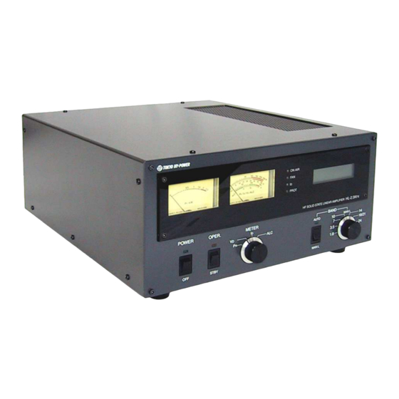
- Page 2 1. Introduction Thank you for purchasing the HL-2.5KFX. This compact and lightweight desktop HF linear power amplifier has a maximum input power of 2.9 kW. Our solid-state broadband power amp technology makes it the smallest and lightest in the industry.
- Page 3 inserted at both ends of the remote control cable, ALC cable, coaxial jumper cable, and antenna cables, as needed. Also, a common mode AC line filter (near the AC outlet), and in-line low pass filters on the antenna coaxial cable, (as necessary), are recommended.
- Page 4 MUST be shipped using the original box and packaging materials. 3. Features Our solid-state broadband design engineers worked to make the HL-2.5KFX, the lightest and most compact 1.5 kW HF amplifier in the industry. This world-class compact 1.5 kW HF amplifier is the easiest to handle and operate.
- Page 5 Vd (Drain voltage of power FET), Id (Drain current) and ALC voltage. 3-10 For future expansion, the amplifier rear panel is equipped with a control cable connection socket, this is for the upcoming model HC-1.5KAT, auto antenna tuner by Tokyo Hy-Power Labs. in 2007.
-
Page 6: Specifications
4. Specifications Frequency 1.8 ~ 28 MHz all amateur bands including WARC bands Mode SSB, CW, RTTY RF Drive 85W typ. (100W max.) Output Power 1.5 kW PEP/CW (typ.) (1.2 kW on 28 MHz band) Matching Transceivers for Auto Band Decoder Most ICOM, Yaesu, Kenwood Drain Voltage 120 V (when no RF drive) -
Page 7: Ac Line Voltage
Instruction Manual x 1 Optional Items Auto Antenna Tuner (HC-1.5KAT) 5. AC Line Voltage The amplifier is designed to work with AC 240 V (200- 250 V). The correct AC plug (not included in the package), must be obtained locally due to the AC plug variations worldwide. The AC voltage has been factory preset for 240 V use (or as requested by the customer at the time of order). -
Page 8: A Front Panel Description
Front Panel Description ‡ E ‡ F ‡ ‡ H ‡ @ ‡ ‡ ‡ ‡ ‡ @ POWER Main power switch to turn AC power on and off. LED (green) lights when turned on. ‡ A OPER. OPERATE/STAND-BY switch. At OPERATE, the amplifier is ready to go into ON AIR (TX) mode and at STBY, it is on STAND-BY mode. - Page 9 MULTIMETER (Reflected power from antenna), V (FET drain voltage), and I (FET drain current) and ALC voltage are shown on the scale as selected by ‡ B METER select switch. Full scales are; P :250 W, V : 150 V, I : 40 A, ALC: -10V.
-
Page 10: B Rear Panel Description
Rear Panel Description ‡ B ‡ C ‡ A ‡ @ ‡ D ‡ F ‡ G ‡ H ‡ E ‡ I ‡ J ‡ K ‡ L ‡ @ ANT A RF Output Connector. Connect the coax cable to the antenna. ‡... -
Page 11: Top View
Factory setting is 0 volts, with the pot turned full clockwise. (See page 16, Section 9. ALC Connection for more details.) ‡ J ALC RCA Jack for ALC Voltage Output. Negative DC voltage appears at the center pin, which is fed back to the ALC terminal of the transceiver. - Page 12 STBY ALC ANT • • • • • • • • 230V AC Cord PTT Cable ALC Cable Coax Jumper Cable Connector and Cable List HL-2.5KFX side Signal Description Display/ Cable side connector name Connector ACIN IEC3P ‡ @ AC200L...
- Page 13 Technical Information Equivalent Circuit of SEND Terminal Equivalent Circuit of ALC Output...
-
Page 14: Operation
8. Operation ***CAUTION: Under the Manual Band Set operation, always be sure to check if BAND Switch position matches that of your radio before keying PTT or the CW paddle. Also when you have changed the BAND, do not make the full power CW (carrier) drive but reduced level power to see if the BAND is set correctly and the amplified RF power comes out properly. - Page 15 How to Operate 8-2-1 Connect AC cord and coax cables as illustrated in Section 7 Connection. Connect the cable from “SEND” to ACC or the remote terminals of transceiver, where it is marked “SEND” or “TX GND”. These terminal pins are shorted to ground when the transceiver is in TX/ON AIR mode.
-
Page 16: Alc Connection
8-2-5 You can now increase the drive level to nearly 80-90W to achieve maximum carrier output power of 1.4 kW (CW, RTTY) from the amplifier. If you change to SSB mode, peak voice power will reach approximately 1.5 kW. For high duty cycle transmissions like RTTY, SSTV, or FM modes, it is recommended you reduce the drive power by 20-30 % compared with SSB/CW. - Page 17 always need to connect ALC to the transceiver, if you set the mic gain properly and do not overdrive the amplifier. Depending upon the manufacturer of the transceiver, the suitable ALC voltage differs. ICOM may need 0~-4 V, and Yaesu may need 0~-5 V range..
-
Page 18: Band Data Cable Connection
Be sure to confirm the auto band set on each band, after you finish above settings. Manual Band set CONT SELECT Auto Band set/ CI-V 10-1 ICOM DC Voltage Band Data ‡ @ HL-2.5KFX Setting TRX ACC SELECT: “I” 3.5mm PHONE PLUG LCD: “ICOM” Wiring: Fig. A ‡... - Page 19 9600 [bps] CI-V ADDRESS: 5 Ch CI-V Transceiver: <Fig. B> CI-V with IC-731: (See ICOM radio manual for the details.) 10-3 Yaesu Band Data ‡ @ HL-2.5KFX Setting TRX ACC SELECT: “Y” LCD: “YSU” BAND-A Wiring: Fig. C BAND-B BAND-C BAND-D ‡...
- Page 20 11-1 otection Circuits HL-2.5KFX is equipped with ten protection circuits as shown in the table below. Protections are commanded by the 16bit microprocessor chip, and DC drain voltage (120 V) is cut off, when the protection circuit works. Also PROT lamp is lit nd the amplifier becomes “th...
- Page 21 11-2 Safety Circuits In addition to the protection circuits above, there are other safety circuits (inter-locked circuits) built in th e amplifier. They directly shut down AC power line for the primary of the power transformer, and if shut down, AC power lamp (green), LCD display and cooling fan will all go off.