Table of Contents
Advertisement
Quick Links
See also:
User Manual
Advertisement
Table of Contents

Related Manuals for Honeywell HCC334L


Summary of Contents for Honeywell HCC334L
-
Page 1: Color Camera
Color Camera Document G-113077-001 – 02/07 – Rev 3 L-Series NTSC HCC334L HCC484L User Guide HCC334LX HCC484LX HCC335LX HCC485LX... - Page 2 Revisions Issue Date 1.00 06/06 1.01 08/06 02/07 Rev 3 Revisions New document Added 230V (HCC335LX, HCC485LX). Updated document part no.; added warning to p. iii. G-113077-001 02/07...
-
Page 3: Explanation Of Graphical Symbols
Warnings Installation and servicing should be performed only by qualified and experienced personnel to conform to all local codes and to maintain your warranty. WARNING! 12 VDC/24 VAC models require the use of CSA Certified/UL Listed Class 2 power adapters to ensure compliance with electrical safety standards. -
Page 4: Fcc Compliance Statement
FCC Compliance Statement Information to the User: This equipment has been tested and found to comply with the limits for a Class A digital device. Pursuant to Part 15 of the FCC Rules, these limits are designed to provide reasonable protection against harmful interference when the equipment is operated in a commercial environment. -
Page 5: Table Of Contents
Contents Introduction ....... 1 Features ....... . 1 Before You Begin . -
Page 6: Introduction
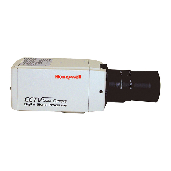
Introduction The Honeywell L-Series Color cameras are ideally suited for use in day-to-day surveillance applications. The L- Series cameras are designed for exceptional value and performance for everyday use. Their off-the-shelf feature set is designed for high picture quality in standard applications and they require little to no adjustment after installation. -
Page 7: Before You Begin
Before You Begin Please read this guide carefully before you install the L-Series Color camera. Keep this guide for future reference. Unpack Everything Check that the items received match those listed on the order form and packing slip. The L-Series packing box should include, in addition to this User Guide: •... -
Page 8: Camera Settings
Camera Settings Camera Functions Figure 2 Low Voltage (HCC334L/X, HCC484L/X) P U S H IR IS L E V E L V-P H L O C K P W R D C 12V G N D A C 24V Legend... -
Page 9: Setting Up Your Camera
Setting Up Your Camera Figure 3 shows the factory set DIP switch settings. Automatic Gain Control (AGC) and Auto White Balance Control (AWC) are set ON. Figure 3 IRIS LEVEL PUSH IRIS LOCK LEVEL V-PH DC 12V AC 24V Selecting the Lens Manual Lens Set the EE/ME DIP switch on the rear of the camera (see Figure... -
Page 10: Video Drive (Vsd) Lens
Slowly turn the LEVEL potentiometer until the picture on the monitor is as clear as possible and is not too bright. Video Drive (VSD) Lens Set the VSD/DC switch on the rear of the camera (see Figure 3) to VSD. Exposure Mode Automatic Exposure Mode The Electronic Exposure feature compensates for... -
Page 11: Backlight Compensation (Blc)
Backlight Compensation (BLC) If there is excessive light (for example, a window exists in a scene), the camera tries to compensate by reducing the overall exposure, resulting in the areas surrounding the window becoming too dark. Turn the BLC switch ON to eliminate the silhouette effect. -
Page 12: Auto White Balance Control (Awc)
Auto White Balance Control (AWC) This mode covers a wider range of 2000°K to 10000°K and performs at a faster operating speed than ATW mode. This mode is typically used for outdoor applications or where variable lighting conditions exist. One Push Lock Press PUSH LOCK on the rear of the camera to calibrate the white balance for the current scene. -
Page 13: Line Lock Phase Adjustment Potentiometer
Line Lock Phase Adjustment Potentiometer When the camera is in Line lock mode, it is possible to adjust the point on the AC cycle at which the camera triggers. This feature allows for synchronization of cameras that are connected to different phases. The V-PHASE adjustment potentiometer allows the line lock phase trigger point to be adjusted by 270°. -
Page 14: Lens Installation
Lens Installation Adjusting the Back Focus The back focus adjustment is accessible at the front end of the camera housing to adjust the back focal length or picture focus. The range of adjustment allows both C- and CS-mount lenses to be used without the need for a spacer ring. Figure 4 Loosen the setscrew with a Phillips screwdriver. - Page 15 Figure 5 DC (Direct Drive) lens CTRL - CTRL + DRV + DRV - Set the select switch to DC Rev 3 DC and VSD Lens Pin Definition Auto Iris lens connector Video (VSD) lens Power (+12V) Video Signal Set the select switch to VSD G-113077-001 02/07...
-
Page 16: Completing The Installation
Completing the Installation Mounting the Camera Mounting points are provided on the top of the camera for mounting the camera on a bracket or tripod. They are designed to accept standard sized 1/4 x 20 mounting screws. This bracket can be unscrewed and mounted onto the opposite side of the camera, depending on your application. -
Page 17: Connecting The Camera
Connect the camera to a power supply appropriate for your installation. HCC334L/X, HCC484L/LX: 12 VDC or 24 VAC power supply HCC335LX, HCC485LX: 230V power supply Plug in the power supply. The power (PWR) LED illuminates to show that the camera is receiving power. -
Page 18: Warranty And Service
Prior authorization must be obtained for all returns, exchanges, or credits. Items shipped to Honeywell without a clearly identified Return Merchandise Authorization (RMA) number may be refused. Specifications Note These specifications refer to all models, except where otherwise noted. HCC334L Operational Image Sensor: Video NTSC Standard: Scanning 525 lines,... - Page 19 Gamma: Electrical Input Voltage: HCC334L/LX, HCC484L/LX: 12 VDC/24 VAC HCC335LX, HCC485LX: 230 VAC Input Voltage HCC334L/LX, HCC484L/LX: 11 - 16 VDC, 17 - 28 VAC Range: HCC335LX, HCC485LX: 230 VAC ± 10% Power HCC334L/LX, HCC484L/LX: 3.5 W Consumption: HCC335LX, HCC485LX: 4.2 W (max)
- Page 20 Honeywell Video Systems (Head office) 2700 Blankenbaker Pkwy, Suite 150 Louisville, KY 40299, USA www.honeywellvideo.com ℡ +1.800.796.2288 Honeywell Security Australia Pty Ltd. Unit 5, Riverside Centre 24-28 River Road West Parramatta, NSW 2150, Australia www.ademco.com.au ℡ +61.2.8837.9300 Honeywell Security Asia Pacific 33/F Tower A, City Center, 100 Zun Yi Road Shanghai 200051, China...