Omron OS32C Series User Manual
Safety laser scanner
Hide thumbs
Also See for OS32C Series:
- Quick reference manual (2 pages) ,
- Quick start manual (7 pages)

Related Manuals for Omron OS32C Series


Summary of Contents for Omron OS32C Series
- Page 1 Safety Laser Scanner OS32C Series User's Manual OSTI P/N 99863-0010 Rev.H Manual No. Z296-E1-08...
-
Page 3: Legislation And Standards
Legislation and Standards 1. Application of an OS32C sensor by itself cannot receive the type approval provided by Article 44-2 of the Labor Safety and Health Law of Japan. It is necessary to apply it as a system. Therefore, when using this product in Japan as a "safety system for presses and shearing machines"... -
Page 4: Terms And Conditions Agreement
(a) Exclusive Warranty. Omron's exclusive warranty is that the Products will be free from defects in materials and workmanship for a period of twelve months from the date of sale by Omron (or such other period expressed in writing by Omron). Omron disclaims all other warranties, express or implied. - Page 5 Performance Data. Data presented in Omron Company websites, catalogs and other materials is provided as a guide for the user in determining suitability and does not constitute a warranty. It may represent the result of Omron's test conditions, and the user must correlate it to actual application requirements.
-
Page 6: Safety Precautions
Safety Precautions The Alert symbols and their meanings ensure safe use of the products In order to use the OS32C safely, the precautions listed in this manual are indicated by alert symbols. The descriptions must be followed, failure to follow all precautions and alerts may result in an unsafe installation or operation. - Page 7 The machine requirements The guarded machine must be able to stop anywhere in its cycle. Do not use an OS32C on a press with a full-revolution clutch. The guarded machine must have a consistent stopping time and adequate control mechanisms. All safety-related machine control elements must be designed so that an alarm in the control logic or failure of the control circuit does not lead to a failure to danger.
- Page 8 To use the protective function of the OS32C, a safety zone must be properly defined and configured. If the response time is changed, re-calculation of the safety distance is required. This may require re-configuration of the safety zones or re-installation of the OS32C. If the safety distance is not appropriate for the application, the machine may not stop before contact with the hazardous part, resulting in serious injuries or death.
- Page 9 Wiring Connections Do not connect the OS32C to a power supply with more than 24VDC + 25% / -30%. Do not supply AC power to the OS32C, this may result in electrical shock. For the OS32C to meet IEC 61496-1 and UL 508, its DC power supply unit must satisfy all of the following conditions: •Within rated line voltage (24 VDC +25% / -30%) •Complying with EMC directives (industrial environments)
- Page 10 Others Do not modify the main unit of the OS32C. Do not replace or fix any component of the OS32C other than the ones specified in this manual. Doing so may result in a failure of this device to function correctly. If there is any damage to the window, replace them as soon as possible.
- Page 11 When transferring data from the PC to the OS32C and more than one OS32C is connected to the network, it is necessary to visually check the diagnostic code on the status/diagnostic display. It is recommended that the OS32C be installed in a position where the status/diagnostic display will be visible.
-
Page 12: Precautions For Safe Use
Precautions for Safe Use Make sure to follow all the safety precautions that are necessary to ensure safe use of the product. • Thoroughly read this installation manual and understand the installation, operation checks, and maintenance procedures before using the product. •... - Page 13 Cleaning Do not use thinner, benzene, or acetone for cleaning. They will adversely affect the product's resin parts and paint on the case. Object detection The OS32C has a configurable minimum object resolution of 30mm, 40mm, 50mm, or 70mm. It cannot detect transparent or translucent objects, or objects with reflective surfaces, of less than 1.8% reflectivity.
-
Page 14: How To Read This Manual (Explanation Of Symbols)
How to Read This Manual (Explanation of Symbols) Indicates the description of an essential function, such as operation or advice on how to properly use this product . Indicates the page number for related content. OS32C User’s Manual... -
Page 15: Firmware And Configuration Tool Features And Compatibility
Please refer to the table below for supported features and compatibility with OS32C versions. Refer to the product labels to determine the OS32C version. For information on the OS32C-DM model, please refer to the OS32C-DM Addendum available on the Omron STI website at www.sti.com NOTE: •... - Page 16 EtherNet/IP and Measurement Data Supported *1. Requires Configuration Tool Version 1.4.0 and up *2. Requires Configuration Tool Version 1.6.0 and up *3. If serial number of the sensor block is higher than AS08300 and Configuration Tool is version 1.6.0 and up *4.
-
Page 17: Table Of Contents
Contents Legislation and Standards Terms and Conditions Agreement Safety Precautions Precautions for Safe Use Precautions for Correct Use How to Read This Manual (Explanation of Symbols) Firmware and Configuration Tool Features and Compatibility xiii Chapter1 Description of Use and Features Theory of Operation Features System Components... - Page 18 Description of Screen Menu Tool Bars Information Bar Offline Mode Connection to the OS32C Connecting the PC and the OS32C Forced DHCP mode Changing the IP address of the PC (Windows 2000) Changing the IP address of the PC (Windows XP) Changing the IP address of the PC (Windows Vista) Changing the IP address of the PC (Windows 7) Logging on to the OS32C...
- Page 19 Applying OS32C on Automated Guided Vehicles (AGV) Configuration for Automated Guided Vehicles (AGV) Configuration Example: Use of an AGV AGV Standards External Dimensional Drawings Ethernet Cable XS5 OMRON Smartclick Connection Chapter5 Wiring Power Supply Unit Additional Wiring Information Input/Output Signal...
- Page 20 Scan Window Replacement Procedure Window Replacement Procedure OS32C Maintenance Additional Zone Set Switching Strategies Glossary Accessories Checkout and Test Procedure Log Declaration of Conformity Revision History OS32C xviii User’s Manual...
-
Page 21: Chapter1 Description Of Use And Features
Chapter1 Description of Use and Features Theory of Operation Features System Components Application Examples Applying the OS32C to fixed stationary applications Applying the OS32C on Automated Guided Vehicles (AGV) 7 Rating/Performance OS32C User’s Manual... -
Page 22: Theory Of Operation
Description of Use and Features Theory of Operation The OS32C safety laser scanner is an optical safety sensor that uses diffuse reflection of a pulsed laser light to determine the location of objects entering a predefined monitoring zone. Internally, a spinning mirror assembly scans a monitoring zone by sending a pulse of light which reflects off the first object in its path. -
Page 23: Features
Description of Use and Features Features • Can detect intrusions within the safety zone with a radius of up to 3m (min. obj. resolution of 50mm or 70mm) and two warning zones with a radius of 10m, covering a maximum scan angle of 270°. •... -
Page 24: System Components
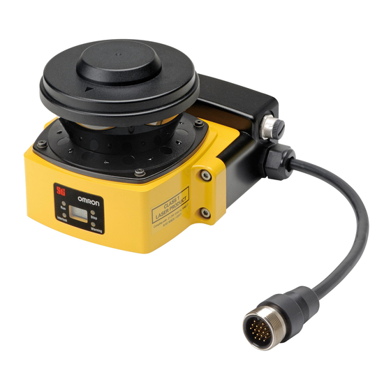
Description of Use and Features System Components (10) (11) (12) (13) Fig. 1-1 System Components Number Component Function RUN indicator (green) Will turn ON when safety zone is clear and OSSDs are ON. Interlock Indicator (yellow) Will turn ON when in interlock state, blink under lockout, and blink in case of a failure. Status/Diagnostic Display The scanner's status ,configuration/operation, or failure is displayed Warning Output Indicator... -
Page 25: Application Examples
Description of Use and Features Application Examples The OS32C may be used for personnel safeguarding. Typical applications include work cell area guarding and collision prevention of AGV (Automated Guided Vehicles). The OS32C is a versatile Safety Laser Scanner capable of guarding many types of applications. The application examples in this chapter are for informational and instructional purposes only and not intended to represent complete guarding solutions. - Page 26 Description of Use and Features Fig. 1-4 Internal Robot Cell Guarding In this application the OS32C is the secondary guarding device in conjunction with a safety light curtain. The OS32C is responsible for detecting that the work area is clear before start-up of the robot occurs.
-
Page 27: Applying The Os32C On Automated Guided Vehicles (Agv)
Description of Use and Features Zone-1 Zone-1 Zone-2 Zone-2 Fig. 1-6 Dual Zone Vertical Guarding In this application the OS32C is the primary guarding device, using a vertical protective field for entry presence detection. The OS32C can guard the hazardous area based on the robot’s position. When the robot is in the left side, the OS32C guards the left side and changes to the right side along with the robot. - Page 28 Description of Use and Features Fig. 1-8 Automated Guided Vehicles, Bi-directional (AGV) In this application two OS32Cs are the primary guarding devices. The two warning fields of the OS32C are used to give personnel extra warning, allowing them to move out of the AGV path. This is essential in achieving maximum travel efficiency.
- Page 29 Description of Use and Features Fig. 1-10 Automated Guided Vehicles (AGV), Two Scanners, Three Sided In this application two OS32Cs are used as the primary guarding devices, using 270 degree protective fields. They are positioned at the front corners, this scheme allows for two scanners to guard three sides of the AGV.
-
Page 30: Rating/Performance
Description of Use and Features Rating/Performance Sensor Type Type 3 Safety Laser Scanner Safety Category Category 3, Performance Level d (ISO13849-1: 2008) Functional Safety of SIL 2 (IEC61508) Electrical/Electronic/ Programmable Electronic Safety-related Systems Detection Capability Configurable; Non-transparent with a diameter of 30, 40, 50, 70mm (1.8% reflectivity or greater) Monitoring Zone Monitoring Zone Set Count (Safety Zone + 2 Warning Zones) : 70 sets max. - Page 31 Description of Use and Features Ambient Humidity Operation & Storage: 95%RH max., non-condensing Ambient Operation Incandescent lamp: Illumination on receiving surface 1500lx max. (an angle of laser scanning plane and Illumination disturbance light must be +/-5 degrees or more) Insulation resistance 20Mega-ohm or higher (500VDC) Dielectric withstand voltage 350VAC, 50/60Hz, 1 minute...
- Page 32 Description of Use and Features OS32C User’s Manual...
-
Page 33: Chapter2 Operating States & Output Modes
Chapter2 Operating States & Output Modes Operating States Operating Mode Automatic Start Start Interlock Start/Restart Interlock Power Reserve Mode Parameter Configuration Safety Critical Parameters Non-Safety Critical Parameters Safety Outputs Auxiliary & Warning Outputs Reference Boundary Monitoring (RBM) Zone Set Selection Zone Set Input Selection Zone Set Switching OS32C... -
Page 34: Operating States
Operating States & Output Modes Operating States The following operating states exist for the OS32C system. 1. OSSD ON State The two safety outputs are in the ON state, and the machine run (green) indicator is lit. The protected machine is allowed to operate. - Page 35 Operating States & Output Modes State RUN indicator STOP indicator Interlock indicator Warning output OSSDs (Green LED) (Red LED) (Yellow LED) indicator (Orange LED) Power On Self Test Machine Stop Depends on configuration and object position Machine Run (Normal Operation) Depends on configuration and object position...
- Page 36 Operating States & Output Modes During normal operation: The seven-segment display indicates the current zone set and response time of the OSSDs. For example, code 24 indicates zone set 2 with a response time of 160ms. When the display is inverted, a decimal will be shown in the corner. The response times longer than 400ms are represented by zero.
-
Page 37: Operating Mode
Operating States & Output Modes Operating Mode Automatic Start After power on, OS32C automatically enters machine run (ON) state if no fault is detected during initialization and self-tests, and if no intrusion is detected within the safety zone. An object entering the safety zone shall turn the OSSDs OFF. -
Page 38: Parameter Configuration
Operating States & Output Modes Parameter Configuration The configuration properties consist of two sections: Safety-Critical Parameters and Non-Safety Critical parameters. Safety Critical Parameters External Device Monitoring (EDM) External device monitoring is an important safety function. It verifies that the external control elements are responding correctly. -
Page 39: Non-Safety Critical Parameters
Operating States & Output Modes Minimum Object Resolution The minimum object resolution (the smallest width of an object the scanner will detect), is configurable by the user. The maximum radius of the safety zone will depend on the minimum object resolution selected: Minimum object resolution (mm) Maximum safety zone radius (m) -
Page 40: Safety Outputs
Operating States & Output Modes Safety Outputs This product is designed for use on a 24 VDC, negative ground (protective earth) electrical system only. Never connect the OS32C to a positive ground (protective earth) system. With a positive ground (protective earth) wiring scheme, certain simultaneous shorts of both safety outputs may not be detected and the guarded machine may not stop resulting in severe injury to the operator. - Page 41 Operating States & Output Modes Output Mode Active ON *1 Active OFF *2 Disabled Output always OFF Output always OFF Safety Output Information Mode Same as OSSDs (output ON when safety Opposite of OSSDs (output OFF when zone is clear) safety zone is clear) Lockout Information Mode Output ON when fault occurs...
-
Page 42: Reference Boundary Monitoring (Rbm)
Operating States & Output Modes Reference Boundary Monitoring (RBM) The OS32C has the ability to reference and monitor the presence of pre-determined areas (beams) within the boundary being guarded, i.e. walls, doorways, etc. Reference boundary monitoring (RBM) is normally used in vertical guarding installations, see Fig. 2-2. The RBM function allows users to select certain areas on the detection zone (safety or warning) boundary and program them to detect continuous presence. -
Page 43: Zone Set Selection
Operating States & Output Modes Zone Set Selection Zone Set Input Selection When configured for multiple zones, there are a total of 8 inputs available for zone set selection for the OS32C; it is not necessary to use them all. The minimum requirement for safe operation is 2 total inputs. - Page 44 Operating States & Output Modes +24VDC +24VDC Number of Inputs Number of Inputs z1 z2 Detection zone sets z4 z5 Detection zone sets Zone set 1 Zone set 1 OS32C OS32C Zone set 2 Zone set 2 Zone set 3 Zone set 3 Active no.
-
Page 45: Zone Set Switching
Operating States & Output Modes Zone Set Switching Introduction to zone set switching As an example, examine a system configured to use 4 inputs with 2 of them active according to the following table: Zone Set Select Inputs Zone set 1 HIGH HIGH... - Page 46 Operating States & Output Modes 2) Zone Set Select Input Switch Timing - The worst case time it can take for switching zone set select inputs. This time starts on the transition on the first input change and ends to the transition on the last input change, this will be defined as T switches 3) Zone Set Select Input Switch Tolerance - It is required that the zone set select input switching...
- Page 47 Operating States & Output Modes The Zone Input Switch Tolerance(T ) is the tolerance on when the zone switching circuitry is actually able to start the switching of the inputs. Besides T and T , there is an additional delay of up to T before the change on the zone set delay sample...
- Page 48 Operating States & Output Modes DangerZoneB EndZoneA Zone set A Zone set A Zone set B Zone set B time delay sample response delay extend maxReaction start maxToOff Start start delay start delay switching Object detected response sample (earliest) Object detected (latest) Fig.
- Page 49 Operating States & Output Modes Zone set B Zone set A Extension Zone set A extra Danger Area of Zone set A OS32C Fig. 2-12 Zone A extension. The extension of the safety distance around the entire protection zone will guarantee the safe operation of the scanner.
- Page 50 Operating States & Output Modes OS32C User’s Manual...
-
Page 51: Chapter3 Basic Operation Of Configuration Software
Chapter3 Basic Operation of Configuration Software Getting Started Installing Configuration Software How to Start Description of Screen Menu Tool Bars Information Bar Offline Mode Connection to the OS32C Connecting the PC and the OS32C Forced DHCP mode Changing the IP address of the PC (Windows 2000) Changing the IP address of the PC (Windows XP) Changing the IP address of the PC (Windows Vista) Changing the IP address of the PC (Windows 7) - Page 52 Basic Operation of Configuration Software Window Calibration Changing Options of Configuration Software Caution on Safety Zone Configuration OS32C User’s Manual...
-
Page 53: Getting Started
Basic Operation of Configuration Software Getting Started The configuration and installation of an OS32C is a simple process. Here are the basic steps needed to get started. Refer to the appropriate section of Chapter 3 for more information on any of these steps. •... -
Page 54: How To Start
Basic Operation of Configuration Software How to Start Select Start, All Programs, OS32C Configuration Tool, and OS32C Configuration Tool (if you have not changed the program folder name). Fig. 3-1 OS32C Configuration Tool OS32C User’s Manual... -
Page 55: Description Of Screen
Basic Operation of Configuration Software Description of Screen The configuration software consists of the following: Menu File Used to create new configuration of OS32C Open Opens a configuration information file saved on PC Saves created configuration information on PC, or overwrites the existing configuration file if it Save was edited Save As... - Page 56 Basic Operation of Configuration Software Configuration Edit Properties Shows the configuration properties screen Edit Zone Switches to the monitoring zone configuration mode Add Zone Add a new zone to the configuration Sculpting Enable/Disable sculpting mode Receive from Sensor Receives current configuration information from the OS32C All Changes Sends only the changed item(s) to OS32C for registration Send to Sensor...
-
Page 57: Tool Bars
Basic Operation of Configuration Software Tool Bars (1) (2) (3) (4) (5) (6) (7) (8) Fig. 3-2 Create a new configuration Used to create new configuration of OS32C Open configuration from file Opens a configuration information file saved on PC Save configuration to file Saves created configuration information on PC Print configuration... -
Page 58: Information Bar
Basic Operation of Configuration Software Information Bar (10) (11) Fig. 3-4 Shows mouse position in polar coordinates (degrees) Shows mouse position in polar coordinates (radius) Shows mouse position in cartesian coordinates (x-axis) Shows mouse position in cartesian coordinates (y-axis) Shows unit of measure of mouse position Shows beam number of the mouse position Shows color of safety zone in the zone information screen... -
Page 59: Connection To The Os32C
Basic Operation of Configuration Software Connection to the OS32C This section describes how to connect a PC with the configuration software and the OS32C. The configuration software is connected to the OS32C via Ethernet. An Ethernet cable with an M12, 4-pin connector is required. -
Page 60: Forced Dhcp Mode
Basic Operation of Configuration Software A PC can be connected to the OS32C by configuring the PC to a different fixed IP address within the same network as the IP address of the OS32C. • Keep in mind that every time a change is made to the scanner, a reset of the scanner will be required, which means the connection session between PC and scanner will have to be re-established. - Page 61 Basic Operation of Configuration Software With Internet Protocol (TCP/IP) highlighted, click Properties. Fig. 3-8 Local Area Connection Properties To set the PC to DHCP mode, select Obtain an IP Address automatically. To set the PC to a fixed IP address, select Use the following IP address and specify the desired IP address.
-
Page 62: Changing The Ip Address Of The Pc (Windows Vista)
Basic Operation of Configuration Software When selecting Obtain DNS server address automatically, an alternate configuration can be set. To set a fixed IP address for the alternate configuration, select Use the following IP address from the Alternate Configuration tab. Set an IP address correctly according to the network environment. If you do not set the IP address, select Automatic private IP address. -
Page 63: Logging On To The Os32C
Basic Operation of Configuration Software Logging on to the OS32C There are 3 types of access levels: • Operator Access Level (Operator) To log on to the OS32C with this access level, a password is not required. This access level cannot make changes to OS32C configurations. -
Page 64: Logging On
Basic Operation of Configuration Software Logging On From Utilities menu, select Log On. The Log On screen is displayed. Select an IP address of the OS32C to be connected. Fig. 3-12 Logging On Select User access level and enter a password. The initial password for the maintenance access level is "mainusr". -
Page 65: Forgot The Password
Log on with the Operator access level. From the Utilities menu, select Read Encrypted Password. Select Maintenance or Supervisor and click Read Password. The encrypted password is displayed on the screen. Contact OMRON STI's sales representative with this character string. OS32C User’s Manual... -
Page 66: Changing Ethernet Configuration Of Os32C
Basic Operation of Configuration Software Changing Ethernet Configuration of OS32C From the Utilities menu, select Ethernet Configuration. To configure the OS32C to DHCP mode, select Obtain an IP Address automatically. To configure the OS32C to a fixed IP address, select Use the following IP address to specify an IP address. Set an IP address correctly according to the network environment. -
Page 67: Receiving Os32C Configuration Information
Basic Operation of Configuration Software Receiving OS32C Configuration Information The configuration software receives and displays current configuration information immediately upon connection to the OS32C. Configuration information can be received manually as well. From Configuration menu, click Receive from Sensor. Configuration information is retrieved from the sensor. Configuring New OS32C Property and Monitoring Zone To use the protective function of OS32C, a safety zone must be properly defined and configured. -
Page 68: Creating A New Configuration
Basic Operation of Configuration Software Radius (cm) Scan angle (degrees) Warning zone 2 Shape Circular segment Radius (cm) Scan angle (degrees) Table 3-10 Default Settings Creating a New Configuration To change the configuration of the OS32C, a user must log on to the OS32C with the supervisory access level. - Page 69 Basic Operation of Configuration Software New configuration screen is displayed. Fig. 3-18 New Configuration Parameters • Safety Critical Parameters 1. External Device Monitoring (EDM) : When enabled the OS32C can monitor the N.C. contacts of the external control relays. These relays are controlled by the OSSD safety outputs.
- Page 70 Basic Operation of Configuration Software • Non-Safety-Critical Parameters 1. Restart Delay : Select the desired OFF-to-ON delay when wiring the OS32C in Automatic Start. Available range is 100ms to 60s, in increments of 100ms. 2. Auxiliary Output Mode : Select either Disable, Follow OSSD, Indicate FAULT, Warning Zone 1 infringed, Warning Zone 2 infringed, or Window contaminated.
- Page 71 Basic Operation of Configuration Software Zone Shape: Select from Circular segment, Polygon, Semi-circle (180°), Rectangle (180°), and Polygon (180°). Selecting Polygon automatically creates a shape with six segments. This shape can be changed after finishing the wizard. Click Next. If Multiple zones is selected, proceed to select zone shapes for the other zone(s). The screen shown below is displayed.
-
Page 72: Import & Export Zone Coordinate Data
Basic Operation of Configuration Software Import & Export Zone Coordinate Data This section describes how to modify a monitoring zone by importing coordinates from a comma delimited text file. Monitoring zone coordinate data can also be exported to a text file for later use. Monitoring zone parameters are subject to a number of constraints that include projective consistency, maximum radius, and angle limits. - Page 73 Basic Operation of Configuration Software Where the specified zone shape begins at <starting angle(degrees)> and moves in a counter- clockwise direction and ends at <ending angle(degrees)>. Specifying a negative angle is permitted. If the described zone falls within the area between 225˚ and 315˚, the configuration tool will offer to correct the zone so that the imported zone falls within the minimum and maximum angular boundaries of the scanner.
- Page 74 Basic Operation of Configuration Software This text file would result in the following zone shape: Radius = 2000mm 180˚ 340˚ Fig. 3-24 Circular segment from textfile Polygon: This is specified by a list of XY coordinates of each vertex of the polygon. A minimum of 3 vertices must be specified, up to a maximum number of 677.
-
Page 75: Importing Zone Coordinate Data
Basic Operation of Configuration Software Line Number 32001 1, 1 -200.0, 125.5, 200.4 Fig. 3-26 Textfile for rectangle shape This text file would result in the following zone shape: 125.5 -200.0 200.4 Fig. 3-27 Rectangle shape from textfile Importing Zone Coordinate Data Start the OS32C Configuration Tool Create a new configuration or load an existing one Select the destination zone where the zone coordinate data will be imported to, by selecting the zone... - Page 76 Basic Operation of Configuration Software From the Edit menu select Import Zone Data: Fig. 3-30 Import Zone Data Locate and select the file with the data to be imported. The configuration tool will import the data from the text file and check the validity of the data. If the data in the text file is not valid the configuration tool will prompt the user to correct the text file and try again.
-
Page 77: Exporting Zone Coordinate Data
Basic Operation of Configuration Software The following message will indicate the number of new zones to be added. If the current configuration contains one DZS (3 zones) and the text file contains data for 69 DZS’s (207 zones). The process will create new DZS’s to import the data. - Page 78 Basic Operation of Configuration Software From the Edit menu select Export Zone Data: Fig. 3-37 Export Zone Data Locate and select the file where the zone data is to be written to, or enter a new filename. The configuration tool will export the zone dimensions/coordinates and save the data to the file specified in the previous step.
-
Page 79: Zone Set Selection And Configuration
Basic Operation of Configuration Software Zone Set Selection and Configuration Once the number of zone sets is defined, the configuration tool is used to program the OS32C. Zone sets can be added one at a time. Add a Zone Before adding a new zone, make sure Multiple Zone has been selected for the Monitoring Zone parameter. -
Page 80: Copy And Paste Zones
Basic Operation of Configuration Software Copy and Paste Zones Copy & Paste a Single Zone From the Configuration menu, select Edit zone. Select the zone to be copied (bring it to the foreground) Copy the zone by either: a) selecting the Edit menu, then select Copy Zone, or b) clicking the copy button on the toolbar. - Page 81 Basic Operation of Configuration Software Copy & Paste a Zone Set To copy and paste a zone set (a safety zone and its corresponding two warning zones): Select the destination zone number (bring to foreground). While holding down the Ctrl key, use the left mouse button to drag and drop the desired zone set from the Defined Zones tab, onto the destination zone.
-
Page 82: Delete A Zone
Basic Operation of Configuration Software Delete a Zone On the Defined Zones tab, right-click on the zone to be deleted. Select Delete Zone. Fig. 3-44 Delete Zone OS32C User’s Manual... -
Page 83: Zone Set Input Selection
Basic Operation of Configuration Software Zone Set Input Selection Once you have determined the number of zone sets required for your application, you will need to determine the number of inputs you will use and the zone set select input states associated with each zone set. Fig. 3-45 illustrates the use of five inputs and how they apply to the five selected zones. -
Page 84: Editing Properties
Basic Operation of Configuration Software Editing Properties This section describes how to edit the properties of the OS32C such as response time and operating mode. When transferring data from the PC to the OS32C and more than one OS32C is connected to the network, it is necessary to visually check the diagnostic code on the status/diagnostic display. - Page 85 Basic Operation of Configuration Software When the configuration tool detects multiple scanners on a network, the user will be prompted to enter a 4-digit code from the seven-segment display of the scanner being configured. The order in which each two-digit pair is entered does not matter. Fig.
- Page 86 Basic Operation of Configuration Software The screen shown below is displayed while the OS32C resets. Fig. 3-52 Reset The configuration is now complete. If writing cannot be done, wiring may be wrong. Refer to Chapter 5 to correct wiring. OS32C User’s Manual...
-
Page 87: Editing Monitor Zones
Basic Operation of Configuration Software Editing Monitor Zones This section describes how to edit and register the changes made to the zone configurations to the OS32C. From Configuration menu, click Edit Zones. From Zone Set of the tool bar, select a zone set to edit. Then select a zone to edit from Foreground. (In this example, Safety zone and Zone 1 are selcted.) Fig. - Page 88 Basic Operation of Configuration Software 2. From the Configuration menu, select Edit Zone. 3. Adjust the scan angle by moving either of the outermost points of the zone. In each of the figures below, the two bottom-most points can be used to adjust the scan angle of the zone. The scan angel can be as small as 45 deg.
- Page 89 Basic Operation of Configuration Software iii) Click OK. c) To change the location of a point by specifying a coordinate: i) Right-click on the zone and select Editing by coordinate Fig. 3-58 Edit a Point by Coordinate ii) Select the point to be modified by selecting the point number from the pull-down menu. The selected point will be circled.
-
Page 90: Sculpting & Reference Boundary Monitoring
Basic Operation of Configuration Software Sculpting & Reference Boundary Monitoring The scanning zone information from the OS32C can be used for zone configuration. The desired safety zone can be traced within the scanning range of the OS32C. Zone configuration based on this data is called sculpting. - Page 91 Basic Operation of Configuration Software To enable Reference Bounding Monitoring (RBM), select the desired zone for RBM and then click the Start RBM Sculpting button. The scanner will then take approximately 50 seconds to measure the boundary. It is important not to change the boundary during this time since the scanner will be re-scanning the area and taking an average of the distances.
- Page 92 Basic Operation of Configuration Software b. To select a group of points to be used for RBM: •Right-click on the display screen and select Select a Group of Points. Fig. 3-65 Select Group of Points •Right-click on the display screen again and select Set Point as Reference Boundary. Fig.
- Page 93 Basic Operation of Configuration Software When done selecting the points for RBM, right-click on the display screen and select Save Reference Boundary Setting. Fig. 3-68 Save Reference Boundary Setting Now that the Reference Boundary is set, click OK at the prompt shown below. Fig.
- Page 94 Basic Operation of Configuration Software Fig. 3-71 Send to Sensor Follow the prompt to reset the OS32C. Now configuration is complete. - Safety and warning zones must be configured so that they maintain a distance of 100mm from the wall or fixtures. - While executing the [Sculpting] command, a warning zone cannot be set with the range exceeding 10 meters.
-
Page 95: Monitor Mode
Basic Operation of Configuration Software Monitor Mode The configuration software can display scanning zone information of the OS32C in real-time without stopping the machine. The monitor mode can be used by logging on to the OS32C with either operator, maintenance, or supervisor access level. -
Page 96: Record System Monitoring
Basic Operation of Configuration Software Record System Monitoring Live system monitoring can be recorded to a file. This option is only available after successfully logging on to the scanner in either operator or supervisor mode. The user can specify where the recording is to be saved as well as the recording duration. -
Page 97: Playback System Monitoring
Basic Operation of Configuration Software Playback System Monitoring Playback of previously recorded system monitoring files(*.rc2) can be viewed at any time using the configuration tool. To playback a previously recorded file: From the Utilities menu, select Playback System Monitoring. Select the previously saved file to play back. Use the playback controls as needed to play, pause, fast forward, rewind, exit, etc. -
Page 98: Read Fault Log
Print or save the error log to a text file.The example below is shown in printed form. When saved to a text file, the data can later be exported to a spreadsheet. Omron Scientific Technologies, Inc. OS32C Configuration Tool - Version 1.7.10... -
Page 99: Window Calibration
Basic Operation of Configuration Software Window Calibration If the scan window of the OS32C is replaced, window calibration needs to be performed. Do not execute window calibration except when the scan window is replaced. The steps shown below describe this process. The window calibration procedure resets the threshold values of window transmittance, which is used for window contamination warning detection. - Page 100 Basic Operation of Configuration Software The window shown below may be displayed even after replacing the scan window, due to dust or finger prints on the scan window or dust detection surface during replacement. Clean the inside and outside of the scan window and surface of the dust detection surface using a soft cloth. Fig.
-
Page 101: Changing Options Of Configuration Software
Basic Operation of Configuration Software Changing Options of Configuration Software This section describes how to change options of the configuration software. From Utilities menu, click Options. The Options screen is displayed. Fig. 3-81 Changing Configuration Software Options Edit an item you want to change. After configuration is finished, click Apply. -
Page 102: Caution On Safety Zone Configuration
Basic Operation of Configuration Software Caution on Safety Zone Configuration Due to the scanner’s minimum object resolution criteria, it is possible to configure zones that are not considered valid. These zone configurations may contain a protrusion or intrusion that is narrower than 70mm in width within the field of view. -
Page 103: Chapter4 Installation
Configuration Example: Hand Detection Protection Mobile Installation and Configuration Applying OS32C on Automated Guided Vehicles (AGV) Configuration for Automated Guided Vehicles (AGV) Configuration Example: Use of an AGV AGV Standards External Dimensional Drawings Mounting Stand Ethernet Cable XS5 OMRON SmartclickTM Connection OS32C User’s Manual... -
Page 104: Mounting Considerations
Installation Mounting Considerations Operation of the OS32C may be affected by light in the environment, such as incandescent light, strobe light and light from a photosensor using infrared light. Operation of the OS32C may be affected by substances in the environment, such as fog, smoke, steam and other small particles. - Page 105 Installation Detection Plane 5°or more Detection Plane 5°or more Fig. 4-3 Offset Parallel Scanning Levels by Different Installation Height When installing the OS32Cs side by side, it is more effective to set their mounting heights differently. When adjusting the OS32C tilted, it may be more effective to adjust the OS32C downward depending on the condition of the outside light source (natural light or halogen light).
-
Page 106: Distance From Wall
Installation Distance from Wall The safety or warning zones must be configured so that they maintain a distance of 100mm from the wall or tooling fixture. If sculpting is performed, the distance is automatically configured with a stand-off distance of 100mm from walls. -
Page 107: Stationary Installation And Configuration
Installation Stationary Installation and Configuration Installation for Stationary Area Scanning Position The OS32C must always be installed in a position that the safety zone can cover the danger area being scanned. Area which cannot be scanned (e.g. behind obstacles) must be secured by taking appropriate additional measures (e.g. -
Page 108: Configuration
Installation Configuration When using the OS32C to detect the hazardous area, the Start/Restart Interlock mode should be selected; the regulations applying to the machine must also be complied with. Safety Distance (Required Depth of Safety Zone) Always configure the safety zone in such a way that the machine comes to a standstill in a time less than that taken to reach the danger point of the machine after infringing (interrupting) the safety zone. -
Page 109: Configuration Example: Installation On A Machine
Installation Configuration Example: Installation on a Machine (1) An example of the installation of OS32C without undercut on the machine is shown below. H = 300 mm Machine table Side View (100mm) The OS32C measurement error Z Additional error Z by reflective background Machine table (In this example, Z... - Page 110 Installation Calculation Example of Safety Distance S S = (K x T) + C + Z = 1600 mm/s x (0.08 s+0.2 s) + (1200 mm - (0.4 x 300 mm)) + 100 mm = 448 mm + 1080 mm +100 mm = 1628 mm There are several different ways to install the OS32C as shown in Fig.
-
Page 111: Configuration Example: Entry Access Protection
Installation Configuration Example: Installation on a Machine (2) An example of installing a cover on the machine with undercut to mount the OS32C is shown below. The OS32C needs to be installed so that the operator cannot stand between the safety zone and danger zone. - Page 112 Installation •Reference Boundary Monitoring (RBM) must be applied when the OS32C is used for Entry Access Protection guarding as specified in IEC61496-3:2008. Refer to page 22 for more information on RBM. •To ensure adequate detection a response time of 80 mS is required. If the response time exceeds 80mS, a 70 mm object with a speed of 1.6 m/s may not be detected under certain circumstances.
-
Page 113: Configuration Example: Hand Detection Protection
Installation Configuration Example: Hand Detection Protection An application example for perpendicular approach to the scanning plane is shown below (hand intrusion detection protection for a vertical plane protection zone) • Intrusion hand detection protection • Reference Boundary Monitoring (RBM) must be applied when the OS32C is used for Entry Access Protection guarding as specified in IEC61496-3:2008. - Page 114 Installation Example of safety distance calculation for 30mm resolution K = 1600 mm/s approach speed constant T = t = 0.58s Overall response time = 0.08 seconds OS32C response time (adjustable) = 0.5 seconds Max. time required to full stop of the machine C = 8(30-14 mm) S = K x T + C = 1600 x 0.58 + 128 = 1056 mm If the calculated value is more than 500mm, use it for your application installation.
-
Page 115: Mobile Installation And Configuration
Installation Mobile Installation and Configuration Applying OS32C on Automated Guided Vehicles (AGV) AGVs equipped with an OS32C should only be used on private or company property and not allowed to operate on public streets. The OS32C must only be used in AGV applications where the vehicle is equipped with an electric motor. - Page 116 Installation Recessed Front End Mounting Although a recessed installation reduces the size of the dead zone, in some cases this technique creates dead angles. If the OS32C is mounted too deep within the vehicle, the OS32C will not be able to properly scan the hazardous area.
-
Page 117: Configuration For Automated Guided Vehicles (Agv)
Installation Configuration for Automated Guided Vehicles (AGV) Safety Distance (Safety zone depth required for safety zone) For calculating the minimum safety distance for AGV, the standard IEC 61496-3 can be used. The safety distance, S, for use with an AGV should be calculated using the following formula: S = Minimum safety distance in mm measured from the danger area to the outer contour of the safety zone. -
Page 118: Configuration Example: Use Of An Agv
Installation Z = Z = OS32C's measurement error (100mm) = Additional error by reflective background ( Additional Error due to Reflective Background p.131 ) = Safety factor for lack of clearance between under surface of AGV and ground ( Fig. 4-16). = Safe factor for reduction of brake force of the AGV through wear and usage. -
Page 119: Agv Standards
Installation Additional Error Z due to Reflective Backgrounds If one of the conditions listed below applies to your application, an additional error factor Z should be added to the safety zone. (1) High-reflective background material or object is present in the scanning plane and within 1.2m beyond the safety zone. -
Page 120: External Dimensional Drawings
Installation External Dimensional Drawings OS32C with Back Location Cable Entry /with EIP and Back Location Cable Entry (OS32C-BP/OS32C-BP-DM) M5 x 0.8, DEPTH 9.0 [0.35] MAX (x4) Fig. 4-18 OS32C with Back Cable Entry Dimensional Drawing OS32C with Side Location Cable Entry /with EIP and Side Location Cable Entry (OS32C-SP1/OS32C-SP1-DM) M5 x 0.8, 25.0 [0.99]... - Page 121 Installation OS32C with Top Guard Kit Dimensional Drawing 150.4 [5.93] TOP VIEW 107.5 [4.24] 93.4 [3.68] 3.0 [0.12] 4-5.6 [0.22] dia. 112.4 [4.43] 67.0 [2.64] 63.0 [2.48] SCAN 41.4 [1.63] PLANE 27.7 [1.09] 6.0 [0.24] 50.0 [1.97] 145.7 [5.74] 121.0 [4.77] DIMENSIONS: mm [Inches] SIDE VIEW...
- Page 122 Installation OS32C with Simple Mounting Bracket Assembly Drawing 27.7 [1.09] Fig. 4-22 Assembly drawing of OS32C with simple mounting bracket OS32C-BKT3 OS32C with Simple Mounting Bracket Dimensional Drawing (X4) SLOTS I/O CABLE M5 SCREWS, SPLIT AND FLAT WASHERS HARDWARE USER SUPPLIED * (X4) (M5 x 12) MOUNTING SCREWS...
- Page 123 Installation OS32C with Simple Mounting Bracket and Top Guard Kit Dimensional Drawing Fig. 4-24 Dimensional drawing of OS32C with OS32C-BKT3 and OS32C-BKT4 OS32C with Simple Mounting Bracket and Top Guard Kit Assembly Drawing (X4) SLOTS I/O CABLE M5 SCREWS, SPLIT AND FLAT WASHERS HARDWARE USER SUPPLIED * (X4) (M5 x 16) MOUNTING SCREWS...
- Page 124 Installation OS32C with Bottom/Side Mounting Brackets 103.7 [4.08] 97.7 [3.85] 3-6.4 [0.25] dia. 116.7 [4.60] 4.9 [0.19] 79.2 [3.12] 69.2 [2.73] SCAN PLANE 24.5 [0.97] 39.9 [1.57] 37.9[1.49] 23.3 [0.92] 12.2 [0.48] 50.0 [1.97] 41.0 [1.62] 4.2 [0.17] 93.7 [3.69] BACK VIEW SIDE VIEW 155.9 [6.14]...
- Page 125 Installation OS32C with Bottom/Side Mounting Brackets and Top Guard Kit 154.7 [6.09] 107.5 [4.24] 103.7 [4.08] 97.7 [3.85] 3-6.4 [0.25] dia. 124.9 [4.92] 4.9 [0.19] 79.2 [3.12] 75.2 [2.96] SCAN PLANE 24.5 [0.97] 39.9 [1.57] 37.9 [1.49] 23.3 12.2 [0.48] [0.92] 50.0 [1.97] 41.0...
- Page 126 Installation OS32C with XY Axis Rotation Mounting Kit Dimensional Drawing 111.4 [4.39] 4-5.3 [0.21] dia. 132.7 [5.23] 99.2 [3.91] 95.2 [3.75] SCAN PLANE 48.0 [1.89] 55.9 [2.20] 43.0 [1.69] 15.0° 28.2 [1.11] 7.5° 50.0 [1.97] 17.0 [0.67] 46.0 [1.81] 93.5 [3.68] SIDE VIEW 150.5 [5.93]...
- Page 127 Installation OS32C with XY Axis Rotation Mounting Kit and Top Guard Dimensional Drawing 168.4 [6.63] 107.5 [4.24] 111.4 [4.39] 4-5.3 [0.21] dia. 141.0 [5.55] 99.2 [3.91] 95.2 [3.75] SCAN PLANE 48.0 [1.89] 55.9 [2.20] 43.0 15.0° [1.69] 7.5° 50.0 [1.97] 17.0 28.2 46.0 [1.81]...
-
Page 128: Mounting Stand
Installation Mounting Stand 203.2 [8.00] 424.0 [16.69] 609.6 [24.00] 355.1 [13.98] 637.2 [25.09] 137.2 [5.40] 286.2 [11.27] 209.6 [8.25] 217.3 [8.56] 111.7[4.40] 165.1 [6.50] 190.5 [7.50] 235.0 [9.25] VIEW DIMENSIONS: mm [Inches] 250.8 [9.87] Fig. 4-34 Mounting Stand Kit OS32C-MT MOUNTING STAND FOR STAND MOUNTING:... -
Page 129: Ethernet Cable
Installation Tightening Torque Refer to table below for tightening torque: Bolt Diameter Tightening Torque • M3.5 1.4 N • 3.4 N • 3.6 N • 3.6 N Table 4-1 Power Cable (Unit : mm) (56) (90) Vinyl insulated round cable (diameter max. 10mm) Black 18-core (conductor section area 0.3 mm insulator diameter max. -
Page 130: Xs5 Omron Smartclick Connection
Installation XS5 OMRON Smartclick Connection Connecting the XS5 Plug and Socket (1) Align the projection on the plug with the polarity key on the socket, then insert the plug all the way in. Protrusion on cover aligns with polarity key. -
Page 131: Chapter5 Wiring
Chapter5 Wiring Power Supply Unit Additional Wiring Information Input/Output Signal Example of Safety Circuit Basic Connection with Single OS32C unit Connecting to AGV Controls Connecting to the Controller G9SA-301 OS32C User’s Manual... -
Page 132: Power Supply Unit
Wiring Power Supply Unit Do not connect the OS32C voltage lines to DC power supplies with more than 30V or less than 16.8 V. In addition, the OS32C should not be connected to AC voltages. Either of the above will result in electrical shock or product malfunction. -
Page 133: Additional Wiring Information
Wiring Additional Wiring Information Protection of Cable at Installation: Care should be taken when installing the OS32C cable. The cable must be properly routed and secured to ensure that damage does not occur. Signal Connector Isolation: The connectors used during installation must provide sufficient signal separation in order to prevent a short circuit condition of the input power and system signals. -
Page 134: Input/Output Signal
Wiring Input/Output Signal The tables below reference the connections on the OS32C. They are identified by the pin number, input type, and input name. 14 15 17 18 Fig. 5-1 Power Control 18-Pin Mini-Type Connector The table below cross-references the Power/Control connector pin out and to the mating cable conductor color and signal description. -
Page 135: Example Of Safety Circuit
Wiring Example of Safety Circuit Basic connection (with single OS32C unit) Category 3, Performance Level d (ISO13849-1) +24V Functional Earth (Green) 24VDC (White) 0VDC (Brown) Standby input (Violet) Zone Select 2 (Orange/Black) Zone Select 3 (Gray) Zone Select 4 (Pink) Zone Select 5 (White/Black) Zone Select 6 (Tan) Zone Select 7 (Orange) -
Page 136: Connecting To Agv Controls
Wiring Connecting to the AGV Controls Category 3, Performance Level d (ISO13849-1) AGV Controls Functional Earth (Green) Power (24VDC) 24VDC (White) 0VDC (Brown) Zone Control Standby input (Violet) Zone Select 2 (Orange/Black) +24VDC Zone Select 3 (Gray) Zone Select 4 (Pink) Zone Select 5 (White/Black) Zone Select 6 (Tan) Zone Select 7 (Orange) - Page 137 Wiring Connecting to the controller G9SA-301 Category 3, Performance Level d (ISO13849-1) Functional Earth (Green) 24VDC (White) 0VDC (Brown) Standby input (Violet) Zone Select 2 (Orange/Balck) Zone Select 3 (Gray) Zone Select 4 (Pink) Zone Select 5 (White/Black) Zone Select 6 (Tan) Zone Select 7 (Orange) Zone Select 8 (Blue/White) Start (Black)
- Page 138 Wiring OS32C User’s Manual...
-
Page 139: Chapter6 Checkout
Chapter6 Checkout Checkout and Test Procedures Testing Safety Zone Detection Capability OS32C User’s Manual... -
Page 140: Checkout And Test Procedures
Checkout Checkout and Test Procedures The tests outlined in this Test Procedure (See “Checkout and Test Procedure Log” in p.144) must be performed at time of installation, according to the employer's regular inspection program and after any maintenance, tooling change, set up, adjustment, or modification to the OS32C system or the guarded machine. -
Page 141: Testing Safety Zone
Checkout Testing Safety Zone If the OS32C is operating in automatic start mode, make sure that the machine stops and does not restart when the test object is in the safety zone. Check its operation by approach of a test object into a safety zone. It is recommended that this test be performed after a shift change or 24 hours of operation. - Page 142 Checkout Testing a Vertical Safety Zone Front View Fig. 6-2 Testing a vertical safety zone Verify that all indicators and displays are operating properly and correspond to their defined functions of the OS32C. Inspect the OS32C housing and the exit window for signs of damage or manipulation. If the OS32C is used in a hand/arm guarding application, ensure that the OS32C resolution is configured for 30mm or 40mm only.
-
Page 143: Detection Capability
Checkout Detection Capability The OS32C has an adjustable minimum object resolution of 30mm, 40mm, 50mm, or 70mm. Depending on the configured minimum object resolution selected by the user, this means the OS32C will detect an object (30/40/50/70)mm or larger in diameter that is completely within the field of view. The figure below shows an example for when the minimum object resolution is configured for 70mm. - Page 144 Checkout OS32C User’s Manual...
-
Page 145: Chapter7 Appendix
Chapter7 Appendix Troubleshooting Troubleshooting OS32C Status Check Additional Error due to Reflective Background Conditions of Background Influence Using Other Safety Device in Combination Sensor and I/O Block Replacement Scan Window Replacement Procedure Window Replacement Procedure OS32C Maintenance Additional Zone Set Switching Strategies Glossary Accessories Checkout and Test Procedure Log... -
Page 146: Troubleshooting
Appendix Troubleshooting Troubleshooting Safety output OFF state while there is no intrusion by an object This may happen due to: 1. Mutual interference This may happen if light from another scanner (OS32C) or other type of photoelectric sensor such as a safety light curtain, is transmitted into the OS32C. - Page 147 Appendix 5. Dirty environment Dirty environment, for instance fog, smoke, steam or other small flying particles may cause the incorrect switching of a Machine Stop state. The influence of the incorrect switching may be decreased if the response time can be increased. To avoid the operation failure, keep the monitoring area clean. The scanner has higher immunity to small particles or dust when configured for 50mm and 70mm object resolutions.
- Page 148 Appendix Configuration Tool was unable to find sensors on the network (1) Check power and ethernet cables (2) Check the IP address settings of the PC and the scanner. Make sure both are on the same network. See Chapter 3: Connecting the PC and the OS32C ...
-
Page 149: Os32C Status Check
Appendix OS32C Status Check The OS32C has the status/diagnostic display on the front, which indicates configuration/error status of the OS32C. Diagnostic Codes Diagnostic Status Description Corrective Action Code Normal Operation Power up indication Normal operation (guarded machine stop) - - blinking Standby mode (guarded machine stop). - Page 150 Appendix Diagnostic Status Description Corrective Action Code Other fault General fault - caused by internal Check environment for excessive problem or extreme environmental vibration, shock or electrical noise; check condition that the window assembly is undamaged and securely attached. Or consult factory.
-
Page 151: Additional Error Due To Reflective Background
Appendix Additional Error due to Reflective Background An additional measurement error may need to be added due to reflective backgrounds. See Specifications of additional Errors by Background. Conditions of Background Influence The OS32C's measurement precision can be affected by the background reflection of an object. (1) High-reflective background material or object is present in the scanning plane and within 1.2m beyond the safety zone. - Page 152 Appendix Use the following steps to calculate the additional error Z from the safety zone distance M. Take OS32C's measurement error Z and the additional error Z into account to setup safety zone with the configuration software. Procedure Use Table 7-2 to calculate the additional error Z for the safety zone distance M.
-
Page 153: Using Other Safety Device In Combination
Appendix Using Other Safety Device in Combination If the OS32C is used for presence detection only, instead of intrusion detection, it is not necessary to take the additional error Z into account. Figures 7-2 and 7-4 show examples using OS32C for presence detection only. -
Page 154: Sensor And I/O Block Replacement
Appendix Sensor and I/O Block Replacement Take precautions to prevent dirt, dust or debris from entering the sensor and I/O block connectors. It is recommended that this be done on a clean workstation as contaminants may degrade the performance of the OS32C. -
Page 155: Scan Window Replacement Procedure
Appendix Scan Window Replacement Procedure Window Replacement Procedure Do not modify the main unit of the OS32C. Do not replace or fix any component of the OS32C other than the ones specified in this manual. Doing so may result in a failure of the safety functions. If there is any damage to the scan window such as a crack, replace it as soon as possible. -
Page 156: Os32C Maintenance
Appendix Window replacement of the OS32C can be accomplished without factory support. Follow the procedure below: Remove power from the OS32C. Remove all the cables connected to the OS32C. Using a clean cotton cloth, gently wipe off any dirt or dust from the front of the unit that may inadvertently enter the internal space of the OS32C while the window is removed. -
Page 157: Additional Zone Set Switching Strategies
Appendix Additional Zone Set Switching Strategies The following information provides additional strategies to specify protection zones that guarantee protection of zone set A when zone set may switch before monitoring of zone set A is no longer required when switching from zone set A to zone set B (t ). - Page 158 Appendix Example 1. Extend Zone Set A Safety Distance relative to the danger area during zone set switching. In this option, the extra safety distance Z is also used to extend Zone set A, but in this case it is only extra considered relative to the danger area during zone set switching, not the entire monitoring area protected by Zone set A.
- Page 159 Appendix Example 2. Extend Zone Set B to protect the danger area during zone set switching in Zone Set A. In this option, no change is made to Zone set A. Instead, the definition of Zone set B is extended to protect the danger area during zone set switching in zone set A.
- Page 160 Appendix Example 3. Create a third zone specifically for relaying the transition. A third zone set (in the following diagram, Zone set C) is defined that is the combination of both Zone set A and Zone set B. Using this mechanism, the zone set change is achieved by first changing from Zone set A to Zone set C (which effectively begins monitoring Zone set B while continuing to monitor Zone set A) and then changing from Zone set C to Zone set B.
-
Page 161: Glossary
Appendix Glossary Term Definition Automatic Start An object entering the safety zone turns the OSSDs OFF. Once the safety zone is clear, the sensor will automatically enter the safety output ON state. Auxiliary Output This is a non-safety output. It may be configured to provide safety output information or lockout information. - Page 162 Appendix Term Definition Warning Zone When an object enters the warning zone, warning zone infringed will be reported. This zone allows for a larger scanning area than the safety zone and can be used to activate a warning function. This zone is a non-safety-critical property.
-
Page 163: Accessories
Appendix Accessories Description Model Complete OS32C Systems OS32C laser scanner with back location cable entry OS32C-BP OS32C laser scanner with EtherNet/IP and back location cable entry OS32C-BP-DM OS32C laser scanner with side location cable entry OS32C-SP1 OS32C laser scanner with EtherNet/IP and side location cable entry OS32C-SP1-DM Spare OS32C Sensor Block Spare sensor block without I/O block... -
Page 164: Checkout And Test Procedure Log
Appendix Checkout and Test Procedure Log The following test procedure must be performed by qualified personnel: •during initial OS32C system installation •after any maintenance, adjustments or modifications to the OS32C or the machine it is guarding •at least every three months or more frequently depending on machine usage and employer guidelines Testing ensures that the OS32C system and machine control system work together to properly stop the machine. -
Page 165: Declaration Of Conformity
Laser Scanner, OS32C Series The OS32C Series Devices are Electro Sensitive Protective Equipment (ESPE), Active Optoelectric Protective Device responsive to Diffuse Reflections (AOPDDR), Type 3, designed to detect persons as part of a safety related system. -
Page 166: Revision History
Appendix Revision History A manual revision code appears as a suffix to the manual number at the bottom of the front and back covers of this manual. Manual No. Z296-E1-08 Revision code Revision code Date Revised contents April 2010 First edition November 2010 Minor corrections - support for configurable minimum object resolutions... - Page 167 The Netherlands CA 94555 USA Tel: (31)2356-81-300/Fax: (31)2356-81-388 Tel: (1) 510-608-3400/Fax: (1) 510-744-1442 © OMRON Corporation 2013 All Rights Reserved. OMRON (CHINA) CO., LTD. OMRON ASIA PACIFIC PTE. LTD. In the interest of product improvement, Room 2211, Bank of China Tower, No.