
Related Manuals for Linksys SFE1000P


Summary of Contents for Linksys SFE1000P
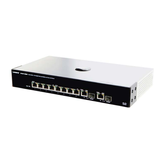
- Page 1 SFE1000P 8-port 10/100 Ethernet Switch with PoE Administration Guide March 2008 SFE1000P 8-port 10/100 Ethernet Switch with PoE Administration Guide...
-
Page 2: Document Revision History
Specifications are subject to change without notice. Linksys, the Cisco Systems logo, the Linksys Logo, and the Linksys One logo are registered trademarks of Cisco Systems, Inc. All other trademarks mentioned in this document are the property of their respective owners. -
Page 3: Table Of Contents
Contents SFE1000P Gigabit Ethernet Switch Administration Guide Chapter 1: Preface ....1 Audience Purpose Organization Chapter 2: Getting Started ....3... - Page 4 Contents SFE1000P Gigabit Ethernet Switch Administration Guide Defining 802.1x Defining Port Authentication Modifying 8021X Security Defining Multiple Hosts Modifying Multiple Host Settings Defining Authenticated Host Defining Access Control Defining MAC Based ACL Adding Rule to MAC Based ACL Defining IP Based ACL...
- Page 5 Contents SFE1000P Gigabit Ethernet Switch Administration Guide Enabling ARP Modifying ARP Settings Chapter 9: Defining Address Tables ... . . 66 Defining Static Addresses Defining Dynamic Addresses Chapter 10: Configuring Multicast Forwarding .
- Page 6 Contents SFE1000P Gigabit Ethernet Switch Administration Guide Modifying Interface Priorities Defining Queue Mapping CoS to Queue Mapping DSCP to Queue Configuring Bandwidth Defining Advanced Mode Configuring DSCP Mapping Defining Class Mapping Defining Aggregate Policer Modifying QoS Aggregate Policer Configuring Policy Table...
- Page 7 Appendix A: Console Interface Configuration ..144 Overview Configuring the HyperTerminal Application Connecting to the SFE1000P through a Telnet Session Appendix B: Contacts ....148 US/Canada Contacts EU Contacts Appendix C: Warranty Information .
- Page 8 Contents SFE1000P Gigabit Ethernet Switch Administration Guide Appendix F: Safety Information ....162 Meaning of the Warning Symbol General Safety Information Appendix G: Software License Agreement ..164...
-
Page 9: Chapter 1: Preface
This publication is designed for people who have some experience installing networking equipment such as routers, hubs, servers, and switches. We assume the person installing and troubleshooting the SFE1000P is familiar with electronic circuitry and wiring practices and has experience as an electronic or electromechanical technician. - Page 10 Chapter 18, "Managing Device Diagnostics," contains information for configuring port mirroring, running cable tests, and viewing device operational information. • Appendix B, "Contacts," is a listing of support resources and contact information for such. • Appendix C, "Warranty Information," is the Linksys warranty. Chapter 1: Preface Organization...
-
Page 11: Chapter 2: Getting Started
Resetting the Device • Logging Off The Device The following diagram illustrates how the SFE1000P fits into your network. Starting the Application This section contains information for starting the Linksys User Interface. NOTE: By default, the IP address of the device is assigned dynamically. - Page 12 Chapter SFE1000P Gigabit Ethernet Switch Administration Guide Enter Network Password Page 3. Enter a user name and password. The default user name is "admin" The device is not configured with a default password, and can be configured without entering a password.
-
Page 13: Understanding The Interface
Chapter SFE1000P Gigabit Ethernet Switch Administration Guide Embedded Web System Home Page Understanding the Interface The following table lists the interface components with their corresponding numbers: Interface Components Component Description The Tree View provides easy navigation through the configurable Tree View device features.The main branches expand to provide the subfeatures. -
Page 14: Device Representation
Linksys User Interface Components This section provides the following additional information: • Device Representation — Provides an explanation of the Linksys user interface buttons, including both management buttons and task icons. • Using the Linksys Management Buttons — Provides instructions for adding, modifying, and deleting device parameters. -
Page 15: Using The Linksys Management Buttons
Resets the settlings of a selected port to the default settings Test Performs cable tests immediately. Using Screen and Table Options Linksys contains screens and tables for configuring devices. This section contains the following topics: • Adding Device Information •... -
Page 16: Modifying Device Information
Chapter SFE1000P Gigabit Ethernet Switch Administration Guide 1. Open an EWS page. 2. Click the Add button. An add page opens, for example, the Add SNTP Server Page: Add SNTP Server 3. Define the fields. 4. Click Apply. The configuration information is saved, and the device is updated. -
Page 17: Resetting The Device
3. Enter a user name and password to reconnect to the Web Interface, if the device is not part of a full Linksys One system. If the device is part of a Linksys One system, login is automatically done from the Service Router. -
Page 18: Chapter 3: Managing Device Information
Chapter SFE1000P Gigabit Ethernet Switch Administration Guide Managing Device Information This section provides information for defining both basic and advanced system information. This section contains the following topics: • Understanding the Device Zoom View • Defining General System Information •... -
Page 19: Defining General System Information
Chapter SFE1000P Gigabit Ethernet Switch Administration Guide Defining General System Information The System Information Page contains parameters for configuring general device information. 1. Click the System > System Management > System Information. The System Information Page opens: System Information Page 2. - Page 20 2. Click the Reset button. 3. Enter a user name and password to reconnect to the Web Interface. If the device is part of a Linksys One system, login is automatically done from the Service Router. Chapter 3: Managing Device Information...
-
Page 21: Chapter 4: Managing Power-Over-Ethernet Devices
Chapter SFE1000P Gigabit Ethernet Switch Administration Guide Managing Power-over-Ethernet Devices Power-over-Ethernet (PoE) provides power to devices over existing LAN cabling, without updating or modifying the network infrastructure. Power-over-Ethernet removes the necessity of placing network devices next to power sources. Power-over-Ethernet can be used in the following applications: •... - Page 22 Chapter SFE1000P Gigabit Ethernet Switch Administration Guide PoE Settings Page 2. Click the Edit button. The Edit PoE opens: Edit PoE 3. Define the relevant fields. 4. Click Apply. The PoE Settings are defined, and the device is updated. Chapter 4: Managing Power-over-Ethernet Devices...
-
Page 23: Chapter 5: Configuring Device Security
Chapter SFE1000P Gigabit Ethernet Switch Administration Guide Configuring Device Security The Security Suite contains the following sections: • Passwords Management • Defining Authentication • Defining Access Method • Defining Traffic Control • Defining 802.1x • Defining Access Control • Defining DoS Prevention Passwords Management This section contains information for defining passwords. - Page 24 Chapter SFE1000P Gigabit Ethernet Switch Administration Guide User Authentication Page. 2. Click the Add button. The Add Local User Page opens: Add Local User Page 3. Define the relevant fields. 4. Click Apply. The local user settings are modified. Chapter 5: Configuring Device Security...
-
Page 25: Modifying The Local User Settings
Chapter SFE1000P Gigabit Ethernet Switch Administration Guide Modifying the Local User Settings 1. Click Security Suite > Passwords Management > User Authentication. The User Authentication Page Opens: 2. Click the Edit Button. The Edit Local User Page opens: Edit Local User Page 3. -
Page 26: Defining Authentication Profiles
Chapter SFE1000P Gigabit Ethernet Switch Administration Guide Defining Authentication Profiles Authentication profiles allow network administrators to assign authentication methods for user authentication. User authentication can be performed locally or on an external server. User authentication occurs in the order the methods are selected. If the first authentication method is not available, the next selected method is used. -
Page 27: Modify The Authentication Profile
Chapter SFE1000P Gigabit Ethernet Switch Administration Guide Modify the Authentication Profile 1. Click Security Suite > Authentication > Profiles. The Profiles Page opens: 2. Click the Edit Button. The Edit Authentication Profile Page opens: Edit Authentication Profile Page 3. Define the relevant fields. -
Page 28: Defining Tacacs
Chapter SFE1000P Gigabit Ethernet Switch Administration Guide Mapping Profiles Page 2. Define the relevant fields. 3. Click Apply. Mapping Profiles is defined, and the device is updated. Defining TACACS+ The devices provide Terminal Access Controller Access Control System (TACACS+) client support. - Page 29 Chapter SFE1000P Gigabit Ethernet Switch Administration Guide To define TACACS+: 1. Click Security Suite > Authentication > TACACS+. The TACACS+ Page opens: TACACS+ Page 2. Click The Add button. The Add TACACS+ Server Page opens: Add TACACS+ Server Page 3. Add a TACACS+ server.
-
Page 30: Modifying Tacacs+ Settings
Chapter SFE1000P Gigabit Ethernet Switch Administration Guide Modifying TACACS+ Settings 1. Click Security Management > Security Suite > Authentication. The TACACS+ Page opens: 2. Click the Edit Button. The TACACS+ Page opens: TACACS+ Page 3. Define the relevant fields. 4. Click Apply. The TACACS+ settings are modified, and the device is updated. - Page 31 Chapter SFE1000P Gigabit Ethernet Switch Administration Guide RADIUS Page 2. Click the Add button. The Add Radius Server Page opens: Add Radius Server Page 3. Define the relevant fields. 4. Click Apply. The Radius Server is added, and the device is updated.
-
Page 32: Modifying Radius Server Settings
Chapter SFE1000P Gigabit Ethernet Switch Administration Guide Modifying RADIUS Server Settings 1. Click Security Suite > Authentication > RADIUS. The RADIUS Page opens: 2. Click the Edit button. The Edit RADIUS Settings Page opens: Edit RADIUS Settings Page 3. Define the relevant fields. - Page 33 Chapter SFE1000P Gigabit Ethernet Switch Administration Guide • Secure HTTP (HTTPS) • SNMP Management access to different management methods may differ between user groups. For example, User Group 1 can access the switch module only via an HTTPS session, while User Group 2 can access the switch module via both HTTPS and Telnet sessions.
-
Page 34: Defining Profile Rules
Chapter SFE1000P Gigabit Ethernet Switch Administration Guide Add Access Profile Page 3. Define the relevant fields. 4. Click Apply. The access profile is added, and the device is updated. Defining Profile Rules Access profiles can contain up to 128 rules that determine which users can manage the switch module, and by which methods. - Page 35 Chapter SFE1000P Gigabit Ethernet Switch Administration Guide To define profile rules: 1. Click Security Suite > Access Method > Profile Rules. The Profile Rules Page opens: Profile Rules Page 2. Click the Add button. The Add Profile Rule Page opens: Add Profile Rule Page 3.
-
Page 36: Modifying Profile Rules
Chapter SFE1000P Gigabit Ethernet Switch Administration Guide Modifying Profile Rules 1. Click Security Suite > Access Method > Profile Rules. The Profile Rules Page opens: 2. Click the Edit button. The Edit Profile Rule Page opens: Edit Profile Rule Page 3. -
Page 37: Defining Traffic Control
Chapter SFE1000P Gigabit Ethernet Switch Administration Guide Defining Traffic Control The Traffic Control section contains the following pages: • Defining Storm Control • Defining Port Security Defining Storm Control Storm Control enables limiting the amount of Multicast and Broadcast frames accepted and forwarded by the device. -
Page 38: Modifying Storm Control
Chapter SFE1000P Gigabit Ethernet Switch Administration Guide Modifying Storm Control 1. Click Security Suite > Traffic Control > Storm Control. The Storm Control Page opens: 2. Click the Edit Button. The Edit Storm Control Page opens: Edit Storm Control Page 3. -
Page 39: Modifying Port Security
Chapter SFE1000P Gigabit Ethernet Switch Administration Guide Perform the following to define port security: 1. Click Security Suite > Traffic Control > Port Security. The Port Security Page opens: Port Security Page 2. Define the relevant fields. 3. Click Apply. Port security is defined, and the device is updated. -
Page 40: Defining 802.1X
Chapter SFE1000P Gigabit Ethernet Switch Administration Guide Defining 802.1x Port based authentication enables authenticating system users on a per-port basis via a external server. Only authenticated and approved system users can transmit and receive data. Ports are authenticated via the RADIUS server using the Extensible Authentication Protocol (EAP). Port Authentication includes: •... -
Page 41: Defining Port Authentication
Chapter SFE1000P Gigabit Ethernet Switch Administration Guide 1. Click Security Suite > 802.1X > Properties. The 802.1X Properties Page opens: 802.1X Properties Page 2. Define the relevant fields. 3. Click Apply. The 802.1X properties are defined, and the device is updated. -
Page 42: Modifying 8021X Security
Chapter SFE1000P Gigabit Ethernet Switch Administration Guide Modifying 8021X Security 1. Click Security Suite > 802.1X > Properties. The 802.1X Properties Page opens: 2. Click the Edit button. The Port Authentication Settings Page opens: Port Authentication Settings Page 3. Modify the relevant fields. -
Page 43: Defining Multiple Hosts
Chapter SFE1000P Gigabit Ethernet Switch Administration Guide Defining Multiple Hosts The 802.1X Multiple Host Page allows network managers to configure advanced port-based authentication settings for specific ports and VLANs. 1. Click Security Suite > 802.1X > Multiple Host. The 802.1X Multiple Host Page opens: 802.1X Multiple Host Page... -
Page 44: Defining Authenticated Host
Chapter SFE1000P Gigabit Ethernet Switch Administration Guide Defining Authenticated Host The Authenticated Host Page contains a list of authenticated users. 1. Click Security Suite > 802.1X > Authenticated Host. The Authenticated Host Page opens: Authenticated Host Page 2. Define the relevant fields. -
Page 45: Defining Mac Based Acl
Chapter SFE1000P Gigabit Ethernet Switch Administration Guide Defining MAC Based ACL The MAC Based ACL Page page allows a MAC-based Access Control List (ACL) to be defined. The table lists Access Control Elements (ACE) rules, which can be added only if the ACL is not bound to an interface. -
Page 46: Adding Rule To Mac Based Acl
Chapter SFE1000P Gigabit Ethernet Switch Administration Guide Adding Rule to MAC Based ACL 1. Select an existing ACL. 2. Click the Add Rule button. The Add MAC Based Rule Page opens: Add MAC Based Rule Page 3. Define the relevant fields. - Page 47 Chapter SFE1000P Gigabit Ethernet Switch Administration Guide 1. Click Security Suite >Access Control > IP Based ACL. The IP Based ACL Page opens: IP Based ACL Page 2. Click the Add Button. The Add IP Based ACL Page opens: Add IP Based ACL Page 3.
-
Page 48: Adding An Ip Based Rule
Chapter SFE1000P Gigabit Ethernet Switch Administration Guide Adding an IP Based Rule 1. Click Security Suite > Access Control > IP Based ACL. The IP Based ACL Page opens: 2. Click the Add ACL Rule button. The Add IP Based Rule Page opens: Add IP Based Rule Page 3. -
Page 49: Modifying Acl Binding
Chapter SFE1000P Gigabit Ethernet Switch Administration Guide 1. Click Security Suite > Access Control > ACL Binding. The ACL Binding Page opens ACL Binding Page 2. Define the relevant fields. 3. Click Apply. The ACL binding settings are modified, and the device is updated. -
Page 50: Global Settings
Chapter SFE1000P Gigabit Ethernet Switch Administration Guide Global Settings 1. Click Security Suite > Dos Prevention > Global Settings. The Global Settings Page opens: Global Settings Page 2. Define the relevant fields. 3. Click Apply. The Dos prevention global settings are defined, and the device is updated. - Page 51 Chapter SFE1000P Gigabit Ethernet Switch Administration Guide 2. Click the Add button. The Add Martian Addresses Page opens: Add Martian Addresses Page 3. Define the relevant fields. 4. Click Apply. The martian addresses are added, and the device is updated.
-
Page 52: Chapter 6: Configuring Device Interfaces
Chapter SFE1000P Gigabit Ethernet Switch Administration Guide Configuring Device Interfaces This section contains information for configuring ports and contains the following topic: • Defining Port Settings • Defining LAG Management • Defining LAG Settings • Configuring LACP Defining Port Settings The Port Settings Page contains fields for defining port parameters. -
Page 53: Defining Lag Management
Chapter SFE1000P Gigabit Ethernet Switch Administration Guide Edit Port Settings Page 3. Define the relevant fields. 4. Click Apply. The Port Settings are modified, and the device is updated. Defining LAG Management Link Aggregation optimizes port usage by linking a group of ports together to form a single LAG. - Page 54 Chapter SFE1000P Gigabit Ethernet Switch Administration Guide • The port is in full-duplex mode. • All ports in the LAG have the same ingress filtering and tagged modes. • All ports in the LAG have the same back pressure and flow control modes.
-
Page 55: Modifying Lag Membership
Chapter SFE1000P Gigabit Ethernet Switch Administration Guide Modifying LAG Membership 1. Click Bridging > Port Management > LAG Management. The LAG Management Page opens: 2. Click the Edit button. The Edit LAG Membership Page opens: Edit LAG Membership Page 3. Define the relevant fields. -
Page 56: Defining Lag Settings
Chapter SFE1000P Gigabit Ethernet Switch Administration Guide Defining LAG Settings Link Aggregated Groups optimize port usage by linking a group of ports together to form a single aggregated group. Link aggregated groups multiply the bandwidth between the devices, increase port flexibility, and provide link redundancy. -
Page 57: Configuring Lacp
Chapter SFE1000P Gigabit Ethernet Switch Administration Guide LAG Configuration Settings 3. Define the relevant fields. 4. Click Apply. The LAG configuration settings are modified, and the device is updated. Configuring LACP Aggregate ports can be linked into link-aggregation port-groups. Each group is comprised of ports with the same speed, set to full-duplex operations. -
Page 58: Modify Lacp Parameter Settings
Chapter SFE1000P Gigabit Ethernet Switch Administration Guide To define LACP: 1. Click Bridging > Port Managing > LACP. The LACP Page opens: LACP Page 2. Define the relevant fields. 3. Click Apply. The LACP settings are modified, and the device is updated. -
Page 59: Chapter 7: Configuring Vlans
Chapter SFE1000P Gigabit Ethernet Switch Administration Guide Configuring VLANs VLANs are logical subgroups with a Local Area Network (LAN) which combine user stations and network devices into a single unit, regardless of the physical LAN segment to which they are attached. -
Page 60: Defining Vlan Properties
Chapter SFE1000P Gigabit Ethernet Switch Administration Guide Defining VLAN Properties The VLAN Properties Page provides information and global parameters for configuring and working with VLANs. 1. Click Bridging > VLAN Management > Properties. The Properties Page opens. Properties Page 2. Click the Add button. The Add VLAN Page opens: Add VLAN Page 3. -
Page 61: Modifying Vlans
Chapter SFE1000P Gigabit Ethernet Switch Administration Guide Modifying VLANs 1. Click Bridging > VLAN Management > Properties. The Properties Page opens. 2. Click Edit. The Edit VLAN Page opens: Edit VLAN Page 3. Define the relevant fields. 4. Click Apply. The VLAN Settings are defined, and the device is updated. -
Page 62: Modifying Vlan Membership
Chapter SFE1000P Gigabit Ethernet Switch Administration Guide Modifying VLAN Membership 1. Click Bridging > VLAN Management > Membership. The VLAN Membership Page opens: 2. Click the Edit button. The Edit VLAN Membership Page opens: Edit VLAN Membership Page 3. Define the relevant fields. -
Page 63: Modifying Vlan Interface Settings
Chapter SFE1000P Gigabit Ethernet Switch Administration Guide 3. Click Apply. The VLAN Interface Settings are defined, and the device is updated. Modifying VLAN Interface Settings 1. Click Bridging > VLAN Management > Interface Setting. The VLAN Interface Setting Page opens: 2. -
Page 64: Modifying Gvrp Settings
Chapter SFE1000P Gigabit Ethernet Switch Administration Guide To define GVRP: 1. Click Bridging > VLAN Management > GVRP Settings. The GVRP Settings Page opens: GVRP Settings Page 2. Define the relevant fields. 3. Click Apply. The GVRP Settings are defined, and the device is updated. -
Page 65: Defining Vlan Protocol Group
Chapter SFE1000P Gigabit Ethernet Switch Administration Guide Defining VLAN Protocol Group The Protocol Group Page contains information defining protocol names and the VLAN Ethernet type. Interfaces can be classified as a specific protocol based interface. 1. Click Bridging > VLAN Management > Protocol Group. The Protocol Group Page opens: Protocol Group Page 2. -
Page 66: Modifying Protocol Groups
Chapter SFE1000P Gigabit Ethernet Switch Administration Guide Modifying Protocol Groups The Protocol Group Settings Page provides information for configuring existing VLAN protocol groups. 1. Click Bridging > VLAN Management > Protocol Group. The Protocol Group Page opens: 2. Click the Edit Button. The Protocol Group Settings Page opens: Protocol Group Settings Page 3. - Page 67 Chapter SFE1000P Gigabit Ethernet Switch Administration Guide Add Protocol Port to VLAN Page 3. Define the relevant fields. 4. Click Apply. The protocol ports are mapped to VLANs, and the device is updated. Chapter 7: Configuring VLANs Defining VLAN Protocol Port...
-
Page 68: Chapter 8: Configuring Ip Information
Chapter SFE1000P Gigabit Ethernet Switch Administration Guide Configuring IP Information This section provides information for defining device IP addresses, and includes the following topics: • Domain Name System • Configuring Layer 2IP Addresses • Configuring Layer 3 Domain Name System Domain Name System (DNS) converts user-defined domain names into IP addresses. - Page 69 Chapter SFE1000P Gigabit Ethernet Switch Administration Guide To enable a DNS client: 1. Click System > System Management > Domain Name System > DNS Servers. The DNS Servers Page opens: DNS Servers Page 2. Click the Add button. The Add DNS Server Page opens: Add DNS Server Page 3.
-
Page 70: Mapping Dns Hosts
Chapter SFE1000P Gigabit Ethernet Switch Administration Guide Mapping DNS Hosts The Host Mapping Page provides information for defining DNS Host Mapping. 1. Click System > System Management > Domain Name System > Host Mapping. The Host Mapping Page opens: Host Mapping Page 2. -
Page 71: Configuring Layer 2Ip Addresses
Chapter SFE1000P Gigabit Ethernet Switch Administration Guide Configuring Layer 2IP Addresses The IP address and default gateway can be either dynamically or statically configured. In Layer 2, a static IP address is configured on the VLAN Management Properties Page. The Management VLAN is set to VLAN 100 by default, but can be modified. -
Page 72: Enabling Arp
Chapter SFE1000P Gigabit Ethernet Switch Administration Guide Enabling ARP The Address Resolution Protocol (ARP) is a TCP/IP protocol that converts IP addresses into physical addresses. The ARP table is used to maintain a correlation between each MAC address and its corresponding IP address. -
Page 73: Modifying Arp Settings
Chapter SFE1000P Gigabit Ethernet Switch Administration Guide Modifying ARP Settings 1. Click System > System Management > IP Addressing > ARP. The ARP Page opens: 2. Click the Edit button. The Edit ARP Page opens: Edit ARP Page 3. Define the relevant fields. -
Page 74: Chapter 9: Defining Address Tables
Chapter SFE1000P Gigabit Ethernet Switch Administration Guide Defining Address Tables MAC addresses are stored in either the Static Address or the Dynamic Address databases. A packet addressed to a destination stored in one of the databases is forwarded immediately to the port. The Dynamic Address Table can be sorted by interface, VLAN, and MAC Address. -
Page 75: Defining Dynamic Addresses
Chapter SFE1000P Gigabit Ethernet Switch Administration Guide Add Static MAC Address Page 3. Define the relevant fields. 4. Click Apply. The Static MAC Address is added, and the device is updated. Defining Dynamic Addresses The Dynamic Address Table contains the MAC addresses learned by monitoring the source address for traffic entering the switch. - Page 76 Chapter SFE1000P Gigabit Ethernet Switch Administration Guide 1. Click Bridging > Address Tables > Dynamic. The Dynamic Page opens: Dynamic Page 2. Define the relevant fields. 3. Click Query. The Dynamic MAC Address Table is queried, and the results are displayed.
-
Page 77: Chapter 10: Configuring Multicast Forwarding
Chapter SFE1000P Gigabit Ethernet Switch Administration Guide Configuring Multicast Forwarding The Multicast section contains the following pages: • IGMP Snooping • Defining Multicast Bridging Groups • Defining Multicast Forwarding IGMP Snooping When IGMP Snooping is enabled globally, all IGMP packets are forwarded to the CPU. The CPU analyzes the incoming packets and determines: •... -
Page 78: Modifying Igmp Snooping
Chapter SFE1000P Gigabit Ethernet Switch Administration Guide Modifying IGMP Snooping 1. Click Bridging > Multicast > ICMP Snooping. The IGMP Snooping Page opens: 2. Click the Edit button. The Edit IGMP Snooping Page: Edit IGMP Snooping Page 3. Define the relevant fields. - Page 79 Chapter SFE1000P Gigabit Ethernet Switch Administration Guide To define Multicast groups: 1. Click Bridging > Multicast> Multicast Groups. The Multicast Group Page opens: Multicast Group Page 2. Click the Add button. The Add Multicast Group Page opens: Add Multicast Group Page 3.
-
Page 80: Modifying A Multicast Group
Chapter SFE1000P Gigabit Ethernet Switch Administration Guide Modifying a Multicast Group 1. Click Bridging > Bridge Multicast> Multicast Groups. The Multicast Group Page opens: 2. Click the Edit button. The Edit Multicast Group Page opens. Edit Multicast Group Page 3. Define the Multicast Group Port Settings. -
Page 81: Modifying Multicast Forwarding
Chapter SFE1000P Gigabit Ethernet Switch Administration Guide Multicast Forward Page 2. Define the relevant fields. 3. Click Apply. The multicast forward all settings are defined, and the device is updated. Modifying Multicast Forwarding 1. Click Bridging > Multicast > Forward. The Multicast Forward Page opens: 2. -
Page 82: Chapter 11: Configuring Spanning Tree
Chapter SFE1000P Gigabit Ethernet Switch Administration Guide Configuring Spanning Tree The Spanning Tree Protocol (STP) provides tree topography for any arrangement of bridges. STP also provides one path between end stations on a network, eliminating loops. Loops occur when alternate routes exist between hosts. Loops in an extended network can cause bridges to forward traffic indefinitely, resulting in increased traffic and reducing network efficiency. -
Page 83: Defining Stp Properties
Chapter SFE1000P Gigabit Ethernet Switch Administration Guide Defining STP Properties The STP Properties Page contains parameters for enabling STP on the device. The STP Properties Page is divided into three areas, Global Settings, Bridge Settings. and Designated Root. 1. Click Bridging > Spanning Tree > Properties. The STP Properties Page opens: STP Properties Page 2. -
Page 84: Defining Interface Settings
Chapter SFE1000P Gigabit Ethernet Switch Administration Guide Defining Interface Settings Network administrators can assign STP settings to specific interfaces using the STP Interface Settings Page. To assign STP settings to an interface: 1. Click Bridging > Spanning Tree > Interface Settings. The Interface Settings Page opens: Interface Settings Page 2. -
Page 85: Modifying Interface Settings
Chapter SFE1000P Gigabit Ethernet Switch Administration Guide Modifying Interface Settings 1. Click Bridging > Spanning Tree > Interface Settings. The Interface Settings Page opens: 2. Click the Edit button. The Edit Interface Settings Page opens: Edit Interface Settings Page 3. Define the relevant fields. -
Page 86: Defining Rapid Spanning Tree
Chapter SFE1000P Gigabit Ethernet Switch Administration Guide Defining Rapid Spanning Tree While the classic spanning tree prevents Layer 2 forwarding loops in a general network topology, convergence can take between 30-60 seconds. This time may delay detecting possible loops, and propagating status topology changes. -
Page 87: Modifying Rtsp
Chapter SFE1000P Gigabit Ethernet Switch Administration Guide Modifying RTSP 1. Click Bridging > Spanning Tree > RSTP. The RSTP Page opens: 2. Click the Edit button. The Edit Rapid Spanning Tree Page opens: Edit Rapid Spanning Tree Page 3. Define the relevant fields. -
Page 88: Defining Mstp Properties
Chapter SFE1000P Gigabit Ethernet Switch Administration Guide Defining MSTP Properties The MSTP Properties Page contains information for defining global MSTP settings, including region names, MSTP revisions, and maximum hops. To define MSTP: 1. Click Bridging > Spanning Tree > MSTP > Properties. The MSTP Properties Page opens: MSTP Properties Page 2. -
Page 89: Mapping Mstp Instances To Vlan
Chapter SFE1000P Gigabit Ethernet Switch Administration Guide Mapping MSTP Instances to VLAN MSTP maps VLANs into STP instances. Packets assigned to various VLANs are transmitted along different paths within Multiple Spanning Tree Regions (MST Regions). Regions are one or more Multiple Spanning Tree bridges by which frames can be transmitted. -
Page 90: Defining Mstp Instance Settings
Chapter SFE1000P Gigabit Ethernet Switch Administration Guide Defining MSTP Instance Settings MSTP maps VLANs into STP instances. Packets assigned to various VLANs are transmitted along different paths within Multiple Spanning Tree Regions (MST Regions). Regions are one or more Multiple Spanning Tree bridges by which frames can be transmitted. In configuring MSTP, the MST region to which the device belongs is defined. -
Page 91: Defining Mstp Interface Settings
Chapter SFE1000P Gigabit Ethernet Switch Administration Guide Defining MSTP Interface Settings Network Administrators can define MSTP Instances settings using the MSTP Interface Settings Page. 1. Click Bridging > Spanning Tree > MSTP > Interface Settings. The MSTP Interface Settings Page... - Page 92 Chapter SFE1000P Gigabit Ethernet Switch Administration Guide Interface Table Page 3. Define the relevant fields. 4. Click Apply. The Interface settings are modified, and the device is updated. Chapter 11: Configuring Spanning Tree Defining Multiple Spanning Tree...
-
Page 93: Chapter 12: Configuring Snmp
Chapter SFE1000P Gigabit Ethernet Switch Administration Guide Configuring SNMP The Simple Network Management Protocol (SNMP) provides a method for managing network devices. The device supports the following SNMP versions: SNMP v1 and v2 SNMP agents maintain a list of variables that are used to manage the device. The variables are defined in the Management Information Base (MIB). -
Page 94: Configuring Snmp Security
Chapter SFE1000P Gigabit Ethernet Switch Administration Guide Configuring SNMP Security The Security section contains the following pages: • Defining the SNMP Engine ID • Defining SNMP Views • Defining SNMP Users • Define SNMP Groups • Defining SNMP Communities Defining the SNMP Engine ID The Engine ID Page provides information for defining the device engine ID. -
Page 95: Defining Snmp Views
Chapter SFE1000P Gigabit Ethernet Switch Administration Guide Defining SNMP Views SNMP Views provide access or block access to device features or feature aspects. For example, a view can be defined that states that SNMP Group A has Read Only (R/O) access to Multicast groups, while SNMP Group B has Read-Write (R/W) access to Multicast groups. -
Page 96: Defining Snmp Users
Chapter SFE1000P Gigabit Ethernet Switch Administration Guide Defining SNMP Users The SNMP Users Page provides information for creating SNMP groups, and assigning SNMP access control privileges to SNMP groups. Groups allow network managers to assign access rights to specific device features, or feature aspects. -
Page 97: Modifying Snmp Users
Chapter SFE1000P Gigabit Ethernet Switch Administration Guide Modifying SNMP Users The Edit SNMP User Page provides information for assigning SNMP access control privileges to SNMP groups. The Edit SNMP User Page contains the following fields. 1. Click System > SNMP > Security > Users to open the Edit SNMP User Page 2. -
Page 98: Modifying Snmp Group Profile Settings
Chapter SFE1000P Gigabit Ethernet Switch Administration Guide Add SNMP Group Profile Page 3. Define the relevant fields. 4. Click Apply. The SNMP settings are modified, and the device is updated. Modifying SNMP Group Profile Settings 1. Click System > SNMP > Security > Groups. The SNMP Groups Profile Page opens: 2. -
Page 99: Defining Snmp Communities
Chapter SFE1000P Gigabit Ethernet Switch Administration Guide Defining SNMP Communities The Access rights are managed by defining communities in the SNMP Communities Page. When the community names are changed, access rights are also changed. SNMP communities are defined only for SNMP v1 and SNMP v2c. -
Page 100: Modifying Snmp Community Settings
Chapter SFE1000P Gigabit Ethernet Switch Administration Guide Modifying SNMP Community Settings 1. Click System > SNMP > Security > Communities. The SNMP Communities Page opens: 2. Click the Edit Button. The Edit SNMP Community Page: Edit SNMP Community Page 3. Define the relevant fields. -
Page 101: Defining Trap Management
Chapter SFE1000P Gigabit Ethernet Switch Administration Guide Defining Trap Management The Defining Trap Management section contains the following pages: • Defining Trap Settings • Configuring Station Management • Defining SNMP Filter Settings Defining Trap Settings The Trap Settings Page contains parameters for defining SNMP notification parameters. - Page 102 Chapter SFE1000P Gigabit Ethernet Switch Administration Guide Traps indicating status changes are issued by the switch to specified trap managers. Specify the trap managers so that key events are reported by this switch to the management station. Specify up to five management stations that receive authentication failure messages and other trap messages from the switch.
- Page 103 Chapter SFE1000P Gigabit Ethernet Switch Administration Guide Add SNMP Notification Recipient Page 3. Define the relevant fields. 4. Click Apply. The SNMP Notification Recipient settings are defined, and the device is updated. Chapter 12: Configuring SNMP Defining Trap Management...
-
Page 104: Modifying Snmp Notifications Settings
Chapter SFE1000P Gigabit Ethernet Switch Administration Guide Modifying SNMP Notifications Settings The Edit SNMP Notification Page allows system administrators to define notification settings. The Edit SNMP Notification Page is divided into four areas, Notification Recipient, SNMPv1,2 Notification Recipient, SNMPv3 Notification Recipient and UDP Port Notification Recipient. - Page 105 Chapter SFE1000P Gigabit Ethernet Switch Administration Guide Filter Settings Page 2. Click the Add button. The Add SNMP Notification Filter Page opens: Add SNMP Notification Filter Page 3. Define the relevant fields. 4. Click Apply. The SNMP Notification Filter is added to the list, and the device is updated.
-
Page 106: Chapter 13: Configuring Quality Of Service
Chapter SFE1000P Gigabit Ethernet Switch Administration Guide Configuring Quality of Service Network traffic is usually unpredictable, and the only basic assurance that can be offered is best effort traffic delivery. To overcome this challenge, Quality of Service (QoS) is applied throughout the network. -
Page 107: Defining General Settings
Chapter SFE1000P Gigabit Ethernet Switch Administration Guide The Quality of Service section contains the following section: • Defining General Settings • Defining Advanced Mode • Defining QoS Basic Mode The section also contains the following pages: • Configuring Policy Table •... -
Page 108: Defining Cos
Chapter SFE1000P Gigabit Ethernet Switch Administration Guide Defining CoS The CoS Page contains fields for enabling or disabling CoS (Basic or Advanced mode). In addition, the default CoS for each port or LAG is definable. 1. Click Quality of Service > General > CoS. The CoS Page opens: CoS Page 2. -
Page 109: Defining Queue
Chapter SFE1000P Gigabit Ethernet Switch Administration Guide Defining Queue The Queue Page contains fields for defining the QoS queue forwarding types. 1. Click Quality of Service > General > Queues. The Queue Page opens: Queue Page 2. Define the queues. -
Page 110: Mapping Dscp To Queue
Chapter SFE1000P Gigabit Ethernet Switch Administration Guide Cos to Queue Page 2. Define the relevant fields. 3. Click Apply. CoS to queues are mapped, and the device is updated. Mapping DSCP to Queue The DSCP to Queue Page enables mapping DSCP values to specific queues. -
Page 111: Configuring Bandwidth
Chapter SFE1000P Gigabit Ethernet Switch Administration Guide Configuring Bandwidth The Bandwidth Page allows network managers to define the bandwidth settings for specified egress and ingress interfaces. Rate Limits and Shaping are defined per interface: • Rate Limit sets the maximum bandwidth allowed on ingress interfaces. -
Page 112: Defining Advanced Mode
Chapter SFE1000P Gigabit Ethernet Switch Administration Guide 4. Click Apply. The bandwidth settings are modified, and the device is updated. Defining Advanced Mode Advanced QoS mode provides rules for specifying flow classification and assigning rule actions that relate to bandwidth management. The rules are defined in classification control lists (CCL). -
Page 113: Configuring Dscp Mapping
Chapter SFE1000P Gigabit Ethernet Switch Administration Guide Configuring DSCP Mapping The DSCP Mapping Page enables mapping Differentiated Services Code Point (DSCP) values from incoming packets to DSCP values in outgoing packets. This information is important when traffic exceeds user-defined limits. -
Page 114: Defining Class Mapping
Chapter SFE1000P Gigabit Ethernet Switch Administration Guide Defining Class Mapping The Class Mapping Page contains parameters for defining class maps. One IP ACL and/or one MAC ACL comprise a class map. Class maps are configured to match packet criteria, and are matched to packets on a first-fit basis. -
Page 115: Defining Aggregate Policer
Chapter SFE1000P Gigabit Ethernet Switch Administration Guide Defining Aggregate Policer A policy is a collection of classes, each of which is a combination of a class map and a QoS action to apply to matching traffic. Classes are applied in a first-fit manner within a policy. -
Page 116: Modifying Qos Aggregate Policer
Chapter SFE1000P Gigabit Ethernet Switch Administration Guide Add QoS Aggregate Policer Page 3. Define the relevant fields. 4. Click Apply. The Aggregate policer is added, and the device is updated. Modifying QoS Aggregate Policer 1. Click Quality of Service > Advanced > Aggregate Policer. The Aggregate Policer Page opens: 2. -
Page 117: Configuring Policy Table
Chapter SFE1000P Gigabit Ethernet Switch Administration Guide Configuring Policy Table In the Policy Table Page, QoS policies are set up and assigned to interfaces. 1. Click Quality of Service > Advanced > Policy Table. The Policy Table Page opens: Policy Table Page 2. -
Page 118: Modifying The Qos Policy Profile
Chapter SFE1000P Gigabit Ethernet Switch Administration Guide Modifying the QoS Policy Profile 1. Click Quality of Service > Advanced > QoS Policy Profile. The Edit QoS Aggregate Policer Page opens: Edit QoS Policy Profile Page 2. Define the relevant fields. -
Page 119: Defining Policy Binding
Chapter SFE1000P Gigabit Ethernet Switch Administration Guide Defining Policy Binding In the Policy Binding Page, QoS policies are associated with specific interfaces. 1. Click Quality of Service > Advanced > Policy Binding. The Policy Binding Page opens: Policy Binding Page 2. -
Page 120: Modifying Qos Policy Binding Settings
Chapter SFE1000P Gigabit Ethernet Switch Administration Guide Modifying QoS Policy Binding Settings 1. Click Quality of Service > Advanced > Policy Binding. The Policy Binding Page opens: 2. Click the Edit button. The Edit QoS Policy Binding Page opens: Edit QoS Policy Binding Page 3. - Page 121 Chapter SFE1000P Gigabit Ethernet Switch Administration Guide DSCP Mapping Page 3. Define the DSCP mappings. 4. Click Apply. The DSCP mappings are defined, and the device is updated. Chapter 13: Configuring Quality of Service Defining Advanced Mode...
-
Page 122: Chapter 14: Managing System Files
Chapter SFE1000P Gigabit Ethernet Switch Administration Guide Managing System Files The Managing System Files section contains the following sections: • File Management • Logs • Diagnostics File Management Overview The configuration file structure consists of the following configuration files: •... -
Page 123: File Management
Chapter SFE1000P Gigabit Ethernet Switch Administration Guide File Management The File Management section contains the following pages: • Firmware Upgrade • Save Configuration • Copy Files • Active Image Firmware Upgrade Firmware files are downloaded as required for upgrading the firmware version or for backing up the system configuration. -
Page 124: Save Configuration
Chapter SFE1000P Gigabit Ethernet Switch Administration Guide Save Configuration The configuration files control the operation of the switch, and contain the functional settings at the device and the port level. Configuration files are one of the following types: • Factory Default — Contains preset default parameter definitions which are downloaded with a new or upgraded version. -
Page 125: Copy Files
Chapter SFE1000P Gigabit Ethernet Switch Administration Guide Copy Files In the Copy Files Page, network administrators can copy configuration files from one device to another. 1. Click Admin > File Management > Copy Files. The Copy Files Page opens: Copy Files Page 2. -
Page 126: Active Image
Chapter SFE1000P Gigabit Ethernet Switch Administration Guide Active Image The Active Image Page allows network managers to select the Image files. 1. Click Admin > File Management > Active Image. The Active Image Page opens: Active Image Page 2. Define the relevant fields. -
Page 127: Chapter 15: Managing System Logs
Chapter SFE1000P Gigabit Ethernet Switch Administration Guide Managing System Logs The System Logs enable viewing device events in real time, and recording the events for later usage. System Logs record and manage events and report errors or informational messages. Event messages have a unique format, as per the SYSLOG protocols recommended message format for all error reporting. - Page 128 Chapter SFE1000P Gigabit Ethernet Switch Administration Guide To define Log Global Parameters: 1. Click Admin > Logs > Logs Settings. The Log Settings Page opens. Log Settings Page 2. Define the relevant fields. 3. Click Apply. The global log parameters are set, and the device is updated.
-
Page 129: Viewing The Device Memory Logs
Chapter SFE1000P Gigabit Ethernet Switch Administration Guide Viewing the Device Memory Logs The Memory Page contains all system log entries in chronological order that are saved in RAM (Cache). After restart, these log entries are deleted. To open the Memory Page: 1. -
Page 130: Viewing The Flash Logs
Chapter SFE1000P Gigabit Ethernet Switch Administration Guide Viewing the Flash Logs The Flash Page contains information about log entries saved to the Log File in FLASH, including the time the log was generated, the event severity, and a description of the log message. The Message Log is available after reboot. -
Page 131: Viewing Remote Logs
Chapter SFE1000P Gigabit Ethernet Switch Administration Guide Viewing Remote Logs The Remote Log Servers Page contains information for viewing and configuring the Remote Log Servers. New log servers and the minimum severity level of events sent to them may be added. -
Page 132: Modify Syslog Server Settings
Chapter SFE1000P Gigabit Ethernet Switch Administration Guide Modify Syslog Server Settings 1. Click Admin > Logs > Remote Log Servers. The Remote Log Servers Page opens: 2. Click the Edit button. The Edit Syslog Server Page opens: Edit Syslog Server Page The Edit Syslog Server Page contains fields for modifying Remote Log Server settings. -
Page 133: Chapter 16: Configuring System Time
Chapter SFE1000P Gigabit Ethernet Switch Administration Guide Configuring System Time The device supports the Simple Network Time Protocol (SNTP). SNTP assures accurate network device clock time synchronization up to the millisecond. Time synchronization is performed by a network SNTP server. The device operates only as an SNTP client, and cannot provide time services to other systems. -
Page 134: Defining Sntp Settings
Chapter SFE1000P Gigabit Ethernet Switch Administration Guide Defining SNTP Settings The SNTP Settings Page contains information for enabling SNTP servers, as well as adding new SNTP servers. In addition, the SNTP Settings Page enables the device to request and accept SNTP traffic from a server. -
Page 135: Defining Sntp Authentication
Chapter SFE1000P Gigabit Ethernet Switch Administration Guide Defining SNTP Authentication The SNTP Authentication Page provides parameters for performing authentication of the SNTP server. 1. Click System > System Management > Time > SNTP Authentication. The SNTP Authentication Page opens: SNTP Authentication Page 2. -
Page 136: Chapter 17: Viewing Statistics
Chapter SFE1000P Gigabit Ethernet Switch Administration Guide Viewing Statistics This section describes device statistics for RMON, interfaces, GVRP, EAP, and Etherlike statistics. This section contains the following topics: • Viewing Ethernet Statistics • Managing RMON Statistics Viewing Ethernet Statistics The Ethernet section contains the following pages: •... -
Page 137: Resetting Interface Statistics Counters
Chapter SFE1000P Gigabit Ethernet Switch Administration Guide Resetting Interface Statistics Counters 1. Click Statistics > Ethernet > Interface. The Interface Page opens: 2. Click the Clear Counters button. The interface statistics counters are cleared. Viewing Etherlike Statistics The Etherlike Page contains interface statistics. -
Page 138: Viewing Gvrp Statistics
Chapter SFE1000P Gigabit Ethernet Switch Administration Guide Viewing GVRP Statistics The GVRP Page contains statistics for GVRP communication on the device. To view GVRP statistics: 1. Click Statistics > GVRP Statistics. The GVRP Page opens. GVRP Page 2. Click the appropriate radio buttons and pulldowns to select an interface. -
Page 139: Viewing Eap Statistics
Chapter SFE1000P Gigabit Ethernet Switch Administration Guide Viewing EAP Statistics The EAP Page contains information about EAP packets received on a specific port. To view the EAP Statistics: 1. Click Statistics > Ethernet > EAP Statistics. The EAP Page opens. -
Page 140: Managing Rmon Statistics
Chapter SFE1000P Gigabit Ethernet Switch Administration Guide Managing RMON Statistics The RMON section contains the following pages: • Viewing RMON Statistics • Configuring RMON History • Configuring RMON Events • Viewing the RMON Events Logs Viewing RMON Statistics The RMON Statistics Page contains fields for viewing information about device utilization and errors that occurred on the device. -
Page 141: Configuring Rmon History
Chapter SFE1000P Gigabit Ethernet Switch Administration Guide Configuring RMON History This section contains the following topics: • Defining RMON History Control • Viewing the RMON History Table Defining RMON History Control The RMON History Control Page contains information about samples of data taken from ports. For example, the samples may include interface definitions or polling periods. -
Page 142: Modify History Control Settings
Chapter SFE1000P Gigabit Ethernet Switch Administration Guide 4. Click Apply. The entry is added to the RMON History Control Page, and the device is updated. Modify History Control Settings 1. Click Statistics > RMON > History. The RMON History Control Page opens. -
Page 143: Configuring Rmon Events
Chapter SFE1000P Gigabit Ethernet Switch Administration Guide RMON History Table Page 3. To return to the RMON History Control Page, click the Interface Table button. Configuring RMON Events This section includes the following topics: • Defining RMON Events Control •... -
Page 144: Modify Event Control Settings
Chapter SFE1000P Gigabit Ethernet Switch Administration Guide RMON Events Page 2. Click the Add button. The Add RMON Events Page opens: Add RMON Events Page 3. Define the relevant fields. 4. Click Apply. The RMON event is added, and the device is updated. -
Page 145: Viewing The Rmon Events Logs
Chapter SFE1000P Gigabit Ethernet Switch Administration Guide Edit RMON Events Page 3. Define the relevant fields. 4. Click Apply. The event control settings are modified. and the device is updated. Viewing the RMON Events Logs The RMON Events Log Page contains a list of RMON events. - Page 146 Chapter SFE1000P Gigabit Ethernet Switch Administration Guide 1. Click Statistics > RMON > Alarms. The RMON Alarms Page opens: RMON Alarms Page 2. Click the Add button. The Add RMON Alarm Page opens: Add RMON Alarm Page 3. Define the relevant fields.
-
Page 147: Modify Rmon Alarm Settings
Chapter SFE1000P Gigabit Ethernet Switch Administration Guide Modify RMON Alarm Settings 1. Click Statistics > RMON > Alarms. The RMON Alarms Page opens: 2. Click the Edit Button. The Edit RMON Alarms Page opens: Edit RMON Alarms Page 3. Define the relevant fields. -
Page 148: Chapter 18: Managing Device Diagnostics
Chapter SFE1000P Gigabit Ethernet Switch Administration Guide Managing Device Diagnostics This section contains information for configuring port mirroring, running cable tests, and viewing device operational information, and includes the following topics: • Viewing Integrated Cable Tests • Performing Optical Tests •... -
Page 149: Performing Optical Tests
Chapter SFE1000P Gigabit Ethernet Switch Administration Guide Performing Optical Tests The Optical Test Page allows network managers to perform tests on Fiber Optic cables. Optical transceiver diagnostics can be performed only when the link is present. During the port test, the port moves to a down state. -
Page 150: Configuring Port Mirroring
Chapter SFE1000P Gigabit Ethernet Switch Administration Guide Configuring Port Mirroring Port Mirroring monitors and mirrors network traffic by forwarding copies of incoming and outgoing packets from one port to a monitoring port. Port mirroring can be used as diagnostic tool and/or a debugging feature. -
Page 151: Modifying Port Mirroring
Chapter SFE1000P Gigabit Ethernet Switch Administration Guide Modifying Port Mirroring 1. Click Admin > Diagnostics > Port Mirroring. The Port Mirroring Page opens: 2. Click the Edit Button. The Edit Port Mirroring Page opens: Edit Port Mirroring Page 3. Define the relevant fields. -
Page 152: Appendix A: Console Interface Configuration
Console Interface Configuration Overview The SFE1000P features a menu-driven console interface for basic configuration of the Switch and management of your network. The Switch can be configured using CLI through the console interface or through a telnet connection. This chapter describes console interface configuration. Configuration can also be performed through the web utility. - Page 153 SFE1000P 8-port 10/100 Ethernet Switch with PoE Administration Guide 2. On the Connection Description screen, enter a name for this connection. In the example, the name of connection is SFE1000P. Select an icon for the application. Then, click the OK button. Connection Description 3.
- Page 154 Appendix SFE1000P 8-port 10/100 Ethernet Switch with PoE Administration Guide 4. Set the serial port settings as follows: Bits per second: 38400 Data bits: 8 Parity: None Stop bits: 1 Flow control: None Serial Port Settings Then, click the OK button.
-
Page 155: Connecting To The Sfe1000P Through A Telnet Session
Appendix SFE1000P 8-port 10/100 Ethernet Switch with PoE Administration Guide Connecting to the SFE1000P through a Telnet Session 1. Open a command line editor and enter telnet <ip address of the device>. Then, press the Enter key. 2. The Login screen will now appear. The first time you open the command line interface, select Edit and hit Enter. -
Page 156: Appendix B: Contacts
Appendix SFE1000P 8-port 10/100 Ethernet Switch with PoE Administration Guide Contacts For additional information or troubleshooting help, refer to the User Guide on the CD-ROM. Additional support is also available by phone or online. US/Canada Contacts • 24-Hour Technical Support: 800-326-7114 •... -
Page 157: Appendix C: Warranty Information
The internet URL address and the web pages referred to herein may be updated by Linksys from time to time; the version in effect at the date of purchase shall apply. -
Page 158: Obtaining Warranty Service
This limited warranty gives you specific legal rights, and you may also have other rights which vary by jurisdiction. TO THE EXTENT NOT PROHIBITED BY LAW, IN NO EVENT WILL LINKSYS BE LIABLE FOR ANY LOST DATA, REVENUE OR PROFIT, OR FOR SPECIAL, INDIRECT, CONSEQUENTIAL, INCIDENTAL... -
Page 159: Technical Support
(including any fees for support services) can be found at: www.linksys.com/support. This limited warranty is governed by the laws of the jurisdiction in which the Product was purchased by you. Please direct all inquiries to: Linksys, P.O. Box 18558, Irvine, CA 92623... -
Page 160: Appendix D: Regulatory Information
Appendix SFE1000P 8-port 10/100 Ethernet Switch with PoE Administration Guide Regulatory Information This appendix includes the following regulatory statements: ”Federal Communications Commission Interference Statement,” on page 152 • ”Industry Canada Statement,” on page 152 • ”Règlement d’Industry Canada,” on page 153 •... -
Page 161: Règlement D'industry Canada
Electronic Equipment (WEEE) This document contains important information for users with regards to the proper disposal and recycling of Linksys products. Consumers are required to comply with this notice for all electronic products bearing the following symbol: English - Environmental Information for Customers in the European Union Appendix D: Règlement d’Industry Canada... - Page 162 Appendix SFE1000P 8-port 10/100 Ethernet Switch with PoE Administration Guide European Directive 2002/96/EC requires that the equipment bearing this symbol on the product and/or its packaging must not be disposed of with unsorted municipal waste. The symbol indicates that this product should be disposed of separately from regular household waste streams.
- Page 163 Appendix SFE1000P 8-port 10/100 Ethernet Switch with PoE Administration Guide Deutsch (German) - Umweltinformation für Kunden innerhalb der Europäischen Union Die Europäische Richtlinie 2002/96/EC verlangt, dass technische Ausrüstung, die direkt am Gerät und/oder an der Verpackung mit diesem Symbol versehen ist , nicht zusammen mit unsortiertem Gemeindeabfall entsorgt werden darf.
- Page 164 Appendix SFE1000P 8-port 10/100 Ethernet Switch with PoE Administration Guide ξλληνικά (Greek) - Στοιχεία περιβαλλοντικής προστασίας για πελάτες εντός της Ευρωπαϊκής Ένωσης Η Κοινοτική Οδηγία 2002/96/EC απαιτεί ότι ο εξοπλισμός ο οποίος φέρει αυτό το σύμβολο στο προϊόν και/ή στη συσκευασία του δεν πρέπει να απορρίπτεται μαζί με τα μικτά κοινοτικά...
- Page 165 Appendix SFE1000P 8-port 10/100 Ethernet Switch with PoE Administration Guide Latviešu valoda (Latvian) - Ekoloģiska informācija klientiem Eiropas Savienības jurisdikcijā Direktīvā 2002/96/EK ir prasība, ka aprīkojumu, kam pievienota zīme uz paša izstrādājuma vai uz tā iesaiņojuma, nedrīkst izmest nešķirotā veidā kopā ar komunālajiem atkritumiem (tiem, ko rada vietēji iedzīvotāji un uzņēmumi).
- Page 166 Appendix SFE1000P 8-port 10/100 Ethernet Switch with PoE Administration Guide Nederlands (Dutch) - Milieu-informatie voor klanten in de Europese Unie De Europese Richtlijn 2002/96/EC schrijft voor dat apparatuur die is voorzien van dit symbool op het product of de verpakking, niet mag worden ingezameld met niet- gescheiden huishoudelijk afval.
- Page 167 Appendix SFE1000P 8-port 10/100 Ethernet Switch with PoE Administration Guide as autoridades locais, os serviços de eliminação de resíduos ou o estabelecimento comercial onde adquiriu o produto. Română (Romanian) - Informaţii de mediu pentru clienţii din Uniunea Europeană Directiva europeană 2002/96/CE impune ca echipamentele care prezintă acest simbol pe produs şi/sau pe ambalajul acestuia să...
- Page 168 Appendix SFE1000P 8-port 10/100 Ethernet Switch with PoE Administration Guide Svenska (Swedish) - Miljöinformation för kunder i Europeiska unionen Det europeiska direktivet 2002/96/EC kräver att utrustning med denna symbol på produkten och/eller förpackningen inte får kastas med osorterat kommunalt avfall.
-
Page 169: Appendix E: Environmental Specifications
Appendix SFE1000P 8-port 10/100 Ethernet Switch with PoE Administration Guide Environmental Specifications Dimensions 12.01”x1.73”x6.69” (305 mm x 44 mm x 170 mm) Unit Weight 3.02 lbs. or 48.33 oz (1.37 kg) Power 48 VDC, 100-240V 3.5A Certification UL (UL 60950), CSA (CSA 22.2), CE mark, FCC Part 15 (CFR 47),... -
Page 170: Appendix F: Safety Information
Appendix SFE1000P 8-port 10/100 Ethernet Switch with PoE Administration Guide Safety Information The following statements are warnings or safety guidelines. A warning means danger. You are in a situation that could cause bodily injury. Before working on equipment, be aware of the hazards involved with electrical circuitry and standard safety practices to prevent accidents. - Page 171 Appendix SFE1000P 8-port 10/100 Ethernet Switch with PoE Administration Guide WARNING: Local National Electrical Codes Installation of the equipment must comply with local and national electrical codes. WARNING: Product Disposal Ultimate disposal of this product should be handled according to all national laws and regulations.
-
Page 172: Appendix G: Software License Agreement
Where such specific license terms entitle you to the source code of such software, that source code is upon request available at cost from Linksys for at least three years from the purchase date of this product and may also be available for download from www.linksys.com/gpl. For detailed license terms and additional information on open source software in Linksys products please look at the Linksys public web site at: www.linksys.com/gpl/ or Schedule 2 below as applicable. - Page 173 Linksys product and/or the Software and/or your use of either in order (i) to enable Linksys to offer you Upgrades; (ii) to ensure that your Linksys product and/or the Software is being used in accordance with the terms of this Agreement; (iii) to provide improvements to the way Linksys delivers technology to you and to other Linksys customers;...
-
Page 174: Schedule 2
If You would like a copy of the GPL or other open source code in this Software on a CD, Linksys will mail to You a CD with such code for $9.99 plus the cost of shipping, upon request. - Page 175 Appendix SFE1000P 8-port 10/100 Ethernet Switch with PoE Administration Guide Version 2, June 1991 Copyright (C) 1989, 1991 Free Software Foundation, Inc. 51 Franklin Street, Fifth Floor, Boston, MA 02110-1301, USA Everyone is permitted to copy and distribute verbatim copies of this license document, but changing it is not allowed.
- Page 176 Appendix SFE1000P 8-port 10/100 Ethernet Switch with PoE Administration Guide Program or a portion of it, either verbatim or with modifications and/or translated into another language. (Hereinafter, translation is included without limitation in the term "modification".) Each licensee is addressed as "you".
- Page 177 Appendix SFE1000P 8-port 10/100 Ethernet Switch with PoE Administration Guide 3. You may copy and distribute the Program (or a work based on it, under Section 2) in object code or executable form under the terms of Sections 1 and 2 above provided that you also do one of the...
- Page 178 Appendix SFE1000P 8-port 10/100 Ethernet Switch with PoE Administration Guide agreement or otherwise) that contradict the conditions of this License, they do not excuse you from the conditions of this License. If you cannot distribute so as to satisfy simultaneously your obligations under this License and any other pertinent obligations, then as a consequence you may not distribute the Program at all.
-
Page 179: Schedule 3
END OF SCHEDULE 2 Schedule 3 If this Linksys product contains open source software licensed under the OpenSSL license then the license terms below in this Schedule 3 will apply to that open source software. The license terms below in this Schedule 3 are from the public web site at http://www.openssl.org/source/... - Page 180 Appendix SFE1000P 8-port 10/100 Ethernet Switch with PoE Administration Guide 4. The names "OpenSSL Toolkit" and "OpenSSL Project" must not be used to endorse or promote products derived from this software without prior written permission. For written permission, please contact openssl-core@openssl.org.
- Page 181 Appendix SFE1000P 8-port 10/100 Ethernet Switch with PoE Administration Guide Redistribution and use in source and binary forms, with or without modification, are permitted provided that the following conditions are met: 1. Redistributions of source code must retain the copyright notice, this list of conditions and the following disclaimer.
- Page 182 March2008Rev1.0-CH ©2008 Cisco Systems, Inc. All rights reserved. Linksys is a registered trademark and the Linksys One logo is a trademark of Cisco Systems, Inc.