Table of Contents
Advertisement
Quick Links
NOTE:
Please read all instructions
carefully before using this
product
Table of Contents
Safety Notice
Hardware Identifier
Assembly Instruction
Parts List
Resistance Chart
Warranty
Ordering Parts
Model
WM-1501
Retain This
Manual for
Reference
06-02-03
OWNER'S
MANUAL
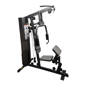
POWERHOUSE HOME GYM
IMPEX FITNESS PRODUCTS
14777 DON JULIAN RD., CITY OF INDUSTRY, CA 91746
Tel: (800) 999-8899 Fax: (626) 961-9966
www.impex-fitness.com
info@impex-fitness.com
WM-1501
Advertisement
Table of Contents

Related Manuals for Impex POWERHOUSE WM-1501


Summary of Contents for Impex POWERHOUSE WM-1501
- Page 1 Parts List Resistance Chart Warranty Ordering Parts Model WM-1501 Retain This Manual for Reference 06-02-03 OWNER'S MANUAL POWERHOUSE HOME GYM WM-1501 IMPEX FITNESS PRODUCTS 14777 DON JULIAN RD., CITY OF INDUSTRY, CA 91746 Tel: (800) 999-8899 Fax: (626) 961-9966 www.impex-fitness.com info@impex-fitness.com...
-
Page 2: Table Of Contents
WARRANTY...…………. 19 ORDERING PARTS...………… 19 BEFORE YOU BEGIN Thank you for selecting the POWERHOUSE WM-1501 HOME GYM by IMPEX FITNESS PRODUCTS. For your safety and benefit, read this manual carefully before using the machine. As a manufacturer, we are committed to provide you complete customer satisfaction. If you have any questions, or find there are missing or damaged parts, we guarantee you complete satisfaction through direct assistance from our factory. -
Page 3: Important Safety Notices
PHYSICIAN. THIS IS ESPECIALLY IMPORTANT FOR INDIVIDUALS OVER THE AGE OF 35 OR PERSONS WITH PRE-EXISTING HEALTH PROBLEMS. READ ALL INSTRUCTIONS BEFORE USING ANY FITNESS EQUIPMENT. IMPEX INC. ASSUMES NO RESPONSIBILITY FOR PERSONAL INJURY OR PROPERTY DAMAGE SUSTAINED BY OR THROUGH THE USE OF THIS PRODUCT. -
Page 4: Hardware Pack
HARDWARE PACK... - Page 5 HARDWARE PACK...
- Page 6 HARDWARE PACK...
-
Page 7: Assembly Instructions
ASSEMBLY INSTRUCTION Tools Required Assembling the Machine: Two Adjustable Wrenches, two Allen Wrenches, and one Philips Screwdriver. NOTE: It is strongly recommended this machine to be assembled by two or more people to avoid possible injury. STEP 1 (See Diagram 1) A.) Attach the Front Vertical Frame (#3) to the Main Base Frame (#8). - Page 8 STEP 2 (See Diagram 2) A.) Slide the 9 Weight Plates (#29) onto the Guide Rods (#20). Align the holes of the Weight Plates. Insert the Selector Rod (#13) through the center hole. Use a L-shaped Pin (#30) to select the number of plates. B.) Slide the Selector Stem (#28) onto the Guide Rods.
- Page 9 STEP 3 (See Diagram 3) A.) Attach the Front Press Base (#11) to the Upper Frame (#4). Secure it with one Long Axle (#43), two Ø ¾” Washers (#80), and two M10 Aircraft Nuts (#82). B.) Attach the Right Butterfly (#6) to the Front Press Base. Secure it with one M6 x 1 5/8” Hex Bolt (#75), Lock Ring (#37), and M6 Aircraft Nut (#83).
- Page 10 STEP 4 (See Diagram 4) A.) Attach the Main Seat Support (#1) to the Front Vertical Frame (#3). Secure it with two M10 x 3 ½” Carriage Bolts (#76), one 4 ¾” x 2” Bracket (#24), two M10 Aircraft Nuts (#82). B.) Attach the Leg Developer (#7) to the bracket on the Main Seat Support.
-
Page 11: Cable Loop Diagram
CABLE LOOP DIAGRAM... - Page 12 STEP 5 (See Diagram 5 & Cable Loop Diagram) A.) Attach the 131” Upper Cable (#31) to the opening at the front of the Upper Frame (#4). Note: The Ball Stopper on the cable should be underneath the Frame. B.) Attach a Pulley (#60) to the open bracket. Secure it with one M10 x 1 ¾” Allen Bolt (#69), two Ø...
- Page 13 DIAGRAM 5...
- Page 14 STEP 6 (See Diagram 6 & Cable Loop Diagram) A.) Attach one end of the 119” Butterfly Cable (#33) to the hook on the Right Butterfly (#6). B.) Draw the Cable to the right Swivel Pulley Bracket (#18). C.) Attach a Pulley to the bracket. Secure it with one M10 x 1 ¾” Allen Bolt (#69), two Ø ¾” Washers (#80), and one M10 Aircraft Nut (#82).
- Page 15 STEP 7 (See Diagram 7 & Cable Loop Diagram) A.) Attach the 128” Lower Cable (#32) to the open bracket on the bottom of the Leg Developer (#7). B.) Attach a Pulley to the bracket. Secure it with one M10 x 1 ¾” Allen Bolt (#69), two Ø ¾”...
- Page 16 DIAGRAM 7...
- Page 17 STEP 8 (See Diagram 8) A.) Attach a Short Chain (#46) to the Upper Cable (#31) by using a C-clip (#50). Attach the Lat Bar (#14) to the Chain by using another C-clip. Adjust the length of the Chain to obtain desired Lat Bar exercise. B.) Attach a Long Chain (#45) to the Lower Cable (#32) by using a C-clip (#50).
-
Page 18: Parts List
PARTS LIST KEY NO. DESCRIPTION Main Seat Support Rear Base Frame Front Vertical Frame Upper Frame Left Butterfly Right Butterfly Leg Developer Main Base Frame Butterfly Pulley Bracket Arm Curl Stand Front Press Base Front Press Handle Selector Rod Lat Bar Arm Curl Handle Double Floating Pulley Bracket Crossed Double Floating Pulley Bracket1... -
Page 20: Warranty
IMPEX Customer Service Department at 1-800-999-8899. All freights on products returned to IMPEX must be prepaid by the customer. This warranty does not extend to any product or damage to a product caused by or attributable to freight damage, abuse, misuse, improper or abnormal usage or repairs not provided by an IMPEX authorized service center or for products used for commercial or rental purposes.