Monogram ZGU384L Technical Service Manual
30- and 36-in. stainless steel gas cooktops
Hide thumbs
Also See for ZGU384L:
- Owner's manual (36 pages) ,
- Installation instructions manual (36 pages) ,
- Owner's manual (32 pages)

Related Manuals for Monogram ZGU384L


Summary of Contents for Monogram ZGU384L
-
Page 1: Stainless Steel
GE Consumer & Industrial Technical Service Guide October 2006 30- and 36-in. Monogram Stainless Steel Gas Cooktops ZGU384L ZGU384N ZGU385L ZGU385N 31-9144 GE Appliances General Electric Company Louisville, Kentucky 40225... - Page 2 If grounding wires, screws, straps, clips, nuts, or washers used to complete a path to ground are removed for service, they must be returned to their original position and properly fastened. GE Consumer & Industrial Technical Service Guide Copyright © 2006 All rights reserved.
-
Page 3: Table Of Contents
Table of Contents Burners ....................................21 Burner Base ..................................16 Burner Valves ..................................20 Care and Cleaning ................................11 Component Locator Views ............................14 Cooktop Components ..............................16 Features ....................................9 Gas Type Conversion ..............................25 High Altitude Conversion ............................... 28 Ignitor ..................................... -
Page 4: Introduction
Introduction The GE Monogram 30- and 36-in. Stainless Steel Gas Cooktops have the following features: • Stainless steel cooktop surface • Continuous interlocking porcelainized cast-iron grates • Stainless steel tactile grip control knobs with "burner on" indicator lights • Dual flame sealed cooktop burners with 140°F simmer selection •... -
Page 5: Installation
Installation WARNING: Before beginning the installation, Note: The complete installation instructions are switch power off at the service panel and lock the inclosed with the Use and Care Manual. Carefully service disconnecting means. When the service read and follow these instructions. disconnecting means cannot be locked, securely fasten a warning tag to the service panel. - Page 6 Model ZGU385 DIMENSIONS AND CLEARANCES 1. Overall cooktop dimensions: 3. Make sure the wall coverings, countertop and cabinets around the cooktop can withstand heat 36-3/4″ (up to 200°F) generated by the cooktop. 21-3/16″ 13″ max. deep at center 3-1/2″ 36″ 30″...
- Page 7 Gas Supply Electric Supply Cooktops are shipped from the factory set for This cooktop features pilotless electronic ignition either natural or LP gas, and are reversible with the for energy savings and reliability. It operates on a included required parts. For operation above 5,000 120 volt, 60 Hz power supply.
-
Page 8: Nomenclature
Nomenclature Model Number Z G U 3 8 5 N S M I S S Brand Exterior Color Z = Monogram SS = Stainless Steel Indicator for Engineering and Product Service only Configuration U = Cooktop Model Year Designator Model Designator Ignition System Designates features –... -
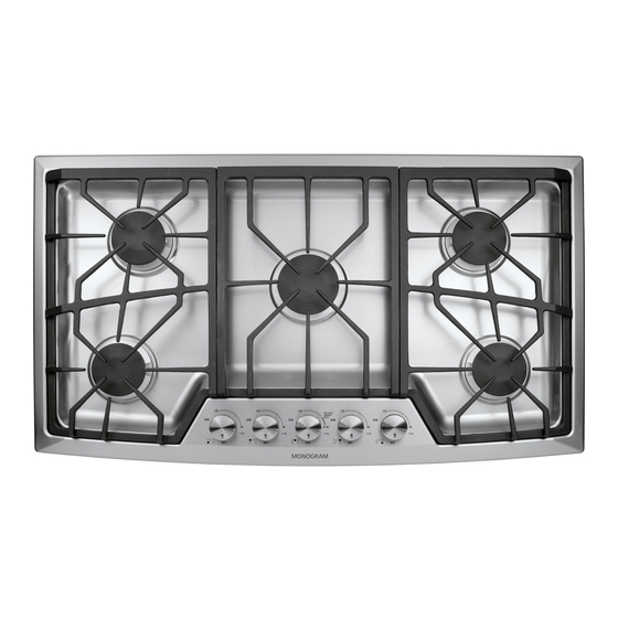
Page 9: Features
Features ZGU384L and ZGU384N Features (Throughout this manual, features and appearance may vary.) ZGU384 – 30" Gas Cooktop Dual-Flame Spillproof Burners—HighOutput Dual-Flame Spillproof Burners—X-High Output Tactile-touch Control Knobs (One For Each Surface Burner) Burner “ON” Indicator Lights (One On Each Control Knob) - Page 10 Electronic In case of a power outage, you can light the The surface burners are lit by electronic ignition. surface burners on your cooktop with a match. ignition & All burner igniters make clicking sounds and Hold a lighted match to the burner; then turn the spark even when only a single burner is being relight knob to the HIGH position.
-
Page 11: Care And Cleaning
Dual-flame All burners on your cooktop have two rows of flames. These dual-flame burners have a simmer spill-proof (lower) flame and a main (upper) flame. burners When a burner is turned on, the simmer flame will always light and stay on. Simmer Flame Simmering: The simmer (SIM) setting will use only the lower flames. - Page 12 Burner grates To get rid of burned-on food, place the grates in Cast-iron burner grates should be washed regularly and especially after spillovers. Wash a covered container or plastic bag. Add 1/4 cup them in hot, soapy water and rinse with clean of ammonia and let them soak for 30 minutes.
- Page 13 Dual-flame To remove the burner parts: 1. Replace the burner head on top of the burner base, making sure that the hole in the burner spill-proof NOTE: Before removing the burner parts, head is properly aligned with the electrode in burners (cont.) remember their size and location.
-
Page 14: Component Locator Views
Component Locator Views Model ZGU384 Burner Cap Burner Head Ignitor Maintop Burner Box Model ZGU384 (maintop and top heat barrier removed) Manifold Spark Module Transformer Burner Burner Indicator Light Assembly Burner Valve (1 of 4) Burner Burner Ignitor and Light Switch (1 of 4) (Continued next page) –... - Page 15 Model ZGU385 Ignitor Burner Cap Burner Head Maintop Burner Box Model ZGU385 (maintop and top heat barrier removed) Transformer Spark Module Burner Burner Manifold Burner Burner Burner Indicator Light Assembly Ignitor and Light Switch (1 of 5) Burner Valve (1 of 5) –...
-
Page 16: Burner Base
Cooktop Components WARNING: Disconnect electrical power to the Caution: When removing the wire from the igniter, cooktop and turn OFF gas at the main valve before make sure you do not damage the heat shrink performing any removal procedures. insulation on the wire. If damaged, repair the wire insulation with fiberglass tape. -
Page 17: Ignitor
Ignitor Maintop Note: The following describes the procedure to Note: Maintop removal is required to access: remove a single ignitor. The procedure to remove • Indicator light assembly the remaining ignitors is identical. • Ignitor and light switch assembly To remove the ignitor: •... -
Page 18: Indicator Light Assembly
Remove the 2 Phillips-head screws that attach each circuit board and insulator to the light harness bracket. Slide the wire guide out of the bracket, disconnect the wire harness and the strain relief, and remove the indicator light harness (part# WB18T10383 for model ZGU384 or part # WB18T10384 for model # ZGU385). -
Page 19: Ignitor And Light Switch Assembly
Model ZGU384 Ignitor and Light Switch Assembly Each burner utilizes an ignitor switch and a light switch combined in a single unit. The ignitor and light switches are all wired to a single harness. When a burner knob is turned to the ON position, Transformer the ignitor switch closes and activates the spark Wire Harness... -
Page 20: Burner Valves
Remove the four ¼-in. hex-head screws that Burner Valves attach the valve access plate to the bottom of the burner box. Note: The following describes the procedure to remove a single burner valve. The procedure to remove the remaining valves is identical. To remove the burner valve on model ZGU385: Remove the maintop. -
Page 21: Burners
To remove the burner valve on model ZGU384: Burners Remove the maintop. (See Maintop Note: The following describes the procedure to remove the X-High Output burner. Remove the indicator light assembly. (See Indicator Light Assembly To remove the X-High Output burner: Lift the ignitor switch from the burner valve Note: Because the X-High Output burner has a stem. -
Page 22: Spark Module
Note: Excluding the X-High Output burner the Spark Module following describes the procedure to remove a single burner. The procedure to remove the To remove the spark module: remaining burners is identical. Remove the regulator. To remove the burner: Remove the maintop. (See Maintop Remove the maintop. -
Page 23: Manifold
Transformer Manifold To remove the transformer: To remove the manifold from Model ZGU385: Remove the maintop. (See Remove the regulator. Maintop Remove the top heat barrier by lifting it out of Remove the maintop. (See Maintop the burner box. Remove the top heat barrier by lifting it out of Disconnect the transformer wire harness. - Page 24 Remove the -in. nut and separate the Hi-Lo gas tube from the center, left front, and left rear burner valves. Remove the -in. nut and separate the Simmer gas tube from the center, left front, and left rear burner valves. Remove the seven ¼-in.
-
Page 25: Gas Type Conversion
Models This will help to prevent the possibility ZGU384L and ZGU385L are shipped from the factory that some may not be replaced. set for liquefied petroleum (LP) gas operation. If Burner A. - Page 26 IMPORTANT: Orifices must be located exactly as shown. Carefully read and observe each orifice label for correct location. Model ZGU385 Model ZGU384 SIMMER SIMMER ORIFICES ORIFICES MAIN MAIN ORIFICES ORIFICES 138XN 84XL 108XL 190XN 84XL 148XN – 26 –...
- Page 27 ADJUST BURNER FLAMES • If the flames were too small or fluttered, open the valve more than the original setting. A. Turn all burners on highest setting and check the flames. • If the flames blew away from the burner, close the valve They should be blue (no yellow tipping) when using more than the original setting.
-
Page 28: High Altitude Conversion
REPLACE ALL BURNER ORIFICES High Altitude Conversion A. TO REMOVE THE BURNER PARTS: Remove the burner caps and main burner head (brass). GAS SUPPLY NOTE: Do not remove the burner base. Measure the incoming gas pressure to the regulator. B. TO REPLACE BURNER ORIFICES: With the installation of this conversion kit, the cooktop should operate on LP gas at 10”... -
Page 29: Troubleshooting
Troubleshooting Problem Possible Causes What to Do Burner flames are very Incorrect gas being used. • Check for correct gas supply. large, yellow, or yellow- tipped The combustion quality of • Use the illustrations below to determine if the burner burner flames needs to be flames are normal. -
Page 30: Ignitor Switch Test
Ignitor Switch Test Disconnect power to the cooktop. Turn on each burner separately and check for 0 resistance between the red wire on the transformer wire harness and the corresponding SW terminal on the spark module wire harness. Burner Location Wire Colors Center Transformer Red to... -
Page 31: Schematics And Wiring Diagrams
Schematics and Wiring Diagrams WARNING: Disconnect electrical power before servicing. Caution: Label all wires prior to disconnection. Wiring errors can cause improper and dangerous operation. Verify operation after servicing. ZGU384 Schematic (Continued next page) – 31 –... - Page 32 ZGU385 Schematic (Continued next page) – 32 –...
- Page 33 ZGU384 Wiring Diagram (Continued next page) – 33 –...
- Page 34 ZGU385 Wiring Diagram – 34 –...
-
Page 35: Warranty
GE Authorized Servicer is not available, you may be responsible for a trip charge or you may be required to bring the product to an Authorized GE Service location for service. In Alaska the warranty is the same except that it is LIMITED because you must pay to ship the product to the service shop or for the service technician’s travel costs to your home.