Table of Contents
Advertisement
NOTE:
Please read all instructions
carefully before using this
product
Table of Contents
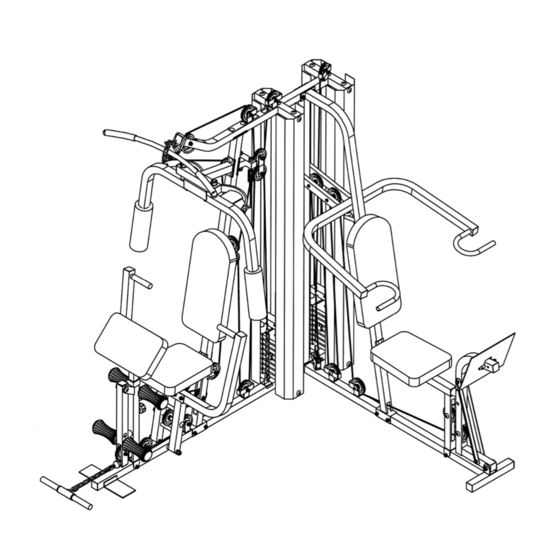
MARCY CORNER GYM
Safety Notice
CR 5
Resistance Chart
Model
MWB CR 5
Retain This
Manual for
Reference
9-20-02
OWNER'S
IMPEX FITNESS PRODUCTS
MANUAL
14777 DON JULIAN RD., CITY OF INDUSTRY, CA 91746
Tel: (800) 999-8899 Fax: (626) 961-9966
www.impex-fitness.com
info@impex-fitness.com
Advertisement
Table of Contents

Related Manuals for Impex MARCY CR 5


Summary of Contents for Impex MARCY CR 5
- Page 1 Safety Notice CR 5 Hardware Identifier Assembly Instruction Parts List Resistance Chart Warranty Ordering Parts Model MWB CR 5 Retain This Manual for Reference 9-20-02 OWNER'S IMPEX FITNESS PRODUCTS MANUAL 14777 DON JULIAN RD., CITY OF INDUSTRY, CA 91746 Tel: (800) 999-8899 Fax: (626) 961-9966 www.impex-fitness.com...
-
Page 2: Table Of Contents
ORDERING PARTS... 25 BEFORE YOU BEGIN Thank you for selecting the MARCY CR5 CORNER GYM by IMPEX FITNESS PRODUCTS. For your safety and benefit, read this manual carefully before using the machine. As a manufacturer, we are committed to provide you complete customer satisfaction. -
Page 3: Important Safety Notices
THIS IS ESPECIALLY IMPORTANT FOR INDIVIDUALS OVER THE AGE OF 35 OR PERSONS WITH PRE-EXISTING HEALTH PROBLEMS. READ ALL INSTRUCTIONS BEFORE USING ANY FITNESS EQUIPMENT. IMPEX INC. ASSUMES NO RESPONSIBILITY FOR PERSONAL INJURY OR PROPERTY DAMAGE SUSTAINED BY OR THROUGH THE USE OF THIS PRODUCT. -
Page 5: Assembly Instructions
Tools Required Assembling the Machine: Two Adjustable Wrenches and Allen Wrenches NOTE: It is strongly recommended two or people assembling this machine to avoid possible injury. STEP 1 (See Diagram 1) A.) Place the Right Base Frame (#46) and Left Base Frame (#87) on the floor, at a right angle to each other. - Page 6 STEP 2 (See Diagram 2) A.) Attach the Right Vertical Beam (#21) to the Right Base Frame (#46). Secure it with two M10 x 2 ¾” Carriage Bolts (#17), B.) Attach the Right Seat Support (#49) to the Right Vertical Beam (#21). Secure it with one Bracket (#7), two M10 x 2 ¾”...
- Page 7 STEP 3 (See Diagram 3) A.) Slide two 2 ½” Rubber Bumpers (#58) onto two Chromed Guide Rods (#58). Insert the two Guide Rods into the holes on the Right Base Frame (#46). Slide the Selector Stem (#67) onto the two Guide Rods (#22). Slide the Selector Stem over the Selector Rod (#69). Secure the Selector Rod to the Selector Stem with two M10 x 1”...
- Page 8 DIAGRAM 3...
- Page 9 STEP 4 (See Diagram 4) A.) Attach the Front Press Base (#97) to the Right Base Frame (#46). Secure it with a 9 ¼” Front Press Axle (#60), two B.) Attach the Front Press Frames (#63) to the Front Press Base. Secure it with four M10 x 2 ¾” Carriage Bolts (#17), ¾”...
- Page 10 STEP 5 (See Diagram 5) A.) Attach the Butterfly Support Frame (#18) to the front of Right Vertical Beam (#21). Attach the Butter Pulley Support (#74) to the back of Right Vertical Beam. Align the holes. Secure them together with two M10 x 2 ¾” Carriage Bolts (#17), (#5).
- Page 11 STEP 6 (See Diagram 6) A.) Attach the Vertical Press Frame (#78) to the Rear Vertical Beam (#50). Secure it with a M10 x 4 7/8” Vertical Press Axle (#81), two ¾” Washers (#6), and two M10 x 1” Allen Bolts (#56). B.) Place the Vertical Press Frame rest onto the 1 ½”...
- Page 12 CABLE LOOP DIAGRAM...
- Page 13 STEP 7 (Upper Cable Loop & Diagram 7) A.) Attach the 108” Upper Cable (#93) to the front opening on the Upper Frame (#8). Attach a Pulley (#79) to the opening. Secure it with one M10 x 2 ½” Allen Bolt (#10), two Pulley Bushings (#11), and one M10 Aircraft Nut (#5).
- Page 14 DIAGRAM 7...
- Page 15 STEP 8 (See Butterfly Cable Loop & Diagram 8) A.) Attach the 83” Butterfly Cable (#95) to the slot on the back of Left Butterfly (#20). Draw the Cable through the slot then to the open left Swivel Pulley Bracket (#72). B.) Attach a Pulley (#79) to the bracket.
- Page 16 DIAGRAM 8...
- Page 17 STEP 9 (See Front Press Cable Loop & Diagram 9) A.) Attach the 247” Front Press Cable (#94) to the lower opening on the Leg Developer (#40). B.) Attach a Pulley (#79) to the opening. Secure it with one M10 x 2 ½” Allen Bolt (#10), two Pulley Bushings (#11), and one M10 Aircraft Nut (#5).
- Page 18 DIAGRAM 9...
- Page 19 STEP 10 (See Leg Press Cable Loop & Diagram 10) A.) Attach one end of the 82” Leg Press Cable (#96) to the open slot on the back of the Leg Press Frame (#84). Secure it with one M10 x 2 ½” Allen Bolt (#10), two and one M10 Aircraft Nut (#5).
- Page 20 DIAGRAM 10...
- Page 21 STEP 11 (See Diagram 11) A.) Place a Seat Pad (#29) onto the Left Seat Support (#92). Secure it with two M8 x 2 1/8” Allen Bolts (#25) and 5/8” Washers (#24). B.) Attach a Backrest Board (#28) to the Left Vertical Beam (#77). Secure it with two M8 x 2 1/8” Allen Bolts (#25) and C.) Attach the Leg Press Plate (#76) onto the Leg Press Frame (#84).
- Page 22 STEP 12 (See Diagram 12) A.) Place a Seat Pad (#29) onto the Right Seat Support (#49). Secure it with two M8 x 2 1/8” Allen Bolts (#25) and B.) Attach a Backrest Board (#28) to the Right Vertical Beam (#21). Secure it with two M8 x 2 1/8” Allen Bolts (#25) and C.) Insert two Foam Roll Tubes (#36) halfway through the holes on the Right Seat Support (#49) and Leg Developer (#40).
- Page 23 STEP 13 (See Diagram 13) A.) Securely tighten all the nuts and bolts previously installed. B.) Before putting the Weight Plates on, now move the machine to the corner of the room or place where you will use the machine. C.) Lift up the Selector Rod and install one stack of 19 Weight Plates (#66).
-
Page 24: Parts List
PARTS LIST KEY NO. DESCRIPTION Lat Bar Grip Lat Bar Chain C-clip M10 Aircraft Nut ¾” Washer Bracket Upper Frame 1 ¾” Square End Cap M10 x 2 ½” Allen Bolt Pulley Bushing M6 x 1 5/8” Hex Bolt 1 3/8” Lock Ring M6 Aircraft Nut Butterfly Axle Sleeve 1 ½”... -
Page 25: Resistance Chart
WEIGHT RESISTANCE CHART Station Low Pulley Lat Pull Butterfly Leg Press Front Press Vertical Press Station Low Pulley 150 162 174 186 198 210 222 234 246 258 Lat Pull 140 150 160 170 180 190 200 210 220 230 Butterfly 133 146 159 172 185 198 211 224 237 250 Leg Press... -
Page 26: Warranty
IMPEX Customer Service Department at 1-800-999-8899. All freights on products returned to IMPEX must be prepaid by the customer. This warranty does not extend to any product or damage to a product caused by or attributable to freight damage, abuse, misuse, improper or abnormal usage or repairs not provided by an IMPEX authorized service center or for products used for commercial or rental purposes.