Table of Contents
Advertisement
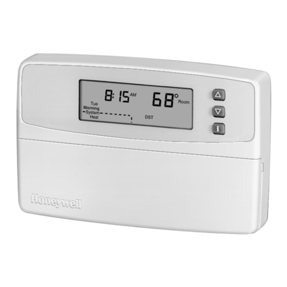
Honeywell/36
Programmable Thermostat
OWNER'S GUIDE
Seven Day
Programmable Heat and/or Cool
Low Voltage (20 to 30 Vac) Thermostat and Wallplate
Model CT3600
Para pedir estas instrucciones en español,
llame al 1-800-468-1502 por 69-0939S.
Pour obtenir ce mode d'emploi en français,
69-0939-1
composer le 1-800-468-1502 pour 69-0939F.
1
69-0939—1
Advertisement
Table of Contents

Related Manuals for Honeywell 36


Summary of Contents for Honeywell 36
-
Page 1: Programmable Thermostat
Honeywell/36 Programmable Thermostat OWNER’S GUIDE Seven Day Programmable Heat and/or Cool Low Voltage (20 to 30 Vac) Thermostat and Wallplate Model CT3600 Para pedir estas instrucciones en español, llame al 1-800-468-1502 por 69-0939S. Pour obtenir ce mode d’emploi en français, 69-0939-1 composer le 1-800-468-1502 pour 69-0939F. - Page 2 We invite you to spend a few minutes reading this manual. You’ll find it answers many of the questions that will arise as you become familiar and comfortable with your Honeywell thermostat, the state of the art in home comfort controls.
- Page 3 TYPICAL LOCATION OF A MERCURY disposal of this control, or of an old SWITCH IN A THERMOSTAT control containing mercury in a sealed M10614 tube. If you have questions, call Honeywell Inc. at 1-800-468-1502. 69-0939—1...
-
Page 4: Table Of Contents
TABLE OF CONTENTS Step 1. Prepare for Installation ..............5 Step 2. Remove Old Thermostat ............... 6 Step 3. Mount Thermostat Wallplate ............8 Step 4 Wire Wallplate Terminals ............... 9 Step 5. Install the Batteries ............... 13 Step 6. Set Fan Operation Switch ............. 14 Step 7. -
Page 5: Step 1. Prepare For Installation
Multistage Heat Oil-Fired Boilers Pumps/Multistage Oil-Fired Furnace Equipment Electric Furnace Not compatible with any 120/240 volt circuit. Compatible with 2-wire Honeywell and Taco zone valves. Not compatible with 3-wire zone valves or 2-wire White Rodgers no. 1361 zone valves. 69-0939—1... -
Page 6: Step 2. Remove Old Thermostat
STEP 2. REMOVE OLD THERMOSTAT Test to make certain that your heating and Loosen screws holding thermostat to cooling systems are working properly. If subbase, wallplate or wall, and lift away. either does not work, contact your local heating/air conditioning dealer. To avoid Disconnect wires from old thermostat or compressor damage, do not operate the subbase. - Page 7 If you C or C1 clock terminals? would like information about which program- If you are replacing a Honeywell mable thermostats will work with your Chronotherm® Clock Thermostat, you may system, call Honeywell Customer Assistance find one or two wires that go to the C or C1 Center at 1-800-468-1502.
-
Page 8: Step 3. Mount Thermostat Wallplate
STEP 3. MOUNT THERMOSTAT WALLPLATE Position wallplate on wall. Level the wallplate for appearance if desired. Use a WALL pencil to mark the two mounting holes that best fit the application. WIRES THROUGH WALL Remove wallplate from wall, and drill 3/16 inch holes in wall (if drywall) as marked. -
Page 9: Step 4 Wire Wallplate Terminals
STEP 4. WIRE WALLPLATE TERMINALS NOTE: All wiring must comply with local Loosen the terminal screws and slip each codes and ordinances. If unsure wire beneath its matching terminal. Either about household wiring procedures, straight or wraparound wiring connections call your local heating/air condition- are acceptable (see illustration). - Page 10 4-WIRE HEAT/COOL 2-WIRE HEAT-ONLY (JUMPER INTACT) (JUMPER INTACT) THERMOSTAT THERMOSTAT RC O W Y RC O W Y HEATING HEATING COOLING RELAY OR RELAY OR CONTACTOR VALVE COIL RELAY VALVE COIL COIL 1 POWER SUPPLY. PROVIDE DISCONNECT MEANS 1 POWER SUPPLY. PROVIDE DISCONNECT MEANS AND OVERLOAD PROTECTION AS REQUIRED.
- Page 11 3-WIRE HEAT ONLY WITH FAN 4-WIRE SINGLE-STAGE HEAT PUMP (JUMPER INTACT) (JUMPER INTACT) THERMOSTAT THERMOSTAT RC O W Y RC O W Y HEATING RELAY OR RELAY HEAT VALVE COIL COMPRESSOR CHANGEOVER CONTACTOR VALVE COOL CHANGEOVER RELAY VALVE 1 POWER SUPPLY. PROVIDE DISCONNECT MEANS AND OVERLOAD PROTECTION AS REQUIRED.
- Page 12 5-WIRE HEAT/COOL WITH DAMPER 5-WIRE HEAT/COOL (JUMPER INTACT) (JUMPER REMOVED) THERMOSTAT RC O W Y RC O W Y HEAT HEAT COMPRESSOR HEATING COOLING DAMPER RELAY CONTACTOR RELAY OR CONTACTOR RELAY VALVE COIL COIL COOL RELAY DAMPER 1 POWER SUPPLY. PROVIDE DISCONNECT MEANS AND OVERLOAD PROTECTION AS REQUIRED.
-
Page 13: Step 5. Install The Batteries
STEP 5. INSTALL THE BATTERIES IMPORTANT If you insert new batteries within 20 to 30 Three AA alkaline batteries are seconds of removing the old ones, you will included with the thermostat. not have to reset the current time. However, if Batteries must be installed for the display is blank, the batteries are dead or programming and operation of the... -
Page 14: Step 6. Set Fan Operation Switch
IMPORTANT STEP 6. SET FAN Although the thermostat has a low battery indicator, replace the OPERATION SWITCH batteries once a year to prevent leakage and to prevent the The thermostat fan operation switch, labeled thermostat and heating/cooling FUEL SWITCH is factory set in the F position. system from shutting down due to This is the correct setting for most systems. -
Page 15: Step 7. Mount The Thermostat
STEP 7. MOUNT THE STEP 8. CUSTOMIZING THERMOSTAT YOUR THERMOSTAT ENGAGE TABS AT TOP OF THERMOSTAT AND WALLPLATE. The thermostat can be customized to match your heating/cooling system and your display preferences. See pages 18 and 19 for available options. The thermostat comes factory set to the most common settings: °F temperature display, —... - Page 16 You can change any of these settings by • the time you want the comfort temperature pressing and holding the Information established. and both keys until the numbers 4 and 6 are displayed. All the display The thermostat displays In Recovery, segments will appear for about 3 seconds changes the setpoint and turns on the system before the numbers 4 and 6 appear.
- Page 17 Smart Response System Operating in Comfort Mode 68°F Room Morning Recovery System Heat Continues Room 66°F Heat Night Recovery System Recovery Heat Begins Room 64°F Heat Night Recovery System System Operating in Heat Energy Savings Mode 62°F Room Night System Heat 5:00 5:30...
- Page 18 The following table shows the numbers that will be displayed and what your choices are. Number Displayed (Press Other Choices (Press key to change) Time Factory-Setting Actual Select to change) Setting Display Description Display Description Heating Gas or oil forced air 1, 3 or 9 1—radiant floor heat cycle rate a...
- Page 19 Number Displayed (Press Other Choices Time (Press key to change) Factory-Setting Actual Select to change) Setting Display Description Display Description Tempera- Temperature is Temperature is displayed in °F displayed in °C ture format Clock Time is displayed in Time is displayed in format 12-hour format 24-hour (military time)
-
Page 20: Step 9. Programming
—the time period you can set for an STEP 9. PROGRAMMING Daytime energy-saving temperature while you are away at work or school. (This will be The keyboard is located behind the thermo- a lower temperature in the heating stat cover with three frequently used keys by season and a higher temperature the display. - Page 21 Personal Programming Table Sunday Monday Tuesday Wednesday Thursday Friday Saturday Period Default Setting (Sun) (Mon) (Tue) (Wed) (Thu) (Fri) (Sat) Morning Time (6:00 AM) Heat a (70°F/21°C) Cool b (78°F/25.5°C) Daytime Time (8:00 AM) Heat a (62°F/16.5°C) Cool b (85°F/29.5°C) Evening Time (6:00 PM) Heat a (70°F/21°C)
- Page 22 IMPORTANT Setting the Current Day and Time Always press the keys with your Set Current Press and release then until Day/Time fingertip or similar blunt tool. Sharp the current day is displayed. (Sun = Sunday, instruments like pens and pencil Mon = Monday, Tue = Tuesday, Wed = points can damage the touchpad.
- Page 23 (The setpoint temperature range is 40 to 90°F Press when all the days are Program (7 to 31°C) for heating and 45 to 99°F (9 to programmed. Heat/Cool 37°C) for cooling.) Press to switch to Settings your other system temperature setpoint. Copying a Day NOTE: The program times are the same for NOTE: Your thermostat must be in the...
-
Page 24: Step 10. Operating Your Thermostat
Clearing Program Period STEP 10. OPERATING YOUR THERMOSTAT NOTE: Your thermostat must be in the program mode to use the clear feature. Setting Temporary Temperatures Evening Night Daytime Press Morning Changing Temperature Setting Until The Next Press until the desired day is Program Period displayed. - Page 25 (Example: Evening = thermostat will stop the Changing Temperature Setting Indefinitely Hold at the Evening period start time.) Move the System switch to heat or cool. Press key to adjust the temperature Press then key to change Hold Temp setting, if desired. (Example: Heat 54° = your setting, if desired.
- Page 26 IMPORTANT Using Usage Feature If the Hold needs to be canceled Press once to display the minutes Usage before the designated time, press that the heating or cooling system has been to return to your program. Program operating for the current day. Press Usage second time, within 10 seconds, to display Using Daylight Savings Time Feature...
-
Page 27: Step 11. Setting The Fan And System Switches
STEP 11. SETTING THE FAN AND SYSTEM SWITCHES First set the fan switch. Fan On: The fan runs continuously. Use for Auto improved air circulation or for more efficient central air cleaning. (In a heat-only system, fan runs continuously only if fan relay is connected to the G thermostat terminal.) Fan Auto: Normal setting for most homes. -
Page 28: Troubleshooting Guide
TROUBLESHOOTING GUIDE I F … THEN… Display will not • Check that the batteries are installed correctly and fresh. come on. • Check if the thermostat is mounted and latched on the wallplate—mount and latch the thermostat on the wallplate. Temperature settings •... - Page 29 I F … THEN… Cooling will not • Check that cool setpoint is below room temperature. come on. • Check if the circuit breaker is tripped—reset the circuit breaker. • Check if the system switch at the equipment is in the Off position—set to On position. •...
- Page 30 If additional assistance is needed, call NOTICE: This equipment is a Class B digital Honeywell Customer Assistance toll-free at apparatus, which complies with Canadian 1-800-468-1502, Monday-Friday, 7:00 a.m. - Radio Interference Regulations, 5:30 p.m., Central time.
-
Page 31: Limited One-Year Warranty
Honeywell warrants this product, excluding battery, to be free from defects in the workmanship or materials, under normal use and service, for a period of one (1) year from the date of purchase by the consumer. If, at any time during the warranty period, the product is defective or malfunctions, Honeywell shall repair or replace it (at Honeywell’s option) within a reasonable period of time. - Page 32 P.O. Box 524 North York, Ontario Minneapolis, MN 55408-0524 M2H 3N7 Printed in U.S.A. on recycled 69-0939—1 Rev. 11-97 J.H. paper containing at least 10% 69-0939—1 Copyright © 1997 Honeywell Inc. All Rights Reserved ® U.S. Registered Trademark post-consumer paper fibers.