Icom IC-V8 Instruction Manual
Icom marine radio user manual
Hide thumbs
Also See for IC-V8:
- Instruction manual (80 pages) ,
- Service manual (31 pages) ,
- Service manual (6 pages)
Table of Contents
Advertisement
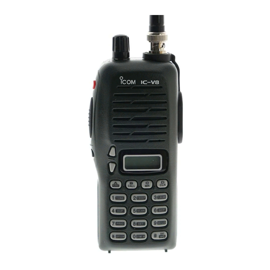
INSTRUCTION MANUAL
VHF TRANSCEIVER
i V 8
This device complies with Part 15 of the FCC rules. Oper-
ation is subject to the following two conditions: (1) This de-
vice may not cause harmful interference, and (2) this
device must accept any interference received, including in-
terference that may cause undesired operation.
Advertisement
Table of Contents

Related Manuals for Icom IC-V8


Summary of Contents for Icom IC-V8
- Page 1 INSTRUCTION MANUAL VHF TRANSCEIVER i V 8 This device complies with Part 15 of the FCC rules. Oper- ation is subject to the following two conditions: (1) This de- vice may not cause harmful interference, and (2) this device must accept any interference received, including in- terference that may cause undesired operation.
-
Page 2: Safety Training Information
The radio is transmitting when the “TX indicator” is lit. You can cause the radio to transmit by pressing the “PTT” switch. • ALWAYS use Icom authorized accessories (antennas, batter- ies, belt clips, speaker/mics, etc.). Use of unauthorized acces- sories can cause the FCC RF exposure compliance... - Page 3 • ALWAYS keep the antenna at least 2.5 cm (1 inch) away from the body when transmitting, and only use the Icom belt-clips which are listed in this manual when attaching the radio to your belt, etc. To provide the recipients of your transmission the best sound quality, hold the antenna at least 5 cm (2 inches) from your mouth, and slightly off to one side.
-
Page 4: Foreword
FOREWORD Thank you for purchasing the IC-V8 FM transceiver. This trans- ceiver is designed for those who require quality, performance and outstanding reliability under the most demanding condi- tions. IMPORTANT READ ALL INSTRUCTIONS carefully and completely before using the transceiver. -
Page 5: Supplied Accessories
SUPPLIED ACCESSORIES Accessories included with the transceiver: q Antenna .........1 w Belt clip . -
Page 6: Precaution
PRECAUTION RWARNING! NEVER hold the transceiver so that the antenna is very close to, or touching exposed parts of the body, especially the face or eyes, while transmitting. The transceiver will perform best if the microphone is 5 to 10 cm (2 to 4 in) away from the lips and the transceiver is vertical. - Page 7 Otherwise, the bat- tery pack or installed Ni-Cd batteries will become exhausted. For USA only: Caution: Changes or modifications to this transceiver, not ex- pressly approved by Icom Inc., could void your authority to op- erate this transceiver under FCC regulations.
-
Page 8: Table Of Contents
TABLE OF CONTENTS SAFETY TRAINING INFORMATION ..... . .i–ii FOREWORD ......... .iii IMPORTANT . - Page 9 6 MEMORY PROGRAMMING ......25–27 ‘ General .........25 ‘...
-
Page 10: Panel Description
PANEL DESCRIPTION ‘ ‘ Switches, controls, keys and connectors q CONTROL DIAL [VOL] A Adjusts the audio level. B Selects the operating channel or adjusts the squelch level. • The function B is available when “dial” is assigned with [VOL] in INITIAL SET MODE w POWER SWITCH [POWER] Push for 1 sec. - Page 11 r SQUELCH SWITCH [SQL] Push and hold to force the squelch open and to adjust the squelch level with [Y]/[Z] keys. t UP/DOWN KEYS [Y Y ]/[Z Z ] A Selects the operating channel or adjusts the squelch level. B Adjusts the audio level. •...
- Page 12 PANEL DESCRIPTION D Key pad [name] Access to secondary function [A• FUNC Select the call channel. (p. 19) [B• CALL Selects a memory mode. (p. 19) [C• Selects VFO mode, aborts direct frequency input, or cancels scanning, etc. (pgs. 16, 31) [D•...
- Page 13 PANEL DESCRIPTION SECONDARY FUNCTION (After [A• ] is pushed) FUNC No function. No function. Entering into memory programming/editing mode. (p. 25) Programs/transfers VFO/memory or call channel contents into memory channel/VFO when pushed for 1 sec. (pgs. 25, 26) No function. Selects the subaudible tone function.
- Page 14 PANEL DESCRIPTION D Key pad (Continued) [name] Input digit “7” during frequency input, memory chan- nel selection, etc. (pgs. 16, 19) [7• PRIO Input digit “8” during frequency input, memory chan- nel selection, etc. (pgs. 16, 19) [8• Input digit “9” during frequency input, memory chan- nel selection, etc.
- Page 15 PANEL DESCRIPTION SECONDARY FUNCTION (After [A• ] is pushed) FUNC Starts the priority watch. (p. 33) Enters into the . (p. 46) SET MODE Toggles between high and low output power. (p. 18) Enters into the DTMF memory mode. (p. 28) Selects an optional pager or code squelch operation mode.
-
Page 16: Function Display
PANEL DESCRIPTION ‘ ‘ Function display q FUNCTION INDICATOR Appears while a secondary function is being accessed. w SKIP CHANNEL INDICATOR Appears when the selected memory channel is set as a “skip channel.” (p. 32) e DUPLEX INDICATOR Either “–” or “+” appears during repeater operation (p. 21). r TONE ENCODER INDICATOR Appears when tone encoder is in use. -
Page 17: Panel Description
o SIGNAL INDICATOR Appears when the channel is busy and shows receiving signal strength as below. Weak !0 LOW POWER INDICATOR Appears when low output power is selected. (p. 18) !1 KEY LOCK INDICATOR (p. 19) Appears when the key lock function is ON. !2 FREQUENCY READOUT Shows operating frequency, channel number or channel names, depending on display mode (p. -
Page 18: Accessories
ACCESSORIES ‘ ‘ Accessory attachment D Antenna Attach the antenna to the transceiver as il- lustrated at right. Keep the jack cover attached when jacks are not in use to avoid bad contacts. D Belt clip Attach the belt clip to the transceiver as illustrated below. To release the belt-clip To attach the belt-clip... -
Page 19: Battery Packs
‘ ‘ Battery pack replacement Before replacing the battery pack, push [POWER] for 1 sec. to turn the power OFF. • Push the battery release forward, then pull the battery pack upward with the transceiver fac- ing you. D D BATTERY PACKS BP-208* Operating periods are calculated under the following conditions;... -
Page 20: Battery Caution
BATTERY PACKS ‘ ‘ Battery caution • CAUTION! NEVER short the terminals of the battery pack (or charging terminals of the transceiver). Also, current may flow into nearby metal objects such as a necklace, so be careful when plac- ing battery packs (or the transceiver) in handbags, etc. Simply carrying with or placing near metal objects such as a neck- lace, etc. -
Page 21: Battery Charging
‘ ‘ Battery charging D Regular charging with the BC-146 The optional BC-146 provides regular charging of an optional battery pack with/without transceiver. The following is additionally required: • An optional AC adaptor. (An AD-99 is supplied with BC-146.) D About AD-99 Attach the spacer (Spacer B/C) to the adaptor (Spacer A) with orientation as illustrated in the di-... - Page 22 BATTERY PACKS D Rapid charging with the BC-144 The optional BC-144provides rapid charging of optional bat- tery packs. The following are additionally required: • An AC adaptor (may be sup- plied with the BC-144 depend- ing on version). D Rapid charging with the BC-121+AD-94 (#11) The optional BC-121 allows up to 6 battery packs to be charged si- multaneously.
-
Page 23: Charging Note
‘ ‘ Charging NOTE Prior to using the transceiver for the first time, the battery pack must be fully charged for optimum life and operation. • Recommended temperature range for charging: +10°C to +40°C (50°F to 140°F). • Use the supplied charger or optional charger (BC-144/BC-121 for rapid charging, BC-146 for regular charging) only. -
Page 24: Battery Case (Optional For Some Versions)
BATTERY PACKS ‘ ‘ Battery case When using a BP-208 BATTERY CASE attached to the transceiver, install 6 AA (R6) size alkaline batteries as illustrated below. D D CAUTIONS • Use ALKALINE batteries only. • Make sure all battery cells are the same brand, type and ca- pacity. -
Page 25: 4 B B A A S S I I C C O O P P E E R R A A T T I I O O N N
BASIC OPERATION Power ON Push [POWER] for 1sec. to turn power ON Setting a frequency D Via the keypad Push [D. ] to select VFO mode, if necessary. Enter 6 digit, starting from the 100 MHz digit, to enter the de- sired frequency. -
Page 26: Setting Audio/Squelch Level
BASIC OPERATION D By other methods Via the [Y Y ]/[Z Z ] keys Each push increases/decreases the frequency by the selected tun- ing step Using the [VOL] Rotate the [VOL] to increases/decreases the frequency with the se- lected tuning step. •... -
Page 27: Receive And Transmit
Receive and transmit Push [POWER] for 1 sec. to turn the power ON Adjust volume to the desired level. Set a frequency. When a signal is received: • Squelch opens and audio is emitted from the speaker. • Signal indicator shows the relative signal strength level. Push [9•... -
Page 28: Selecting A Memory Channel
BASIC OPERATION Selecting a memory channel Push [C• • “ X ” appears. Enter 2 digits to select the desired memory channel (or push the [Y]/[Z] keys). • When “dial” is assigned [VOL], rotate [VOL] to select the memory channel. (p. -
Page 29: Display Type
Display type The transceiver has 3 display types to match your operating style. The display type is selected in the “Frequency Indication” type is used for basic amateur radio operation. “Channel Indication” type is used to sim- plify operation. In this mode only pre- programmed memory channel numbers are displayed. -
Page 30: Repeater Operation
REPEATER OPERATION General When using a repeater, the transmit frequency is shifted from the receive frequency by the offset frequency. It is convenient to pro- gram repeater information into memory channels. Set the receive frequency (repeater output frequency). Push [4• “... -
Page 31: Offset Frequency
Offset frequency When communicating through a repeater, the transmit frequency is shifted from the receive frequency by an amount determined by the offset frequency. Push [8• ] after pushing [A• to enter SET MODE Push [Y]/[Z] several times until “±” and offset frequency appear. -
Page 32: Subaudible Tones
REPEATER OPERATION D D Tone information Some repeaters require a tone to be accessed. DTMF TONES While pushing [PTT], push the desired DTMF keys (0–9, A–F) to transmit DTMF tones. • The transceiver has 5 DTMF memory channels (p. 28). 1750 Hz TONE While pushing [PTT], push [Y] or [Z] to transmit a 1750 Hz tone signal. -
Page 33: Auto Repeater Function (Usa Version Only)
Auto repeater function The USA version automatically activates the repeater settings (du- plex, ON/OFF, duplex direction, tone encoder ON/OFF) when the operating frequency falls within or outside of the general repeater output frequency range. The offset and repeater tone frequencies are not changed by the auto repeater function, reset these fre- quencies, if necessary. -
Page 34: Memory Programming
MEMORY PROGRAMMING General The transceiver has 100 memory channels (plus 3 pairs of scan edges and 1 call channel) for storage of often-used frequencies. D Memory channel contents The following information can be programmed into the memory: • Operating frequency •... -
Page 35: Channel Name Programming
Channel name programming Select a “Channel Name Indication” type in (pgs. 20, 51). Push [C• ] to select memory mode, if necessary. Push [8• ] after pushing [A• name programming mode. • The character to be edited flashes. Rotate [VOL] to select a character. Push [Y] to move to the right, [Z] to move to the left. -
Page 36: Memory Programming
MEMORY PROGRAMMING D Memory/call Select the memory (call) channel to be transferred: Push [C• Push [Y]/[Z] to select the memory channel. • When “dial” is assigned [VOL], rotate [VOL] to select the memory channel. (p. 51) Push [C• • “--” and “ X ” flashes. Push [Y]/[Z] to select the target memory. -
Page 37: Dtmf Memory
Programming a DTMF code The transceiver has 5 DTMF memory channels (d0 to d4) for storage of often-used DTMF codes of up to 24 digits. Push [0• ] after pushing [A• DTMF memory. • One of “d0” to “d4” appears. Rotate [VOL] to select the desired channel. -
Page 38: Transmitting A Dtmf Code
DTMF MEMORY Transmitting a DTMF code D Using a DTMF memory channel Push [0• DTMF ory. Rotate [VOL] to select the desired channel. Push [SQL] or [PTT] to exit the DTMF memory mode. While pushing [PTT], push [SQL] to transmit the selected DTMF memory. -
Page 39: Scan Types
SCAN OPERATION Scan types PROGRAMMED SCAN Band edge MEMORY (SKIP) SCAN Mch 1 Mch 2 Mch 0 Mch 99 Mch 10 PRIORITY WATCH Priority memory channel watch VFO frequency 145.20 MHz 5 sec. Priority memory channel scan VFO frequency 145.20 MHz 5 sec. -
Page 40: Scan Operation
SCAN OPERATION Programmed scan Programmed scan repeatedly scans between two user pro- grammed frequencies (memory channels “1A–3A” and “1b–3b”) or scans between upper and lower band edges. This scan is useful for checking for signals within a specific frequency range such as repeater output frequencies, etc. -
Page 41: Memory (Skip) Scan
Memory (skip) scan Memory scan repeatedly scans all programmed memory chan- nels, except those set as skip channels. q Push [C• ] to select memory mode, if necessary. • “ X ” appears. w Push [5• ] after pushing [A• SCAN •... -
Page 42: Priority Watch
SCAN OPERATION Priority watch Priority watch checks for signals on “priority channels” while oper- ating on a VFO frequency. D Memory or call channel watch While operating on a VFO frequency, memory or call channel watch monitors for signals in the selected memory or call channel every 5 sec. -
Page 43: Scan Resume Condition
Scan resume condition When a signal is received during scanning, the scan resume condi- tion determines what action the transceiver takes. The transceiver has 2 scan resume conditions avail- able as illustrated at right. Use to select the one which best MODE suits your needs. -
Page 44: Subaudible Tones
SUBAUDIBLE TONES ‘ ‘ Tone squelch D Operation The tone squelch opens only when receiving a signal containing a matching subaudible tone. You can silently wait for calls from group members using the same tone. q Set the operating frequency. •... - Page 45 D Setting subaudible tones for tone squelch operation Separate tone frequencies can be set for tone squelch operation rather than repeater operation (the same range of tones is avail- able— see below). Like the repeater tones, these are set in set mode.
-
Page 46: Pocket Beep Operation
SUBAUDIBLE TONES ‘ ‘ Pocket beep operation This function uses subaudible tones for calling and can be used as a “common pager” to inform you that someone has called when you were away from the transceiver. D Waiting for a call from a specific station q Set the operating frequency. -
Page 47: Tone Scan
‘ ‘ Tone scan By monitoring a signal that is being operated with repeater, pocket beep or tone squelch function, you can determine the tone fre- quency necessary to access a repeater or open a squelch. q Set the frequency to be checked for a tone frequency or code. w Push [1•... -
Page 48: Pager/Code Squelch
PAGER/CODE SQUELCH ‘ ‘ Pager function Optional UT-108 required This function uses DTMF codes for paging and can be used as a “message pager” to confirm you of a caller’s identification even when you leave the transceiver temporarily unattended. Pager selective code (push [PTT]) Answer back (manual) Set both transceivers to either code squelch or non-coded operation... -
Page 49: Code Programming
‘ ‘ Code programming D D Before programming The pager and code squelch functions require ID codes and a group code. These codes are 3-digit DTMF codes and must written into the code channels before operation. q Decide the ID code of each transceiver and a group code for your group. - Page 50 PAGER/CODE SQUELCH D D Code programming An ID code MUST be programmed into code channel C0. Up to 6 transmit codes are programmable into code channels, C1 to C6, if required. q Push [ • OPTION • Pager mode is selected. •...
- Page 51 • Receive accept/receive inhibit “Receive accept” (“SKIP” indicator does not appear) accepts pager calls when the transceiver receives a signal with a code the same as that in the code channel. “Receive inhibit” (“SKIP” indicator appears) rejects calls even when the transceiver receives a code the same as that in the code channel.
-
Page 52: Pager Operation
PAGER/CODE SQUELCH ‘ ‘ Pager operation D Calling a specific station q Program the desired code channel in advance (p. 41). w Set the operating frequency. • Set the AF and squelch to the desired level as in normal operation. e Push [ •... - Page 53 D Waiting for call from a specific station q Set the operating frequency. w Push [ • ] after [A• OPTION • 100 MHz digit shows “P.” e Wait for a call. • When receiving a call, the caller’s ID or group code appears as shown below.
-
Page 54: Code Squelch
PAGER/CODE SQUELCH ‘ ‘ Code squelch Code squelch provides communications with quiet standby since you will only receive calls from stations which know your ID or group code. Each push of [PTT] sends a 3-digit code in order to open the receiving station’s code squelch prior to voice transmis- sion. -
Page 55: Other Functions
OTHER FUNCTIONS ‘ ‘ Set mode D D Entering set mode q Push [8• ] after [A• w Push [∫] or [√] to select the desired item. e Rotate [VOL] to select the condition/value. • To exit set mode, push [#• D D Repeater tone frequency Selects tone encoder frequency for accessing a repeater, etc. - Page 56 OTHER FUNCTIONS D D Tuning step Selects tuning step from 5, 10, 12.5, 15, 20, 25 , 30 and 50 kHz. D D Scan pause timer Selects the scan pause time from SCt.5, SCt.10, SCt.15 and SCP. 2. When receiving signals, the scan pauses according to the scan pause time.
- Page 57 OTHER FUNCTIONS D D Transmission permission Turns transmission permission ON and OFF. This function can be set for each memory and call channel, independently. • tX .ON: Transmission is permitted. (default) • tX .OF : Transmission is inhibited. Optional UT-108 required D D Pager/Code squelch channel Programs 3-digit ID code in channel “C0”...
-
Page 58: Initial Set Mode
OTHER FUNCTIONS ‘ ‘ Initial set mode The initial set mode is accessed at power on and allows you to set seldom-changed settings. In this way, you can “customize” trans- ceiver operations to suit your preference and operating style. D D Entering initial set mode q Turn power on while [∫] and [√] are pushed. - Page 59 D D Auto repeater The auto repeater function automatically turns ON or OFF the duplex operation with a speci- fied shift direction and tone encoder, when the operating frequency falls within or outside of 145.200–145.495, 146.610–146.995 and 147.000–147.395 MHz range. The offset and repeater tone frequencies are not changed by the auto repeater function, reset these frequencies, if necessary.
- Page 60 OTHER FUNCTIONS D D Squelch delay Selects squelch delay from short and long to prevent repeated opening and closing of the squelch during reception of the same signal. • Sqt. S: The squelch closes in short delay. (default) • Sqt. L: The squelch closes in long delay. D D DTMF speed The rate at which DTMF memories send indi- vidual DTMF characters can be set to accom-...
- Page 61 D D LCD contrast Selects LCD contrast from auto and low. • LCd.AT : Automatic (default) • LCd.LO : Low contrast D D Power save Selects duty cycle for power save function from auto, 1:32, 1:16, 1:8, 1:2 and OFF. •...
- Page 62 OTHER FUNCTIONS D D Mic simple mode This item turns the microphone simple mode ON and OFF. Microphone simple mode is used to change the function assignments for keys in the optional HM-75A SPEAKER MICROPHONE ment is convenient for 3-channel use of sim- ple operation.
-
Page 63: Cpu Reset
‘ ‘ CPU reset The function display may occasionally display erroneous informa- tion (e.g. when first applying power). This may be caused by exter- nally by static electricity or other factors. If this problem occurs, turn power OFF. After waiting a few seconds, turn power ON again. -
Page 64: Cloning
CLONING Cloning allows you to quickly and easily transfer the programmed contents from one transceiver to another transceiver; or, data from a PC to a transceiver using the optional CS-V8 D Transceiver-to-transceiver cloning Connect the OPC-474 adaptor plugs to the [SP] jack of the master and sub-trans- ceivers. -
Page 65: Optional Ut-108 Installation
D Optional UT-108 installation Remove the optional connecter access cover (named 2251 sheet). • Insert a screwdriver into the hollow of the chassis, then lift and take away the cover. (The cover cannot be used again.) WARNING! NEVER attempt to remove the optional connector cover using your finger nails, this may result in injury. -
Page 66: Specifications
*Guaranteed 144–148 MHz range only. : –10˚C to +60˚C; +14˚F to +140˚F : ±10 ppm (–10˚C to +60˚C) : BNC (50 ) : 7.2 V DC (6–10.3 V DC acceptable; Icom’s bat- tery pack only) Less than 2.0 A Less than 0.7 A... -
Page 67: Options
D D BATTERY PACKS Battery Voltage Pack Battery case for R6 (AA) BP-208* 6 alkaline or Ni-Cd cells BP-209 7.2 V BP-210 7.2 V BP-222 7.2 V Operating periods are calculated under the following conditions: Tx:Rx:standby=5:5:90, power save function: auto setting, is activated Operation with the LOW output power selection is recommended. - Page 68 Count on us! A-6043H-1EX Printed in Japan 1-1-32 Kamiminami, Hirano-ku, Osaka 547-0003 Japan © 2001 Icom Inc.