D-Link DSL-2540U User Manual
Adsl2/2+ 4-port ethernet router
Hide thumbs
Also See for DSL-2540U:
- User manual (86 pages) ,
- Quick installation manual (17 pages) ,
- Quick installation manual (12 pages)
Table of Contents
Advertisement
Quick Links
Download this manual
See also:
User Manual
Advertisement
Table of Contents

Related Manuals for D-Link DSL-2540U


Summary of Contents for D-Link DSL-2540U
-
Page 1: User Manual
DSL-2540U D-Link ADSL2/2+ 4-port Ethernet Router User Manual Building Networks for People RECYCLABLE 2006/10/13 Ver. 1.00... -
Page 2: Table Of Contents
Table of Contents ................3 ENERAL NFORMATION Package Contents ................ 3 Important Safety Instructions............3 Front Panel View ................. 4 Back Panel View ................5 ..........6 ONNECTING THE OUTER TO OMPUTER Connect the Telephone Cable ............6 Connect the Ethernet Cable ............6 Connect the Power Adapter ............ - Page 3 Update Settings ..............54 Restore Default Settings ............55 Firmware .................55 Test..................55 ..................57 TATUS Device Info ................57 DHCP Clients ................58 WAN Info..................59 Route Info ................59 Log..................60 LAN ..................61 WAN ..................61 ATM..................62 ADSL ..................63 ADSL BER Test ..............64...
-
Page 4: General Information
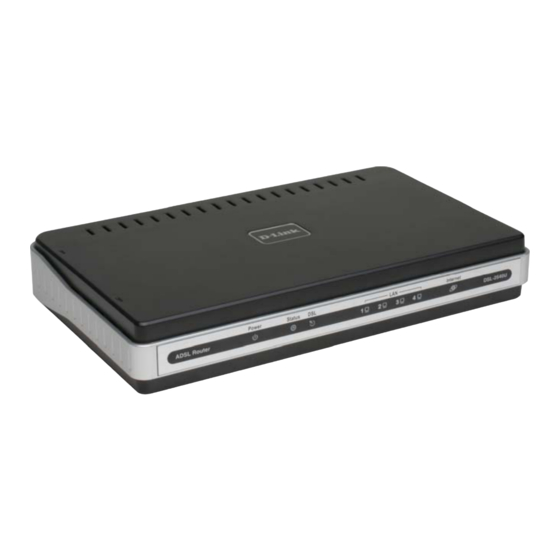
General Information The D-Link DSL-2540U is an ADSL2+ router offering the convenience of 4 ports for additional computers. This user manual provides you with a simple and easy-to- understand format to install and configure your router. Package Contents Included in the package is one of each of the following—... -
Page 5: Front Panel View
Front Panel View Mode Indication Solid The router is powered on. (READY) Green Power No light The power is off. Failure or device malfunction. (NOT READY) Flashing Status Traffic is passing through the device. (INTERNET TRAFFIC) Green Solid DSL is synchronized. Green No Light No carrier signal. -
Page 6: Back Panel View
Back Panel View Port Description On/ Off Press to turn the router on and off. Power Connects to the power adapter. Press for less than 3 seconds to reset the router. Reset Press for 3 seconds or more to revert to factory settings. RJ-45 connects the unit to Ethernet devices such as a PC or a LAN 4-1 switch. -
Page 7: Connecting The Router To Your Computer
Connecting the Router to Your Computer On / Off Reset Power Button Button Port Input Connect the Telephone Cable • Connect one end of the telephone cable to the DSL port on the router and the other end of the cable into the wall socket. Connect the Ethernet Cable •... -
Page 8: Configuring The Router
Configuring the Router To use your web browser to access the web pages used to set up the router, your computer must be configured to “Obtain an IP address automatically”, that is, you must change the IP network settings of your computer so that it is a DHCP client. If you are using Windows XP and do not know how to change your network settings, skip ahead to Appendix A and read the instructions provided. -
Page 9: Home
Home The home section provides configurations for general use, including a Quick Setup Wizard with steps to quickly set up your router for Internet connection. Also included in this section are LAN / WAN setup and DNS configuration. The below sections explains the setup for each. -
Page 11: Connection Type
Connection Type Following is the Connection Type screen where you select the type of network protocol and encapsulation mode over the ATM PVC that your ISP has instructed you to use. The following is a PPPoA example. Click on Next to continue. PPP Username and Password Now, enter the PPP username and password as given by your ISP. -
Page 12: Network Address Translation Settings
Network Address Translation Settings The next step is to configure the Network Address Translation (NAT) settings. For the example, NAT will be enabled. The remaining fields are left as default and then click on Next to continue. -
Page 13: Device Setup
Device Setup You can configure the DSL Router IP address and Subnet Mask for the LAN interface to correspond to your LAN’s IP Subnet. If you want the DHCP server to automatically assign IP addresses, then enable the DHCP server and enter the range of IP addresses that the DHCP server can assign to your computers. -
Page 14: Setup - Summary
Setup - Summary After all of the configurations are done, the WAN Setup Summary screen displays all WAN settings that you have made. Check that the settings are correct before clicking on the Save / Reboot button. Clicking on Save / Reboot will save your settings and restart your router. -
Page 15: Wan
Configure the WAN settings as provided by your ISP. - Page 16 Click on the Add button if you want to add a new connection for the WAN interface and to proceed to the ATM PVC Configuration screen as seen below. The ATM PVC Configuration screen allows you to configure an ATM PVC identifier (VPI and VCI) and select a service category.
- Page 17 The following screen shows the below types of network protocols and encapsulation modes— • PPP over ATM (PPPoA) • PPP over Ethernet (PPPoE) • MAC Encapsulation Routing (MER) • IP over ATM (IpoA) • Bridging If you will be using VLAN tagging, then click on the Enable 802.1q checkbox and then enter the VLAN ID number.
- Page 18 The following screen allows you to enter PPP username and password as well as make any selections regarding your connection. • Dial on demand: Allows you to manually connect to the Internet so you are not permanently connected. Idle timeout timer is included. •...
- Page 19 When finished, click on Next to proceed to the NAT Settings screen. • Enable NAT: Select enable if you wish to share one WAN IP address for multiple computers on your LAN. • Enable Firewall: Select if you wish to enable the router’s firewall for security.
- Page 20 Click Next when finished with your configurations and the below screen will follow displaying the WAN settings that you made. When satisfied with the settings click on the Apply button.
-
Page 21: Lan
After you apply the configurations, it will return to the WAN Setup screen showing the new configurations. Select the Finish button to save the changes and reboot the router. Below is the DSL Router Reboot screen that will appear during the rebooting process. - Page 22 An available option if you will be multicasting is IGMP snooping, for which you can also select standard or blocking mode. If you want the DHCP server to automatically assign IP addresses, enable DHCP server and enter the range of IP addresses that DHCP server can assign. Disable DHCP server if you would like to manually assign IP addresses.
-
Page 23: Dns
DNS Server Configuration Use the DNS Server screen to request automatic assignment of a DNS or to specify a primary and secondary DNS. If you uncheck the Enable Automatic Assigned DNS checkbox, there will appear two additional fields—primary and secondary DNS server—to enter as seen below. Click on Apply to save the configuration. -
Page 24: Dynamic Dns
Dynamic DNS Dynamic DNS is a service for allowing an Internet domain name to be assigned to a varying IP address. This makes it possible for other sites on the Internet to establish connections to you without needing to track the IP address themselves. Click on Add to set up a dynamic DNS configuration. -
Page 25: Logout
Logout To log out of the router’s user interface at any time during the setup, click on the Logout button. A confirmation screen will appear confirming that you really want to log out. Advanced Setup... -
Page 26: Adsl
This section of the setup is an advanced version of the quick setup. If you want to make specific configurations to your router such as creating a virtual server, DMZ, RIP, Quality of Service (QoS), etc., consider going through this advanced setup for a more comprehensive configuration. -
Page 27: Adsl Settings
ADSL Settings The test mode can be selected from the DSL Advanced Settings page. Test modes include—normal, reverb, medley, no retrain, and L3. After you make your selections of the test mode, click on Apply to save these settings first before you go to Tone Selection. -
Page 28: Virtual Server
Virtual Server If you enable NAT (Network Address Translation), you can configure the Virtual Server, Port Triggering, and DMZ Host. NAT—Virtual Servers Setup A virtual server allows you to direct incoming traffic from the WAN side to a specific IP address on the LAN side. The following figure shows the screen that allows you to configure your virtual server(s). - Page 29 Select the virtual server from the drop-down list and complete the server IP address, then click on Apply once.
-
Page 30: Dmz
The following screen appears after you save your selection. To add additional virtual servers, click on the Add button. If you need to remove any of the server names, select the check box and click on the Remove button. You can define the IP address of the DMZ Host on this screen. Enter the IP address and click on Apply. -
Page 31: Snmp
SNMP SNMP—Configuration SNMP is Simple Network Management Protocol that provides a means to monitor status and performance as well as set configuration parameters. It enables a management station to configure, monitor and receive trap messages from network devices. IP Filter IP filters can be configured to manage your incoming and outgoing traffic. -
Page 32: Incoming Ip Filtering Setup
Incoming IP Filtering Setup Incoming IP filter allows specified the WAN traffic to pass through the firewall. Click on the Add button to add incoming filter settings. - Page 33 Enter a filter name, information about the source address (from the WAN side), and information about the destination address (to the LAN side). Select the protocol and WAN interface, then click on Apply to add the setting. The following screen appears when you apply the IP filter. The screen lists the IP filters that were added from the previous screen.
-
Page 34: Outgoing Ip Filtering Setup
Outgoing IP Filtering Setup The outgoing filter will block the LAN traffic from entering the WAN side. Click on the Add button to create filters. - Page 35 The below screen will appear when you click on Add. Input the filter name, source information (from the LAN side), and destination information (from the WAN side). Then click on Apply to save. The following screen appears when you apply the IP filter. The screen lists the IP filters that were added from the previous screen.
-
Page 36: Bridge Filters
Bridge Filters MAC Filtering Setup MAC filtering can forward or block traffic by MAC address. You can change the policy or add settings to the MAC filtering table using the MAC Filtering Setup screen. - Page 37 If you click on Change Policy, a confirmation dialog allows you to verify your change. If you want to add a setting to the MAC filtering table, select protocol type, enter the destination and source MAC address, the necessary frame direction, and WAN interface (bridge mode only).
-
Page 38: Parental Control
After you save the settings, a screen showing the settings will appear. On this screen you will be able to view and delete MAC filtering rules. Parental Control Time of Day Restrictions In a home setting, parents can also restrict the day of the week certain computers can access the router. -
Page 40: Routing
Routing Static route, default gateway, and RIP type routing configurations can be performed here. Routing--Static Route The Static Route page can be used to add a routing table (a maximum of 32 entries can be configured). To proceed, click on Add. -
Page 41: Routing-Default Gateway
Enter the route information and then apply your configurations. Routing—Default Gateway The router has the ability to accept the first received default gateway assignment from one of the PPPoA, PPPoE or MER/DHCP enabled PVC’s. This function is enabled by default as seen below. - Page 42 If you uncheck the Enable Automatic Assigned Default Gateway option, the below screen will be shown. Enter the default gateway IP address or select the established gateway to be used.
-
Page 43: Routing-Rip Configuration
Routing—RIP Configuration If RIP is enabled, the router operation can be configured as active or passive. Quality of Service You can configure the Quality of Service to apply different priorities to traffic on the router. Click on Add to view the Add Network Traffic Class Rule screen. - Page 44 This screen allows you to add a network traffic class rule.
-
Page 45: Port Mapping
Port Mapping Port mapping is a feature that allows you to open ports to allow certain Internet applications on the WAN side to pass through the firewall and enter your LAN. To use this feature, mapping groups should be created. Click on the Add button as displayed below. -
Page 46: Tools
Tools... -
Page 47: Access Control
The tools section contains various administrator functions to maintain your router. Sections include the following—Admin, Time, Remote Log, System, Firmware, and Test. • Admin: Allows you to change the password for the various user names available • Time: Allows you to set the router’s time •... -
Page 48: Access Control-Admin
Access Control—Admin Three user names and passwords—admin, support, and user—can be used to control your router. The passwords for these user names can be changed on the following screen. Enter the user name followed by the old password and the new password that you wish to change to. -
Page 49: Access Control-Services
Access Control—Services Services that can be enabled / disabled on the LAN / WAN are FTP, HTTP, ICMP, SNMP, Telnet, and TFTP. Access Control—IP Address Web access to the router can be limited when Access Control Mode is enabled. The IP addresses of allowed hosts can be added using Access Control IP Address. - Page 50 To assign the IP address of the management station that is permitted to access the local management services, enter the IP address in the box and click on the Apply button.
-
Page 51: Time
Time The Time Settings page allows you to automatically synchronize your time with a time server on the Internet. If you choose to set the router’s time, click on the “automatically synchronize with Internet time servers” checkbox and the below fields appear. -
Page 52: Remote Log
Select from the list of NTP (Network Time Protocol) time servers. Then select the time zone that you are in and click on Apply to save. Remote Log The Log dialog allows you to view and configure the log. To view the log, click on the View System Log button. -
Page 53: System
To configure the system log settings, click on the Configure System Log button to view the following screen. If the log is enabled, the system will log selected events including Emergency, Alert, Critical, Error, Warning, Notice, Informational, and Debugging. All events above or equal to the selected log level will be logged and displayed. -
Page 55: Backup Settings
Backup Settings To save your configurations in a file on your computer so that it may be accessed again later if your current settings are changed, click on the Backup Settings button. The below pop-up screen will appear with a prompt to open or save the file to your computer. -
Page 56: Restore Default Settings
Restore Default Settings Restore Default will delete all current settings and restore the router to factory default settings. Click on the Restore Default Settings button to proceed. The following confirmation dialog will appear confirming your decision to restore default settings. Click on OK to continue. Firmware If your ISP releases new software for this router, follow these steps to perform an upgrade. - Page 57 • Connection to your local network • Connection to your DSL service provider • Connection to your Internet service provider There are three buttons at the bottom of the page—Next Connection (appears only if you have created more than one connection), Test and Test with OAM F4—which will allow you to retest if necessary.
-
Page 58: Status
Status The status section allows you to view general and status information for your router’s connection. Device Info It shows details of the router such as the version of the software, bootloader, LAN IP address, etc. It also displays the current status of your DSL connection as shown below—... -
Page 59: Dhcp Clients
DHCP Clients Access the DHCP Leases screen by clicking “DHCP” under “Statistics”. This shows the computers, identified by the hostname and MAC address that have acquired IP addresses by the DHCP server with the time that the lease for the IP address is up. -
Page 60: Wan Info
WAN Info The WAN Info screen displays WAN connections previously set up in the Home section. The information added in the status section is the extra column for connection status information, displaying either ADSL Link Down or ADSL Link Up. Route Info The Route Info section displays route information showing the IP addresses of the destination, gateway, and subnet mask as well as other route information. -
Page 61: Log
This is the same screen as seen in the Remotelog section under tools. -
Page 62: Lan
The LAN section shows received and transmitted packet information for the Ethernet interfaces. Click on Reset Statistics to renew the information. The WAN section shows received and transmitted packet information for the WAN connections that you have set up. Click on Reset Statistics to renew the information. -
Page 63: Atm
The ATM section displays statistical values for your ATM interface as well as for AAL5 and AAL5 VCC. Click on Reset Statistics to renew the values. -
Page 64: Adsl
ADSL Information contained in the ADSL screen is useful for troubleshooting and diagnostics of connection problems. -
Page 65: Adsl Ber Test
ADSL BER Test A Bit Error Rate Test (BER Test) is a test that reflects the ratio of error bits to the total number transmitted. If you click on the ADSL BER Test button at the bottom of the ADSL Statistics page, the following pop-up screen will appear allowing you to set the tested time and to begin the test. - Page 66 When the test is complete, the following window will display the test results showing the test time, total transferred bits, total error bits and error ratio.