Table of Contents
Advertisement
INVERTER
FR-A701
INSTRUCTION MANUAL (BASIC)
FR-A721-5.5K to 55K
FR-A741-5.5K to 55K
Thank you for choosing this Mitsubishi Inverter.
This Instruction Manual is intended for users who "just want to run the inverter".
If you are going to utilize functions and performance, refer to the FR-A701 Series Instruction Manual (applied) [IB-
0600337ENG]. The Instruction Manual (applied) is separately available from where you purchased the inverter or
your Mitsubishi sales representative.
1
OUTLINE ....................................................................................................... 1
1.1
Product checking and parts identification .........................................................................1
1.2
Inverter and peripheral devices.........................................................................................2
1.3
Method of removal and reinstallation of the front cover....................................................4
1.4
Installation of the inverter and enclosure design ..............................................................6
2
WIRING........................................................................................................ 12
2.1
Terminal connection diagram......................................................................................... 12
2.2
Main circuit terminal specifications................................................................................. 13
2.3
Control circuit specifications........................................................................................... 20
2.4
Connection of motor with encoder (vector control)........................................................ 28
3
PRECAUTIONS FOR USE OF THE INVERTER......................................... 35
3.1
EMC and leakage currents ............................................................................................ 35
3.2
Power-off and magnetic contactor (MC) ........................................................................ 41
3.3
Inverter-driven 400V class motor ................................................................................... 42
3.4
Precautions for use of the inverter ................................................................................. 43
3.5
Failsafe of the system which uses the inverter .............................................................. 45
4
DRIVE THE MOTOR ................................................................................... 47
4.1
Step of operation ............................................................................................................ 47
4.2
Operation panel (FR-DU07)........................................................................................... 48
4.3
Before operation............................................................................................................. 56
4.4
Start/stop from the operation panel (PU operation mode)............................................. 83
4.5
Make a start and stop with terminals (external operation)............................................. 88
4.6
Parameter List ................................................................................................................ 95
5
TROUBLESHOOTING .............................................................................. 139
5.1
Reset method of protective function ............................................................................ 139
5.2
List of fault or alarm display ......................................................................................... 140
5.3
Causes and corrective actions..................................................................................... 141
5.4
Correspondences between digital and actual characters............................................ 156
5.5
Check and clear of the faults history..................................................................... 157
5.6
Check first when you have troubles ............................................................................. 159
6
PRECAUTIONS FOR MAINTENANCE AND INSPECTION ..................... 162
6.1
Inspection item ............................................................................................................. 162
6.2
Measurement of main circuit voltages, currents and powers ...................................... 169
7
SPECIFICATIONS ..................................................................................... 174
7.1
Rating ........................................................................................................................... 174
7.2
Common specifications ................................................................................................ 177
7.3
Outline dimension drawings......................................................................................... 178
7.4
Installation of the heatsink portion outside the enclosure for use................................ 187
CONTENTS
701
1
2
3
4
5
6
7
Advertisement
Table of Contents

Related Manuals for Mitsubishi Electric FR-A701


Summary of Contents for Mitsubishi Electric FR-A701
- Page 1 This Instruction Manual is intended for users who "just want to run the inverter". If you are going to utilize functions and performance, refer to the FR-A701 Series Instruction Manual (applied) [IB- 0600337ENG]. The Instruction Manual (applied) is separately available from where you purchased the inverter or your Mitsubishi sales representative.
- Page 2 This instruction manual (Basic) provides handling information and precautions for use of the equipment. Please forward this instruction manual (Basic) to the end user. This section is specifically about safety matters (3) Test operation and adjustment CAUTION Do not attempt to install, operate, maintain or inspect the inverter until you have read through this instruction manual (Basic) and appended documents •...
-
Page 3: Table Of Contents
— CONTENTS — OUTLINE Product checking and parts identification .............. 1 Inverter and peripheral devices................2 1.2.1 Peripheral devices ........................3 Method of removal and reinstallation of the front cover ......... 4 Installation of the inverter and enclosure design............ 6 1.4.1 Inverter installation environment.................... - Page 4 DRIVE THE MOTOR Step of operation....................47 Operation panel (FR-DU07) ................. 48 4.2.1 Parts of the operation panel (FR-DU07) .................. 48 4.2.2 Basic operation (factory setting) ....................49 4.2.3 Operation lock (Press [MODE] for an extended time (2s)) ............50 4.2.4 Monitoring of output current and output voltage ..............
- Page 5 4.6.2 Parameter list .......................... 98 TROUBLESHOOTING Reset method of protective function ..............139 List of fault or alarm display ................140 Causes and corrective actions ................141 Correspondences between digital and actual characters ........156 Check and clear of the faults history ..............157 Check first when you have troubles ..............
-
Page 6: Specifications
DeviceNet is a registered trademark of ODVA (Open DeviceNet Vender Association, Inc.). Company and product names herein are the trademarks and registered trademarks of their respective owners. REMARKS ⋅ For differences and compatibility between the FR-A701 series and FR-A700 series, refer to page 189. - Page 7 MEMO...
-
Page 8: Outline
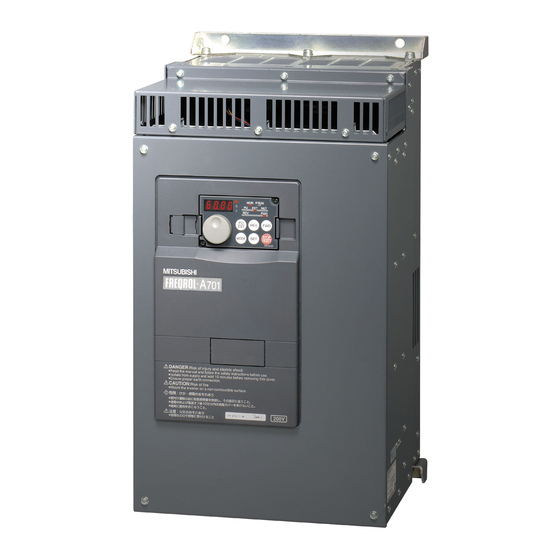
Product checking and parts identification 1 OUTLINE 1.1 Product checking and parts identification Unpack the inverter and check the capacity plate on the front cover and the rating plate on the inverter side face to ensure that the product agrees with your order and the inverter is intact. •... -
Page 9: Inverter And Peripheral Devices
Inverter and peripheral devices 1.2 Inverter and peripheral devices Three-phase AC power supply Use within the permissible power supply Inverter (FR-A701) specifications of the inverter. The life of the inverter is influenced by surrounding air temperature. The surrounding air (Refer to page 174) temperature should be as low as possible within the permissible range. -
Page 10: Peripheral Devices
S-N65 FR-A741-55K 225AF 175A S-N80 Selections for use of the Mitsubishi 4-pole standard motor with power supply voltage of 200VAC/400VAC 50Hz. Select the MCCB according to the inverter power supply capacity. Install one MCCB per inverter. MCCB For installations in the United States or Canada, use the appropriate UL and cUL listed class RK5, class T MCCB type fuse or UL489 molded case circuit breaker (MCCB). -
Page 11: Method Of Removal And Reinstallation Of The
Method of removal and reinstallation of the front cover 1.3 Method of removal and reinstallation of the front cover •Removal of the operation panel 1) Loosen the two screws on the operation panel. 2) Push the left and right hooks of the operation panel (These screws cannot be removed.) and pull the operation panel toward you to remove. - Page 12 Method of removal and reinstallation of the front cover • Reinstallation of the front cover 1) Insert the two fixed hooks on the left side of the 2) Using the fixed hooks as supports, securely press the front cover 2 into the sockets of the inverter. front cover 2 against the inverter.
-
Page 13: Installation Of The Inverter And Enclosure Design
Installation of the inverter and enclosure design 1.4 Installation of the inverter and enclosure design When an inverter enclosure is to be designed and manufactured, heat generated by contained equipment, etc., the environment of an operating place, and others must be fully considered to determine the enclosure structure, size and equipment layout. - Page 14 Installation of the inverter and enclosure design (1) Temperature The permissible surrounding air temperature of the inverter is between -10 and +50 . Always operate the inverter °C °C within this temperature range. Operation outside this range will considerably shorten the service lives of the semiconductors, parts, capacitors and others.
- Page 15 Installation of the inverter and enclosure design (4) Corrosive gas, salt damage If the inverter is exposed to corrosive gas or to salt near a beach, the printed board patterns and parts will corrode or the relays and switches will result in poor contact. In such places, take the measures given in Section (3).
-
Page 16: Cooling System Types For Inverter Enclosure
Installation of the inverter and enclosure design 1.4.2 Cooling system types for inverter enclosure From the enclosure that contains the inverter, the heat of the inverter and other equipment (transformers, lamps, resistors, etc.) and the incoming heat such as direct sunlight must be dissipated to keep the in-enclosure temperature lower than the permissible temperatures of the in-enclosure equipment including the inverter. -
Page 17: Inverter Placement
Installation of the inverter and enclosure design 1.4.3 Inverter placement (1) Installation of the Inverter Installation on the enclosure CAUTION ⋅ When encasing multiple inverters, install them in parallel as a cooling measure. ⋅ Install the inverter vertically. Vertical (2) Clearances around the inverter To ensure ease of heat dissipation and maintenance, leave at least the shown clearances around the inverter. - Page 18 Installation of the inverter and enclosure design (4) Above the inverter Heat is blown up from inside the inverter by the small fan built in the unit. Any equipment placed above the inverter should be heat resistant. (5) Arrangement of multiple inverters When multiple inverters are placed in the same enclosure, generally arrange them horizontally as shown in the figure below (a).
-
Page 19: Wiring
(Common for external power supply transistor) using Pr.291. connector Voltage/current *9 . Because the FR Configurator has not input switch worked with the FR-A701 series, a USB Frequency setting signal (Analog) 10E(+10V) connector can not be used. 10(+5V) Indicator connector Frequency setting (Frequency meter, etc.) -
Page 20: Main Circuit Terminal Specifications
Main circuit terminal specifications 2.2 Main circuit terminal specifications 2.2.1 Specification of main circuit terminal Terminal Terminal Name Description Symbol R/L1, S/L2, AC power input Connect to the commercial power supply. T/L3 U, V, W Inverter output Connect a three-phase squirrel-cage motor. Connected to the AC power supply terminals R/L1 and S/L2. -
Page 21: Terminal Arrangement Of The Main Circuit Terminal, Power Supply And The Motor Wiring
Main circuit terminal specifications 2.2.2 Terminal arrangement of the main circuit terminal, power supply and the motor wiring. 200V class FR-A721-5.5K, 7.5K FR-A721-11K, 15K R1/L11 S1/L21 R1/L11 S1/L21 Screw size Charge lamp (M4) Screw size (M4) Jumper Charge lamp Jumper Screw size (M5) Screw size (11K: M5, 15K: M6) R/L1 S/L2 T/L3... - Page 22 Main circuit terminal specifications 400V class FR-A741-5.5K, 7.5K FR-A741-11K, 15K S1/L21 R1/L11 Screw size (M4) R1/L11 S1/L21 Screw size (M4) Charge lamp Jumper Charge lamp Jumper Screw size (M4) Screw size (M5) N/- P/+ R/L1 S/L2 T/L3 R/L1 S/L2 T/L3 Power supply Motor Power supply...
-
Page 23: Cables And Wiring Length
Main circuit terminal specifications 2.2.3 Cables and wiring length (1) Applied cable size Select the recommended cable size to ensure that a voltage drop will be 2% max. If the wiring distance is long between the inverter and motor, a main circuit cable voltage drop will cause the motor torque to decrease especially at the output of a low frequency. - Page 24 Main circuit terminal specifications The line voltage drop can be calculated by the following formula: 3 × wire resistance[mΩ/m] × wiring distance[m] × current[A] line voltage drop [V]= 1000 Use a larger diameter cable when the wiring distance is long or when it is desired to decrease the voltage drop (torque reduction) in the low speed range.
- Page 25 Main circuit terminal specifications (3) Total wiring length The overall wiring length for connection of a single motor or multiple motors should be within 500m. (The wiring length should be 100m maximum for vector control.) Total wiring length 500m or less 300m 300m 300m + 300m = 600m...
-
Page 26: When Connecting The Control Circuit And The Main Circuit Separately To The Power Supply (Separate Power)
Main circuit terminal specifications 2.2.4 When connecting the control circuit and the main circuit separately to the power supply (separate power) <Connection diagram> When fault occurs, opening of the electromagnetic contactor (MC) on the inverter power supply side results in power loss in the control circuit, disabling the fault output signal retention. -
Page 27: Control Circuit Specifications
Control circuit specifications 2.3 Control circuit specifications 2.3.1 Control circuit terminals indicates that terminal functions can be selected using Pr. 178 to Pr. 196 (I/O terminal function selection) (Refer to chapter 4 of the instruction manual (applied).) (1) Input signals Terminal Terminal Rated... - Page 28 Control circuit specifications Terminal Terminal Rated Refer to Description Symbol Name Specifications page 10VDC When connecting the frequency setting potentiometer at an initial Permissible load status, connect it to terminal 10. Frequency current 10mA Change the input specifications of terminal 2 when connecting it setting power 5VDC to terminal 10E.
- Page 29 Control circuit specifications (2) Output signals Terminal Terminal Rated Refer to Description Symbol Name Specifications page 1 changeover contact output indicates that the inverter Relay output 1 protective function has activated and the output stopped. Contact capacity: (alarm output) Abnormal: No conduction across B-C (Across A-C Continuity), 230VAC 0.3A Normal: Across B-C Continuity (No conduction across A-C) (Power factor=0.4)
-
Page 30: Changing The Control Logic
Control circuit specifications 2.3.2 Changing the control logic The input signals are set to sink logic (SINK) when shipped from the factory. To change the control logic, the jumper connector on the back of the control circuit terminal block must be moved to the other position. - Page 31 Control circuit specifications 4) Sink logic and source logic ⋅ In sink logic, a signal switches on when a current flows from the corresponding signal input terminal. Terminal SD is common to the contact input signals. Terminal SE is common to the open collector output signals. ⋅...
-
Page 32: Control Circuit Terminal Layout
Control circuit specifications 2.3.3 Control circuit terminal layout Terminal screw size: M3.5 Tightening torque: 1.2N·m C2 10E 10 STOP (1) Common terminals of the control circuit (SD, 5, SE) Terminals SD, 5, and SE are all common terminals (0V) for I/O signals and are isolated from each other. Do not earth (ground) these terminals. -
Page 33: Wiring Instructions
Commercially available product examples (as of Feb., 2008) Product Type Maker SGLPEV-T 0.5mm × 4P 1) 10BASE-T cable Mitsubishi Cable Industries, Ltd. 2) RJ-45 connector 5-554720-3 Tyco Electronics Corporation ⋅ The inverter can be connected to the computer and FR-PU04/FR-PU07. -
Page 34: Terminal Block
FA or other computer by a communication cable, a user program can run and Multidrop link monitor the inverter or read and write to parameters. For the Mitsubishi inverter protocol (computer link Inverter Inverter Inverter operation), communication can be performed with the PU connector and RS-485 terminal. -
Page 35: Connection Of Motor With Encoder (Vector Control)
Connection of motor with encoder (vector control) 2.4 Connection of motor with encoder (vector control) Orientation control and encoder feedback control, and speed control, torque control and position control by full-scale vector control operation can be performed using a motor with encoder and a plug-in option FR-A7AP. (1) Structure of the FR-A7AP Mounting Terminal... - Page 36 • Motor used and switch setting Encoder Specification Terminating Resistor Power Motor Selection Switch (SW1) Selection Switch (SW2) Specifications SF-JR Differential Mitsubishi standard motor with encoder Mitsubishi high efficiency motor with SF-HR Differential encoder Others SF-JRCA Differential Mitsubishi constant-torque motor with SF-HRCA...
- Page 37 Length L (m) ⋅ A P clip for earthing (grounding) a Type Length L (m) shielded cable is provided. FR-JCBL5 FR-V7CBL5 FR-JCBL15 FR-V7CBL15 FR-JCBL30 FR-V7CBL30 FR-A701 FR-A701 (FR-A7AP) (FR-A7AP) Encoder Encoder Positioning keyway Positioning keyway MS3106B20-29S MS3106B20-29S (As viewed from wiring side) (As viewed from wiring side) * As the terminal block of the FR-A7AP is an insertion type, earth cables need to be modified.
-
Page 38: Speed Control
Connection of motor with encoder (vector control) (5) Wiring • Speed control Vector control dedicated motor Standard motor with encoder (SF-JR), 5V differential line driver (SF-V5RU, SF-THY), 12V complementary SF-JR motor MCCB SF-V5RU, SF-THY MCCB with encoder Inverter Three-phase R/L1 AC power supply Three-phase S/L2... -
Page 39: Position Control
Connection of motor with encoder (vector control) • Position control Vector control dedicated motor (SF-V5RU, SF-THY), 12V complementary MCCB SF-V5RU, SF-THY Three-phase AC power supply MCCB Positioning unit R/L1 MELSEQ-Q QD75P1 Inverter Three-phase AC S/L2 power supply T/L3 Earth (ground) Thermal External thermal protector... -
Page 40: Initial Setting
Motor capacity poles O/L relay direction encoder pulses SF-JR Motor rated current Motor capacity Number of motor poles 1024 Mitsubishi standard SF-HR Motor rated current Motor capacity Number of motor poles 1024 motor Others Motor rated current Motor capacity Number of motor poles... - Page 41 Connection of motor with encoder (vector control) • Combination with the SF-V5RU Voltage 200V class 400V class Rated speed 1500r/min Base frequency 50Hz Maximum speed 3000r/min Motor frame Motor frame Motor capacity Motor type Inverter type Motor type Inverter type number number 3.7kW...
-
Page 42: Precautions For Use Of The Inverter
Especially for a completely electromagnetic MCCB, one of a slightly large capacity must be selected since its operation characteristic varies with harmonic currents. (Check it in the data of the corresponding breaker.) As an earth leakage circuit breaker, use the Mitsubishi earth leakage circuit breaker designed for harmonics and surge suppression. - Page 43 EMC and leakage currents (3) Selection of rated sensitivity current of earth leakage circuit breaker When using the earth leakage circuit breaker with the inverter circuit, select its rated sensitivity current as follows, independently of the PWM carrier frequency: ⋅ Breaker designed for harmonic and surge suppression Ig1, Ig2: Leakage currents in wire path during commercial Rated sensitivity current: power supply operation...
-
Page 44: Emc Measures
EMC and leakage currents 3.1.2 EMC measures Some electromagnetic noises enter the inverter to malfunction it and others are radiated by the inverter to malfunction peripheral devices. Though the inverter is designed to have high immunity performance, it handles low-level signals, so it requires the following basic techniques. - Page 45 EMC and leakage currents Propagation Path Measures When devices that handle low-level signals and are liable to malfunction due to electromagnetic noises, e.g. instruments, receivers and sensors, are contained in the enclosure that contains the inverter or when their signal cables are run near the inverter, the devices may be malfunctioned by air-propagated electromagnetic noises.
-
Page 46: Power Supply Harmonics
EMC and leakage currents 3.1.3 Power supply harmonics The inverter may generate power supply harmonics from its converter circuit to affect the power generator, power capacitor etc. Power supply harmonics are different from noise and leakage currents in source, frequency band and transmission path. - Page 47 EMC and leakage currents Table 2 Conversion factors for FR-A701 series Class Circuit Type Conversion Factor (Ki) Three-phase bridge With reactor (AC side) K32 = 1.8 (Capacitor smoothing) Table 3 Equivalent Capacity Limits Received Power Voltage Reference Capacity 6.6kV 50kVA...
-
Page 48: Power-Off And Magnetic Contactor (Mc)
Power-off and magnetic contactor (MC) 3.2 Power-off and magnetic contactor (MC) (1) Inverter input side magnetic contactor (MC) On the inverter input side, it is recommended to provide an MC for the following purposes. Refer to page 3 for selection.) 1) To release the inverter from the power supply when the fault occurs or when the drive is not functioning (e.g. -
Page 49: Inverter-Driven 400V Class Motor
Inverter-driven 400V class motor 3.3 Inverter-driven 400V class motor In the PWM type inverter, a surge voltage attributable to wiring constants is generated at the motor terminals. Especially for a 400V class motor, the surge voltage may deteriorate the insulation. When the 400V class motor is driven by the inverter, consider the following measures: Measures It is recommended to take either of the following measures:... -
Page 50: Precautions For Use Of The Inverter
Precautions for use of the inverter 3.4 Precautions for use of the inverter The FR-A701 series is a highly reliable product, but incorrect peripheral circuit making or operation/handling method may shorten the product life or damage the product. Before starting operation, always recheck the following items. - Page 51 Precautions for use of the inverter (13) If the machine must not be restarted when power is restored after a power failure, provide a magnetic contactor in the inverter's input side and also make up a sequence which will not switch on the start signal. If the start signal (start switch) remains on after a power failure, the inverter will automatically restart as soon as the power is restored.
-
Page 52: Failsafe Of The System Which Uses The Inverter
When a fault occurs, the inverter trips to output a fault signal. However, a fault output signal may not be output at an inverter fault occurrence when the detection circuit or output circuit fails, etc. Although Mitsubishi assures best quality products,... -
Page 53: Failsafe Of The System Which Uses The Inverter 45
Failsafe of the system which uses the inverter 4) Checking the motor operating status by the start signal input to the inverter and inverter output current detection signal. The output current detection signal (Y12 signal) is output when the inverter operates and currents flows in the motor. Check if Y12 signal is output when inputting the start signal to the inverter (forward signal is STF signal and reverse signal is STR signal). -
Page 54: Drive The Motor
Step of operation 4 DRIVE THE MOTOR 4.1 Step of operation The inverter needs frequency command and start command. Turning the start command on start the motor rotating and the motor speed is determined by the frequency command (set frequency). Refer to the flow chart below to perform setting. -
Page 55: Operation Panel (Fr-Du07)
Start command forward rotation Start command reverse rotation Setting dial Stop operation (Setting dial: Mitsubishi inverter dial) Used to stop Run command. Used to change the Fault can be reset when protective function is activated frequency setting and (fault). -
Page 56: Basic Operation (Factory Setting)
Operation panel (FR-DU07) 4.2.2 Basic operation (factory setting) Operation mode switchover At powering on (external operation mode) PU Jog operation mode (Refer to page 52) (Example) Value change and frequency flicker. PU operation mode Frequency setting has been (output frequency monitor) written and completed!! Output current monitor Output voltage monitor... -
Page 57: Operation Lock (Press [Mode] For An Extended Time (2S))
Operation panel (FR-DU07) 4.2.3 Operation lock (Press [MODE] for an extended time (2s)) Operation using the setting dial and key of the operation panel can be made invalid to prevent parameter change, and unexpected start or frequency setting. · Set "10 or 11" in Pr. 161, then press for 2s to make the setting dial and key operation invalid. -
Page 58: Monitoring Of Output Current And Output Voltage
Operation panel (FR-DU07) 4.2.4 Monitoring of output current and output voltage POINT Monitor display of output frequency, output current and output voltage can be changed by pushing during monitoring mode. Operation Display Press during operation to choose the output frequency monitor Independently of whether the inverter is running in any operation mode or at a stop, the output current monitor appears by pressing... -
Page 59: Change The Parameter Setting Value
Operation panel (FR-DU07) 4.2.7 Change the parameter setting value Changing example Change the Pr. 1 Maximum frequency . Operation Display Screen at powering on The monitor display appears. PU indication is lit. Press to choose the PU operation mode. The parameter Press to choose the parameter number read... -
Page 60: Parameter Clear, All Parameter Clear
Operation panel (FR-DU07) 4.2.8 Parameter clear, all parameter clear POINT · Set "1" in Pr. CL parameter clear , ALLC all parameter clear to initialize all parameters. (Parameters are not cleared when "1" is set in Pr. 77 Parameter write selection.) ·... -
Page 61: Parameter Copy And Parameter Verification
Verify parameters in the inverter and operation panel. (Refer to page 55.) REMARKS · When the copy destination inverter is not the FR-A701 series or parameter copy write is performed after parameter copy read is stopped, "model error ( )" is displayed. -
Page 62: Operation Display
" and " " flicker to complete verification. Flicker ··· Parameter verification complete!! REMARKS When the copy destination inverter is not the FR-A701 series, "model error ( )" is displayed. flickers ... Why? Set frequencies, etc. may be different. Check set frequencies. -
Page 63: Before Operation
Before operation 4.3 Before operation 4.3.1 Simple mode parameter list For simple variable-speed operation of the inverter, the initial setting of the parameters may be used as they are. Set the necessary parameters to meet the load and operational specifications. Parameter setting, change and check can be made from the operation panel (FR-DU07). -
Page 64: Overheat Protection Of The Motor By The Inverter (Pr. 9)
Before operation 4.3.2 Overheat protection of the motor by the inverter (Pr. 9) Set the rated motor current in Pr. 9 Electronic thermal O/L relay to protect the motor from overheat. Parameter Name Initial Value Setting Range Description Number Inverter rated Electronic thermal O/L relay 0 to 500A Set the rated motor current. -
Page 65: When The Rated Motor Frequency Is 50Hz (Pr. 3)
Before operation 4.3.3 When the rated motor frequency is 50Hz (Pr. 3) First, check the motor rating plate. If a frequency given on the rating plate is "50Hz" only, always set Pr. 3 Base frequency to "50Hz". Leaving the base frequency unchanged from "60Hz" may make the voltage low and the torque insufficient. It may result in an inverter trip (E.OC ) due to overload. -
Page 66: Increase The Starting Torque (Pr. 0)
Before operation 4.3.4 Increase the starting torque (Pr. 0) Set this parameter when "the motor with a load will not rotate", "an alarm [OL] is output, resulting in an inverter trip due to [OC1], etc. Parameter Setting Name Initial Value Description Number Range... -
Page 67: Limit The Maximum And Minimum Output Frequency (Pr. 1, Pr. 2)
Before operation 4.3.5 Limit the maximum and minimum output frequency (Pr. 1, Pr. 2) Motor speed can be limitted. Parameter Name Initial Value Setting Range Description Number Maximum frequency 120Hz 0 to 120Hz Set the upper limit of the output frequency. Minimum frequency 0 to 120Hz Set the lower limit of the output frequency. -
Page 68: Change Acceleration And Deceleration Time (Pr. 7, Pr. 8)
Before operation 4.3.6 Change acceleration and deceleration time (Pr. 7, Pr. 8) Set in Pr. 7 Acceleration time a larger value for a slower speed increase and a smaller value for a faster speed increase. Set in Pr. 8 Deceleration time a larger value for a slower speed decrease and a smaller value for a faster speed decrease. Parameter Name Initial Value... -
Page 69: Selection Of The Start Command And Frequency Command Locations (Pr. 79)
Before operation 4.3.7 Selection of the start command and frequency command locations (Pr. 79) Select the start command location and frequency command location. LED Indication Parameter Initial Setting Name Description : Off Number Value Range : On External operation mode Use external/PU switchover mode (press to switch between the PU and external operation mode. -
Page 70: Large Starting Torque And Low Speed Torque Are Necessary (Advanced Magnetic Flux Vector Control, Real Sensorless Vector Control) (Pr. 71, Pr. 80, Pr. 81, Pr. 800)
· The motor capacity should be equal to or one rank lower than the inverter capacity. · Motor to be used is either Mitsubishi standard motor, high efficiency motor (SF-JR, SF-HR two-pole, four-pole, six-pole 3.7kW or more) or Mitsubishi constant torque motor (SF-JRCA four-pole, SF-HRCA 3.7kW or more). When using a motor other than the above (other manufacturer's motor), perform offline auto tuning without fail. -
Page 71: Test Run
<Selection method of advanced magnetic flux vector control> Perform secure wiring. (Refer to page 12.) Set the motor. (Pr. 71) (Refer to page 63.) Motor Pr. 71 Setting Remarks SF-JR 0 (initial value) Mitsubishi standard motor SF-HR Mitsubishi high Offline auto tuning is Others efficiency motor necessary. - Page 72 Before operation <Selection method of real sensorless vector control (speed control) > Speed control is exercised to match the speed command and actual motor speed. Perform secure wiring. (Refer to page 12.) Set the motor. (Pr. 71) (Refer to page 64.) Set "3"...
-
Page 73: Higher Accuracy Operation Using A Motor With Encoder (Vector Control) (Pr.71, Pr.80, Pr.81, Pr.359, Pr.369, Pr.800)
Before operation 4.3.9 Higher accuracy operation using a motor with encoder (Vector control) (Pr.71, Pr.80, Pr.81, Pr.359, Pr.369, Pr.800) Vector Vector Vector Full-scale vector control can be performed fitting the FR-A7AP and using a motor with encoder. Fast response/ high accuracy speed control (zero speed control, servo lock), torque control, and position control can be performed. - Page 74 · The motor capacity should be equal to or one rank lower than the inverter capacity. Motor to be used is either Mitsubishi standard motor with encoder, high efficiency motor (SF-JR, SF-HR two-pole, · four-pole, six-pole 3.7kW or more) or Mitsubishi constant torque motor (SF-JRCA four-pole, SF-HRCA 3.7kW or more) or vector control dedicated motor (SF-V5RU).
- Page 75 Before operation <Selection method of speed control> Speed control is exercised to match the speed command and actual motor speed. Perform secure wiring. (Refer to page 31.) Mount the FR-A7AP. Set the motor and encoder. (Pr. 71, Pr. 359, Pr. 369) Set Pr.
- Page 76 Before operation <Selection method of torque control> Torque control is exercised to develop torque as set in the torque command. The motor speed becomes constant when the motor output torque and load torque are balanced. For torque control, therefore, the speed is determined by the load. For torque control, the motor gains speed as the motor output torque becomes greater than the motor load.
- Page 77 Before operation <Selection method of position control> In the position control, the speed command is calculated so that the difference between command pulse (or parameter setting) and the number of feedback pulses from the encoder is zero to run the motor. This inverter can perform conditional position feed by contact input and position control by inverter conditional pulse input.
-
Page 78: To Exhibit The Best Performance Of The Motor Performance (Offline Auto Tuning)
· · Even when motors (other manufacturer's motor, SF-JRC, etc.) other than Mitsubishi standard motor, high efficiency motor (SF-JR SF-HR 3.7kW or more), Mitsubishi constant-torque motor (SF-JRCA four-pole, SF-HRCA 3.7kW or more) and vector control dedicated motor (SF-V5RU (1500r/min series)) are used or the wiring length is long, using the offline auto tuning function runs the motor with the optimum operating characteristics. - Page 79 Before operation (1) Before performing offline auto tuning Check the following before performing offline auto tuning. Make sure advanced magnetic flux vector control (Pr. 80, Pr. 81), real sensorless vector control or vector control (Pr. · 800) is selected. (Refer to page 63 ) A motor should be connected.
- Page 80 Pr. 83 and Pr. 84) 5) Set Pr. 71 Applied motor according to the motor used. Motor Pr. 71 Setting SF-JR Mitsubishi standard motor SF-HR Mitsubishi high efficiency motor Others SF-JRCA 4P Mitsubishi constant-torque motor SF-HRCA Others (SF-JRC, etc.) SF-V5RU (1500r/min series)
- Page 81 Before operation (3) Execution of tuning CAUTION · Before performing tuning, check the monitor display of the operation panel (FR-DU07) or parameter unit (FR-PU04/FR- PU07) if the inverter is in the state ready for tuning. (Refer to 2) below) When the start command is turned on under V/F control, the motor starts.
- Page 82 Before operation 3)When offline auto tuning ends, press of the operation panel during PU operation. For external operation, turn off the start signal (STF signal or STR signal). This operation resets the offline auto tuning and the PU's monitor display returns to the normal indication. (Without this operation, next operation cannot be started.) REMARKS ·...
-
Page 83: Operation Method
Before operation 4.3.11 High accuracy operation unaffected by the motor temperature (online auto tuning) (Pr. 95) Magnetic flux Magnetic flux Magnetic flux Sensorless Sensorless Sensorless Vector Vector Vector When online auto tuning is selected under advanced magnetic flux vector control, real sensorless vector control or vector control, excellent torque accuracy is provided by temperature compensation even if the secondary resistance value of the motor varies with the rise of the motor temperature. -
Page 84: To Perform High Accuracy/Fast Response Operation (Gain Adjustment Of Real Sensorless Vector Control And Vector Control) (Pr. 818 To Pr. 821, Pr. 880)
Before operation 4.3.12 To perform high accuracy/fast response operation (gain adjustment of real sensorless vector control and vector control) (Pr. 818 to Pr. 821, Pr. 880) Sensorless Sensorless Sensorless Vector Vector Vector The ratio of the load inertia to the motor inertia (load moment of inertia) is estimated in real time from the torque command and speed during motor operation by vector control. - Page 85 Before operation 2) Each control gain is automatically set from the load inertia ratio estimated during acceleration/deceleration operation and the Pr. 818 Easy gain tuning response level setting value. Pr. 880 Load inertia ratio is used as the initial value of the load inertia ratio for tuning. Estimated value is set in Pr. 880 during tuning.
- Page 86 Before operation (4) Manual input speed control gain adjustment · Make adjustment when any of such phenomena as unusual machine vibration/noise, low response level and overshoot has occurred. Proportional gain · Pr. 820 Speed control P gain 1 = "60%" (initial value) is equivalent to 120rad/s (speed responce of the motor alone).
- Page 87 Before operation (5) When using a multi-pole motor (8 poles or more) Specially when using a multi-pole motor with more than 8 poles under real sensorless vector control or vector control, adjust Pr. 820 Speed control P gain 1 and Pr. 824 Torque control P gain 1 according to the motor referring to the following methods.
- Page 88 Before operation (6) Troubleshooting (speed) Phenomenon Cause Countermeasures (1) The motor wiring is wrong (1) Wiring check Select V/F control (set "9999" in Pr. 80 or Pr. 81 ) and check the rotation direction of the motor. For the SF-V5RU (1500r/min series), set "160V (320V)"...
- Page 89 Before operation Phenomenon Cause Countermeasures (1) The speed command varies. (1) -1 Check that a correct speed command comes from the command device. (Take measures against noises.) (1) -2 Decrease Pr. 72 PWM frequency selection. (1) -3 Increase Pr. 822 Speed setting filter 1. (Refer to chapter 4 of the instruction manual (applied) ) Motor speed is unstable.
-
Page 90: Start/Stop From The Operation Panel (Pu Operation Mode)
Start/stop from the operation panel (PU operation mode) 4.4 Start/stop from the operation panel (PU operation mode) [Connection diagram] POINT Inverter Three-phase R/L1 From where is the frequency command given? S/L2 Motor AC power supply · Operation at the frequency set in the frequency setting T/L3 mode of the operation panel →Refer to 4.4.1 (Refer to page 83) -
Page 91: Use The Setting Dial Like A Potentiometer To Perform Operation
Start/stop from the operation panel (PU operation mode) 4.4.2 Use the setting dial like a potentiometer to perform operation. POINT Set "1" (setting dial potentiometer mode) in Pr. 161 Frequency setting/key lock operation selection. Operation example Change the frequency from 0Hz to 60Hz during operation Operation Display Screen at powering on... -
Page 92: Use Switches To Give A Start Command And A Frequency Command (Multi-Speed Setting)
Start/stop from the operation panel (PU operation mode) 4.4.3 Use switches to give a start command and a frequency command (multi-speed setting) POINT · Use to give a start command. · Pr. 79 Operation mode selection must be set to "4" (external/PU combined operation mode 2) ·... -
Page 93: Perform Frequency Setting By Analog (Voltage Input)
Start/stop from the operation panel (PU operation mode) 4.4.4 Perform frequency setting by analog (voltage input) POINT · Use to give a start command. · Pr. 79 Operation mode selection must be set to "4" (external/PU combined operation mode 2) [Connection diagram] (The inverter supplies 5V of power to the frequency setting potentiometer.(Terminal 10)) Inverter... -
Page 94: Perform Frequency Setting By Analog (Current Input)
Start/stop from the operation panel (PU operation mode) 4.4.5 Perform frequency setting by analog (current input) POINT · Use to give a start command. · Turn the AU signal on. · Pr. 79 Operation mode selection must be set to "4" (external/PU combined operation mode 2) [Connection diagram] Inverter Three-phase... -
Page 95: Make A Start And Stop With Terminals (External Operation)
Make a start and stop with terminals (external operation) 4.5 Make a start and stop with terminals (external operation) POINT From where is the frequency command given? · Operation at the frequency set in the frequency setting mode of the operation panel → Refer to 4.5.1(Refer to page 88) ·... -
Page 96: Use Switches To Give A Start Command And A Frequency Command (Multi-Speed Setting) (Pr. 4 To Pr. 6)
Make a start and stop with terminals (external operation) 4.5.2 Use switches to give a start command and a frequency command (multi-speed setting) (Pr. 4 to Pr. 6) POINT · Start command by terminal STF (STR)-SD · Frequency command by terminal RH, RM, RL and STR-SD ·... -
Page 97: External Operation
Make a start and stop with terminals (external operation) [EXT] is not lit even when is pressed ... Why? Switchover of the operation mode with is valid when Pr. 79 = "0" (initial value). 50Hz, 30Hz and 10Hz are not output from RH, RM and RL respectively when they are turned on..Why? Check for the setting of Pr. -
Page 98: Perform Frequency Setting By Analog (Voltage Input)
Make a start and stop with terminals (external operation) 4.5.3 Perform frequency setting by analog (voltage input) [Connection diagram] (The inverter supplies 5V of power to frequency setting potentiometer. (Terminal 10)) Inverter Three-phase R/L1 Motor S/L2 AC power supply T/L3 Forward rotation start Reverse rotation... -
Page 99: Change The Frequency (60Hz) Of The Maximum Value Of Potentiometer (At 5V, Initial Value)
Make a start and stop with terminals (external operation) The motor will not rotate ... Why? Check that [EXT] is lit. [EXT] is valid when Pr. 79 = "0" (initial value) or "2". to lit [EXT]. Check that wiring is correct. Check once again. Change the frequency (0Hz) at the minimum voltage input (at 0V, initial value) Adjust the frequency in calibration parameter C2 Terminal 2 frequency setting bias frequency. -
Page 100: Perform Frequency Setting By Analog (Current Input)
Make a start and stop with terminals (external operation) 4.5.5 Perform frequency setting by analog (current input) POINT · Switch terminal STF(STR)-SD on to give a start command. · Turn the AU signal on. · Set "2" (external operation mode) in Pr. 79 Operation mode selection [Connection diagram] Inverter Three-phase... -
Page 101: Change The Frequency (60Hz) Of The Maximum Value Of Potentiometer (At 20Ma, Initial Value)
Make a start and stop with terminals (external operation) The motor will not rotate ... Why? Check that [EXT] is lit. [EXT] is valid when Pr. 79 = "0" (initial value) or "2". to lit [EXT]. Check that the AU signal is on. Turn the AU signal on. -
Page 102: Parameter List
Parameter List 4.6 Parameter List 4.6.1 List of parameters classified by purpose of use This instruction manual provides basic explanation of parameters. For parameters not stated, refer to the "chapter 4 Parameter" of the instruction manual (applied). Set the parameters according to the operating conditions. The following list indicates purpose of use and corresponding parameters. - Page 103 Parameter List Purpose of Use Parameter Number Pr. 7, Pr. 8, Pr. 20, Pr. 21, Pr. 44, Acceleration/deceleration time setting Pr. 45, Pr. 110, Pr. 111 Starting frequency Pr. 13, Pr. 571 Pr. 29, Pr. 140 to Pr. 143, Pr.380 to Acceleration/deceleration Acceleration/deceleration pattern and backlash measures Pr.
- Page 104 Parameter List Purpose of Use Parameter Number Energy saving control selection Pr. 60 Energy saving operation How much energy can be saved (energy saving monitor) Pr. 891 to Pr. 899 Carrier frequency and SoftPWM selection Pr. 72, Pr. 240 Reduction of the motor noise Measures against noise and Pr.
-
Page 105: Parameter List
Parameter List 4.6.2 Parameter list · indicates simple mode parameters. · The abbreviations in the explanations below indicate: ...V/F control ...advanced magnetic flux vector control Magnetic flux Magnetic flux Magnetic flux ...real sensorless vector control Sensorless Sensorless Sensorless ...vector control. Vector Vector Vector... - Page 106 Parameter List Parameter Para Param param meter eter eter Incre Initial copy clear Name Range Description clear ments Value : enabled × : disabled Set the motor acceleration time. 0.1/ 0 to 3600/ * The initial value differs according to the Acceleration time 5/15s 0.01s...
- Page 107 Parameter List Parameter Para Param param meter eter eter Incre Initial copy clear Name Range Description clear ments Value : enabled × : disabled For constant torque load For variable-torque load Boost for reverse rotation 0% For constant torque lift Boost for forword rotation 0% RT signal ON ..For constant-torque load...
- Page 108 Parameter List Parameter Para Param param meter eter eter Incre Initial copy clear Name Range Description clear ments Value : enabled × : disabled Stall prevention operation selection becomes invalid. Function as stall prevention operation Stall prevention under V/F control and advanced magnetic 0.1% 150% operation level...
- Page 109 Parameter List Parameter Para Param param meter eter eter Incre Initial copy clear Name Range Description clear ments Value : enabled × : disabled This functions as torque limit level under real sensorless vector control. Torque limit level 0.1% 150% 0 to 400% Refer to page 101 for stall prevention operation level.
- Page 110 Parameter List Parameter Para Param param meter eter eter Incre Initial copy clear Name Range Description clear ments Value : enabled × : disabled Linear acceleration/ deceleration S-pattern acceleration/deceleration A Acceleration/ S-pattern acceleration/deceleration B deceleration pattern Backlash measures selection S-pattern acceleration/deceleration C S-pattern acceleration/deceleration D Backlash acceleration 0.01Hz...
- Page 111 Parameter List Parameter Para Param param meter eter eter Incre Initial copy clear Name Range Description clear ments Value : enabled × : disabled Up-to-frequency 0.1% 0 to 100% Set the level where the SU signal turns on. sensitivity Output frequency Set the frequency where the FU (FB) 0.01Hz 0 to 400Hz...
- Page 112 Parameter List Parameter Para Param param meter eter eter Incre Initial copy clear Name Range Description clear ments Value : enabled × : disabled 0, 5 to 8, Select monitor to be displayed on the operation panel and parameter unit and 10 to 14, monitor to be output to the terminal FM and DU/PU main display...
- Page 113 Parameter List Parameter Para Param param meter eter eter Incre Initial copy clear Name Range Description clear ments Value : enabled × : disabled Set the full-scale value to output the output Frequency 0.01Hz 60Hz 0 to 400Hz frequency monitor value to terminal FM monitoring reference and AM.
- Page 114 Parameter List Parameter Para Param param meter eter eter Incre Initial copy clear Name Range Description clear ments Value : enabled × : disabled Setting value (rated motor current) is 0 to 500A Reference current referenced 0.01A 9999 9999 Rated inverter current is referenced Setting value is a limit Shortest acceleration/ value...
- Page 115 Value : enabled × : disabled Thermal characteristics of a standard motor Thermal characteristics of the Mitsubishi constant-torque motor Thermal characteristic of standard motor Adjustable 5 points V/F Thermal characteristics of the Mitsubishi vector motor SF-V5RU (1500r/min series)
- Page 116 Parameter List Parameter Para Param param meter eter eter Incre Initial copy clear Name Range Description clear ments Value : enabled × : disabled PWM carrier frequency can be changed. The setting displayed is in [kHz]. Note that 0 indicates 0.7kHz, 15 indicates 14.5kHz.
- Page 117 Parameter List Parameter Para Param param meter eter eter Incre Initial copy clear Name Range Description clear ments Value : enabled × : disabled Without fault code output With fault code output Fault code output selection Fault code output at fault occurrence only Write is enabled only during a stop Parameter write is disabled.
- Page 118 Parameter List Parameter Para Param param meter eter eter Incre Initial copy clear Name Range Description clear ments Value : enabled × : disabled 0.4 to 55kW Set the applied motor capacity. Motor capacity 0.01kW 9999 9999 V/F control is performed 2, 4, 6, 8, 10 Set the number of motor poles.
- Page 119 (The value measured by offline auto tuning Motor excitation is automatically set.) × 0.01A 9999 current Use the Mitsubishi motor (SF-JR, SF-HR, 9999 SF-JRCA, SF-HRCA, SF-V5RU (1500r/ min series)) constants Set the rated motor voltage(V). Rated motor 200/ * The initial values differ according to the 0.1V...
- Page 120 Second motor is automatically set.) × 0.001Ω 9999 constant (R1) Use the Mitsubishi motor (SF-JR, SF-HR, 9999 SF-JRCA, SF-HRCA, SF-V5RU (1500r/ min series)) constants Tuning data of the second motor 0 to 50Ω (The value measured by offline auto tuning Second motor is automatically set.)
- Page 121 Parameter List Parameter Para Param param meter eter eter Incre Initial copy clear Name Range Description clear ments Value : enabled × : disabled 0 to 400Hz, V/F1(first frequency) 0.01Hz 9999 9999 V/F1(first frequency 0.1V 0 to 1000V voltage) V/F2(second 0 to 400Hz, 0.01Hz 9999...
- Page 122 Parameter List Parameter Para Param param meter eter eter Incre Initial copy clear Name Range Description clear ments Value : enabled × : disabled Specify the inverter station number. PU communication Set the inverter station numbers when two 0 to 31 station number or more inverters are connected to one personal computer.
- Page 123 Parameter List Parameter Para Param param meter eter eter Incre Initial copy clear Name Range Description clear ments Value : enabled × : disabled PID control Set the frequency at which the control is 0 to 400Hz automatically changed to PID control. automatic 0.01Hz 9999...
- Page 124 Parameter List Parameter Para Param param meter eter eter Incre Initial copy clear Name Range Description clear ments Value : enabled × : disabled Electronic bypass Without electronic bypass sequence sequence selection With electronic bypass sequence MC switchover Set the operation interlock time of MC2 0.1s 0 to 100s interlock time...
- Page 125 Parameter List Parameter Para Param param meter eter eter Incre Initial copy clear Name Range Description clear ments Value : enabled × : disabled Output current Set the output current detection level. 0.1% 150% 0 to 220% detection level 100% is the rated inverter current. Set the output current detection period.
- Page 126 Parameter List Parameter Para Param param meter eter eter Incre Initial copy clear Name Range Description clear ments Value : enabled × : disabled 0 to 9, 0: Low-speed operation command 12 to 20, 1: Middle-speed operation command STF terminal 22 to 28, 2: High-speed operation command ×...
- Page 127 Parameter List Parameter Para Param param meter eter eter Incre Initial copy clear Name Range Description clear ments Value : enabled × : disabled 0, 100: Inverter running 0 to 6, 8, 1, 101: Up to frequency RUN terminal 10 to 20, ×...
- Page 128 Parameter List Parameter Para Param param meter eter eter Incre Initial copy clear Name Range Description clear ments Value : enabled × : disabled Operates at power on Cooling fan on/off control invalid (The cooling fan is always on at power on) Cooling fan Cooling fan on/off control valid operation selection...
- Page 129 Parameter List Parameter Para Param param meter eter eter Incre Initial copy clear Name Range Description clear ments Value : enabled × : disabled Displays whether the control circuit capacitor, main circuit capacitor, cooling Life alarm status × × × (0 to 15) fan, and each parts of the inrush current display...
- Page 130 Parameter List Parameter Para Param param meter eter eter Incre Initial copy clear Name Range Description clear ments Value : enabled × : disabled Without stop-on contact control and load Stop-on contact/ torque high-speed frequency control load torque high- Stop-on contact control speed frequency Load torque high speed frequency control control selection...
- Page 131 Parameter List Parameter Para Param param meter eter eter Incre Initial copy clear Name Range Description clear ments Value : enabled × : disabled Set to the rated slip frequency of the motor Brake opening + about 1.0Hz. 0.01Hz 0 to 30Hz This parameter may be only set if Pr.
- Page 132 Parameter List Parameter Para Param param meter eter eter Incre Initial copy clear Name Range Description clear ments Value : enabled × : disabled Droop control is invalid Set the drooping amount at the rated Droop gain 0.1% 0.1 to torque as a percentage with respect to the 100% rated frequency.
- Page 133 Set the communication check time interval. 0.1 to 999.8s (same specifications as Pr. 122) check time interval No communication check (signal loss 9999 detection) Mitsubishi inverter After setting change, (computer link) reset (switch power protocol off, then on) the Protocol selection inverter.
- Page 134 Parameter List Parameter Para Param param meter eter eter Incre Initial copy clear Name Range Description clear ments Value : enabled × : disabled Internal stop position command (Pr.356) Stop position External stop position command (FR-A7AX 9999 command selection 16-bit data) 9999 Orientation control invalid Decrease the motor speed to the set value...
- Page 135 Parameter List Parameter Para Param param meter eter eter Incre Initial copy clear Name Range Description clear ments Value : enabled × : disabled The orientation complete signal (ORA) is output delaying the set time after in- Completion signal 0.1s 0.5s 0 to 5s position zone is entered.
- Page 136 Parameter List Parameter Para Param param meter eter eter Incre Initial copy clear Name Range Description clear ments Value : enabled × : disabled Signal loss detection is invalid Encoder signal loss detection enable/ disable selection Signal loss detection is valid When the cable of the encoder signal is broken during encoder feedback control, orientation control, or vector control, signal...
- Page 137 Parameter List Parameter Para Param param meter eter eter Incre Initial copy clear Name Range Description clear ments Value : enabled × : disabled Position Feed Selection Method Speed First position feed 0 to 9999 amount lower 4 digits High speed First position feed (Pr.4) 0 to 9999...
- Page 138 Parameter List Parameter Para Param param meter eter eter Incre Initial copy clear Name Range Description clear ments Value : enabled × : disabled Remote output data No remote output clear at powering off data held at Remote output data resetting Remote output held at powering off...
- Page 139 Parameter List Parameter Para Param param meter eter eter Incre Initial copy clear Name Range Description clear ments Value : enabled × : disabled Use the speed command value during speed control as speed limit. According to Pr. 808 and Pr. 809, set the speed limit in forward and reverse rotation directions individually.
- Page 140 Parameter List Parameter Para Param param meter eter eter Incre Initial copy clear Name Range Description clear ments Value : enabled × : disabled Set the proportional gain for the current control of the q and d axes. (Increasing the Torque control P 100% 0 to 200%...
- Page 141 Parameter List Parameter Para Param param meter eter eter Incre Initial copy clear Name Range Description clear ments Value : enabled × : disabled Set the contact signal (X42, X43) based- torque bias amount using Pr.841 to Pr.843. Set the terminal 1-based torque bias amount as desired in C16 to C19.
- Page 142 Parameter List Parameter Para Param param meter eter eter Incre Initial copy clear Name Range Description clear ments Value : enabled × : disabled You can make setting to output a signal if Torque detection 0.1% 150% 0 to 400% the motor torque exceeds the predetermined value.
- Page 143 Parameter List Parameter Para Param param meter eter eter Incre Initial copy clear Name Range Description clear ments Value : enabled × : disabled Regeneration avoidance function invalid Regeneration Regeneration avoidance function is always avoidance valid operation selection Regeneration avoidance function is valid only at constant speed Set the bus voltage level at which regeneration avoidance operates.
- Page 144 Parameter List Parameter Para Param param meter eter eter Incre Initial copy clear Name Range Description clear ments Value : enabled × : disabled Set the load factor for commercial power- supply operation. Load factor 0.1% 100% 30 to 150% This value is used to calculate the power consumption estimated value during commercial power supply operation.
- Page 145 Parameter List Parameter Para Param param meter eter eter Incre Initial copy clear Name Range Description clear ments Value : enabled × : disabled Terminal 1 bias Set the frequency on the bias side of × 0.01Hz 0 to 400Hz (917) frequency (speed) terminal 1 input.
-
Page 146: Troubleshooting
Reset method of protective function 5 TROUBLESHOOTING When a fault occurs in the inverter, the inverter trips and the PU display automatically changes to any of the following fault or alarm indications. If the fault does not correspond to any of the following faults or if you have any other problem, please contact your sales representative. -
Page 147: List Of Fault Or Alarm Display
List of fault or alarm display 5.2 List of fault or alarm display Operation Panel Refer Operation Panel Refer Name Name Indication Indication E.PTC* PTC thermistor operation E - - - Faults history E.OPT Option alarm HOLD Operation panel lock E.OP3 Communication option alarm Er1 to 4 Parameter write error E. -
Page 148: Causes And Corrective Actions
Causes and corrective actions 5.3 Causes and corrective actions (1) Error message A message regarding operational troubles is displayed. Output is not shut off. Operation Panel HOLD Indication Name Operation panel lock Description Operation lock mode is set. Operation other than is made invalid. - Page 149 2. Check that the power is not turned off or an operation panel is not disconnected, etc. during parameter copy read. 1. Use the same model (FR-A701 series) for parameter copy and verification. Corrective action 2. Perform parameter copy read again.
- Page 150 Causes and corrective actions (2) Warnings When the protective circuit is activated, the output is not shut off. Operation Panel FR-PU04 Indication FR-PU07 Name Stall prevention (overcurrent) When the output current (output torque during real sensorless vector control or vector control) of the inverter exceeds the stall prevention operation level (Pr.
- Page 151 Displayed when parameters are copied between the FR-A701 series and FR-A700 series 75K or more. Check point Check that parameters are not copied between the FR-A701 series and FR-A700 series 75K or more. Corrective action Copy between the same FR-A701 series.
- Page 152 Causes and corrective actions (3) Alarm When an alarm occurs, the output is not shut off. You can also output an alarm signal by making parameter setting. (Set "98" in any of Pr. 190 to Pr. 196 (output terminal function selection). (Refer to chapter 4 of the instruction manual (applied).)) Operation Panel...
- Page 153 Causes and corrective actions Operation Panel FR-PU04 E.OC3 OC During Dec Indication FR-PU07 Name Overcurrent trip during deceleration or stop When the inverter output current reaches or exceeds approximately 220% of the rated inverter current during Description deceleration (other than acceleration or constant speed), the protective circuit is activated to stop the inverter output.
- Page 154 Causes and corrective actions Operation Panel FR-PU04 E.OV3 OV During Dec Indication FR-PU07 Name Regenerative overvoltage trip during deceleration or stop If regenerative energy causes the inverter's internal main circuit DC voltage to reach or exceed the specified value, the protective circuit is activated to stop the inverter output. The circuit may also be Description activated by a surge voltage produced in the power supply system.
- Page 155 Causes and corrective actions Operation Panel FR-PU04 E.FIN H/Sink O/Temp Indication FR-PU07 Name Fin overheat If the heatsink overheats, the temperature sensor is actuated to stop the inverter output. The FIN signal can be output when the temperature becomes approximately 85% of the heatsink overheat protection operation temperature.
- Page 156 Causes and corrective actions FR-PU04 Operation Panel Stll Prev STP ( OL shown during stall E.OLT Indication prevention operation) FR-PU07 Name Stall prevention If the frequency has fallen to 0.5Hz by stall prevention operation and remains for 3s, a fault (E.OLT) appears and trips the inverter.
- Page 157 Causes and corrective actions Operation Panel FR-PU04 E.OPT Option Fault Indication FR-PU07 Name Option alarm Appears when torque command by the plug-in option is selected using Pr. 804 Torque command source Description selection and no plug-in option is mounted. Appears when the switch for the manufacturer setting of the plug-in option is changed. Check point ·...
- Page 158 Causes and corrective actions Operation Panel FR-PU04 E.PUE PU Leave Out Indication FR-PU07 Name PU disconnection · This function stops the inverter output if communication between the inverter and PU is suspended, e.g. the operation panel and parameter unit is disconnected, when "2", "3", "16" or "17" was set in Pr. 75 Reset selection/disconnected PU detection/PU stop selection.
- Page 159 Causes and corrective actions Operation Panel FR-PU04 E.OS E. OS Indication FR-PU07 Name Overspeed occurence Stops the inverter output when the motor speed exceeds the Pr. 374 Overspeed detection level during Description encoder feedback control real sensorless vector control and vector control. This protective function does not function in the initial status.
- Page 160 Causes and corrective actions FR-PU04 Fault 14 Operation Panel E.EP Indication FR-PU07 E.EP Name Encoder phase error Stops the inverter output when the rotation command of the inverter differs from the actual motor Description rotation direction detected from the encoder. This protective function does not function in the initial status.
- Page 161 Causes and corrective actions FR-PU04 Fault 14 Operation Panel E.AIE Indication FR-PU07 Analog in error Name Analog input error Stops the inverter output when 30mA or more is input or a voltage (7.5V or more) is input with the Description terminal 2/4 set to current input.
- Page 162 Causes and corrective actions Operation Panel FR-PU04 E.11 Fault 11 Indication FR-PU07 Name Opposite rotation deceleration fault The speed may not decelerate during low speed operation if the rotation direction of the speed command and the estimated speed differ when the rotation is changing from forward to reverse or from reverse to forward during torque control under real sensorless vector control.
-
Page 163: Correspondences Between Digital And Actual Characters
Correspondences between digital and actual characters 5.4 Correspondences between digital and actual characters There are the following correspondences between the actual alphanumeric characters and the digital characters displayed on the operation panel. Actual Digital Actual Digital Actual Digital... -
Page 164: Check And Clear Of The Faults History
Check and clear of the faults history 5.5 Check and clear of the faults history (1) Check for the faults history Monitor/frequency setting Parameter setting [Operation panel is used [Parameter setting change] for operation] Faults history [Operation for displaying faults history] Eight past faults can be displayed with the setting dial. - Page 165 Check and clear of the faults history (2) Clearing procedure POINT · The faults history can be cleared by setting "1" in Er.CL Faults history clear. Operation Display Screen at powering on The monitor display appears. The parameter Press to choose the parameter number previously setting mode.
-
Page 166: Check First When You Have Troubles
Check first when you have troubles 5.6 Check first when you have troubles POINT If the cause is still unknown after every check, it is recommended to initialize the parameters (initial value) then reset the required parameter values and check again. 5.6.1 Motor will not start 1) Check the Pr.0 Torque boost setting if V/F control is exercised. -
Page 167: Inverter Generates Abnormal Noise
Check first when you have troubles 5.6.3 Inverter generates abnormal noise. Check that a fan cover is correctly reinstalled when replacing a cooling fan. An AC reactor is built-in and a greater noise than at driving is produced during regeneration operation. But it is not a fault. -
Page 168: Speed Varies During Operation
Check first when you have troubles 5.6.11 Speed varies during operation When advanced magnetic flux vector control, real sensorless vector control, vector control or encoder feedback control is exercised, the output frequency varies with load fluctuation between 0 and 2Hz. This is a normal operation and is not a fault. -
Page 169: Precautions For Maintenance And Inspection
Inspection item 6 PRECAUTIONS FOR MAINTENANCE AND INSPECTION The inverter is a static unit mainly consisting of semiconductor devices. Daily inspection must be performed to prevent any fault from occurring due to the adverse effects of the operating environment, such as temperature, humidity, dust, dirt and vibration, changes in the parts with time, service life, and other factors. -
Page 170: Daily And Periodic Inspection
Inspection item 6.1.3 Daily and periodic inspection Interval Corrective Action at Inspection Item Description Alarm Occurrence Check the surrounding air temperature, humidity, Surrounding Improve emvironment environment dirt, corrosive gas, oil mist , etc. Check alarm location and General Overall unit Check for unusual vibration and noise. -
Page 171: Display Of The Life Of The Inverter Parts
Inspection item 6.1.4 Display of the life of the inverter parts The self-diagnostic alarm is output when the life span of the control circuit capacitor, cooling fan, each parts of the inrush current limit circuit is near to give an indication of replacement time . The life alarm output can be used as a guideline for life judgement. -
Page 172: Checking The Inverter And Converter Modules
Inspection item (2) Measuring method of life of the main circuit capacitor · If the value of capacitor capacity measured before shipment is considered as 100%, Pr. 255 bit1 is turned on when the measured value falls below 85%. · Measure the capacitor capacity according to the following procedure and check the deterioration level of the capacitor capacity. -
Page 173: Cleaning
*1 Replacement years for when the yearly average surrounding air temperature is 40°C (without corrosive gas, flammable gas, oil mist, dust and dirt etc) *2 Output current : 80% of the inverter rated current CAUTION For parts replacement, consult the nearest Mitsubishi FA Center. - Page 174 When unusual noise and/or vibration is noticed during inspection, the cooling fan must be replaced immediately. CAUTION For parts replacement, consult the nearest Mitsubishi FA Center. Inverter Type Fan Type Units 5.5K to 15K...
- Page 175 Inspection item (2) Smoothing capacitors A large-capacity aluminum electrolytic capacitor is used for smoothing in the main circuit DC section, and an aluminum electrolytic capacitor is used for stabilizing the control power in the control circuit. Their characteristics are deteriorated by the adverse effects of ripple currents, etc.
-
Page 176: Measurement Of Main Circuit Voltages, Currents And Powers
Measurement of main circuit voltages, currents and powers 6.2 Measurement of main circuit voltages, currents and powers Since the voltages and currents on the inverter power supply and output sides include harmonics, measurement data depends on the instruments used and circuits measured. When instruments for commercial frequency are used for measurement, measure the following circuits with the instruments given on the next page. - Page 177 Measurement of main circuit voltages, currents and powers Measuring points and instruments Measuring Item Measuring Instrument Remarks (Reference Measured Value) Point Across R/L1-S/ Commercial power supply Power supply voltage L2, S/L2-T/L3, T/ Moving-iron type AC voltmeter Within permissible AC voltage fluctuation L3-R/L1 (Refer to page 174) Power supply side...
-
Page 178: Measurement Of Powers
Measurement of main circuit voltages, currents and powers 6.2.1 Measurement of powers Using an electro-dynamometer type meter, measure the power in both the input and output sides of the inverter using the two- or three-wattmeter method. As the current is liable to be imbalanced especially in the input side, it is recommended to use the three-wattmeter method. -
Page 179: Measurement Of Currents
Measurement of main circuit voltages, currents and powers 6.2.3 Measurement of currents Use a moving-iron type meter on both the input and output sides of the inverter. However, if the carrier frequency exceeds 5kHz, do not use that meter since an overcurrent losses produced in the internal metal parts of the meter will increase and the meter may burn out. -
Page 180: Measurement Of Converter Output Voltage (Across Terminals P/+ - N/-)
Measurement of main circuit voltages, currents and powers 6.2.6 Measurement of converter output voltage (across terminals P/+ - N/-) The output voltage of the converter is developed across terminals P/+ - N/- and can be measured with a moving-coil type meter (tester). Although the voltage varies according to the power supply voltage, approximately 270V to 300V (approximately 540V to 600V for the 400V class) is output when no load is connected and voltage decreases when a load is connected. -
Page 181: Specifications
Forced air cooling Approx. mass (kg) The applicable motor capacity indicated is the maximum capacity applicable for use of the Mitsubishi 4-pole standard motor. The rated output capacity indicated assumes that the output voltage is 220V. The % value of the overload current rating indicated is the ratio of the overload current to the inverter's rated output current. For repeated duty, allow time for the inverter and motor to return to or below the temperatures under 100% load. - Page 182 Forced air cooling Approx. mass (kg) The applicable motor capacity indicated is the maximum capacity applicable for use of the Mitsubishi 4-pole standard motor. The rated output capacity indicated assumes that the output voltage is 440V. The % value of the overload current rating indicated is the ratio of the overload current to the inverter's rated output current. For repeated duty, allow time for the inverter and motor to return to or below the temperatures under 100% load.
-
Page 183: Motor Rating
Rating 7.1.2 Motor rating (1) SF-V5RU 200V class (Mitsubishi dedicated motor [SF-V5RU (1500r/min series)]) Motor type SF-V5RU Applicable inverter type 18.5 FR-A721- Rated output (kW) 18.5 · 23.6 35.0 47.7 70.0 95.5 Rated torque (N Maximum torque 150% 35.4 52.4 71.6... -
Page 184: Common Specifications
Common specifications 7.2 Common specifications Soft-PWM control/high carrier frequency PWM control (selectable from among V/F control, advanced magnetic flux vector control and Control method real sensorless vector control) / vector control Output frequency range 0.2 to 400Hz (The maximum frequency is 120Hz under real sensorless vector control and vector control 0.015Hz/0 to 60Hz (terminal 2, 4: 0 to 10V/12bit) Frequency Analog input... -
Page 185: Outline Dimension Drawings
Outline dimension drawings 7.3 Outline dimension drawings 7.3.1 Inverter outline dimension drawings FR-A721-5.5K, 7.5K FR-A741-5.5K, 7.5K 2-φ10 hole Inverter type FR-A721-5.5K, A7.5K FR-A741-5.5K, A7.5K Unit: mm FR-A721-11K, 15K FR-A741-11K, 15K 2- φ10 hole Inverter type FR-A721-11K, 15K FR-A741-11K, 15K Unit: mm... - Page 186 Outline dimension drawings FR-A721-18.5K, 22K 2-φ12 hole Unit: mm FR-A741-18.5K, 22K 2-φ12 hole Unit: mm...
- Page 187 Outline dimension drawings FR-A721-30K FR-A741-30K 2-φ12 hole Inverter type FR-A721-30K 240.5 82.5 FR-A741-30K 252.5 70.5 Unit: mm FR-A721-37K, 45K FR-A741-37K, 45K 2-φ14 hole Inverter type FR-A721-37K, 45K 257.5 93.5 FR-A741-37K, 45K 281.5 69.5 Unit: mm...
- Page 188 Outline dimension drawings FR-A721-55K FR-A741-55K 2-φ14 hole Inverter type FR-A721-55K FR-A741-55K 324.5 Unit: mm...
- Page 189 Outline dimension drawings Operation panel (FR-DU07) <Outline drawing> <Panel cutting dimension drawing> Panel 27.8 FR-DU07 3.2max Air- bleeding hole Cable 2-M3 screw Operation panel connection connector (FR-ADP option) Unit: mm Parameter unit (option) (FR-PU07) <Outline drawing> <Panel cutting dimension drawing> 25.05 (14.2) (11.45)
-
Page 190: Dedicated Motor Outline Dimension Drawings
Outline dimension drawings 7.3.2 Dedicated motor outline dimension drawings Dedicated motor (SF-V5RU(H)) outline dimension drawings (standard horizontal type) Frame Number 112M, 132S, 132M SF-V5RU(H) Connector (for encoder) MS3102A20-29P Exhaust For cooling fan (A, B) For motor (U, V, W) Suction Thermal protector (G1, G2) Earthing (grounding) terminal (M4) Direction of... - Page 191 Outline dimension drawings Dedicated motor (SF-V5RU(H)) outline dimension drawings (standard horizontal type with brake) Frame Number 112M, 132S, 132M SF-V5RU(H) 5KB 7KB Connector (for encoder) MS3102A20-29P Terminal box for cooling fan Main terminal box Terminal box for cooling fan Main Exhaust For brake (B1, B2) terminal box...
- Page 192 Outline dimension drawings Dedicated motor (SF-V5RU(H)) outline dimension drawings (flange type) Frame Number 112M, 132S, 132M SF-V5RUF(H) Connector (for encoder) MS3102A20-29P For cooling fan (A, B) LN LZ For motor (U, V, W) Exhaust For thermal protector (G1, G2) Section Suction Earthing (grounding) terminal (M4)
- Page 193 Outline dimension drawings Dedicated motor (SF-V5RU(H)) outline dimension drawings (flange type with brake) Frame Number 112M, 132S, 132M SF-V5RUF(H) 5KB 7KB Connector (for encoder) Terminal box for cooling fan MS3102A20-29P Exhaust Main terminal box Suction Section Direction of cooling fan wind Earth (ground) terminal (M5) Mark for earthing (grounding) Section BB...
-
Page 194: Installation Of The Heatsink Portion Outside The Enclosure For Use
Installation of the heatsink portion outside the enclosure for use 7.4 Installation of the heatsink portion outside the enclosure for use When encasing the inverter in an enclosure, the generated heat amount in an enclosure can be greatly reduced by installing the heatsink portion of the inverter outside the enclosure. - Page 195 Installation of the heatsink portion outside the enclosure for use (2) Shift and removal of a rear side installation frame One installation frame is attached to each of the upper and lower parts of the inverter. Change the position of the rear side Shift installation frame on the upper and lower sides of the inverter to Upper...
-
Page 196: Appendices
APPENDICES Appendix 1 Main differences and compatibilities with the FR-A700 series Item FR-A700 FR-A701 200V class ..0.4K to 90K 200V class ..5.5K to 55K Model configuration 400V class ..0.4K to 500K 400V class ..5.5K to 55K Regenerative braking 5.5/7.5K...100%torque 2%ED... -
Page 197: Appendix 2 Instructions For Ul And Cul Compliance
Appendix 2 Instructions for UL and cUL Compliance (Conforming standard UL 508C, CSA C22.2 No.14) (1) Installation This inverter is UL-listed as a product for use in an enclosure. Design an enclosure so that the inverter surrounding air temperature, humidity and atmosphere satisfy the specifications. - Page 198 It is not the percentage to the motor rated current. When you set the electronic thermal relay function dedicated to the For transistor protection Electronic thermal relay Mitsubishi constant-torque motor, this characteristic curve applies function to operation at 6Hz or higher. 105% 52.5%...
-
Page 199: Appendix 3 Control Mode-Based Parameter (Function) Correspondence Table And Instruction Code List
Appendix 3 Control mode-based parameter (function) correspondence table and instruction code list These instruction codes are used for parameter read and write by using Mitsubishi inverter protocol with the RS-485 communication. chapter 4 of the instruction manual (applied) (Refer to... - Page 200 Instruction Control Mode-based Correspondence Table Code Real sensorless Advanced Param Vector control Name vector control magnetic eter flux Control Speed Torque Position vector control control control control Multi-speed input × compensation selection Acceleration/deceleration × pattern selection × Frequency jump 1A ×...
- Page 201 Instruction Control Mode-based Correspondence Table Code Real sensorless Advanced Param Vector control Name vector control magnetic eter flux Control Speed Torque Position vector control control control control Applied motor PWM frequency selection × Analog input selection × Input filter time constant Reset selection/ ×...
- Page 202 Instruction Control Mode-based Correspondence Table Code Real sensorless Advanced Param Vector control Name vector control magnetic eter flux Control Speed Torque Position vector control control control control Third output frequency detection PU communication station number PU communication speed PU communication stop bit length PU communication parity check...
- Page 203 Instruction Control Mode-based Correspondence Table Code Real sensorless Advanced Param Vector control Name vector control magnetic eter flux Control Speed Torque Position vector control control control control Output current detection signal delay time Zero current detection level Zero current detection time Voltage reduction selection ×...
- Page 204 Instruction Control Mode-based Correspondence Table Code Real sensorless Advanced Param Vector control Name vector control magnetic eter flux Control Speed Torque Position vector control control control control CS terminal function × selection MRS terminal function × selection STOP terminal function ×...
- Page 205 Instruction Control Mode-based Correspondence Table Code Real sensorless Advanced Param Vector control Name vector control magnetic eter flux Control Speed Torque Position vector control control control control Control circuit capacitor life × × × display Main circuit capacitor life × ×...
- Page 206 Instruction Control Mode-based Correspondence Table Code Real sensorless Advanced Param Vector control Name vector control magnetic eter flux Control Speed Torque Position vector control control control control Acceleration/deceleration × × × time individual calculation selection × UV avoidance voltage gain Rotation direction detection ×...
- Page 207 Instruction Control Mode-based Correspondence Table Code Real sensorless Advanced Param Vector control Name vector control magnetic eter flux Control Speed Torque Position vector control control control control RS-485 communication stop bit length RS-485 communication parity check selection RS-485 communication retry count RS-485 communication check time interval RS-485 communication...
- Page 208 Instruction Control Mode-based Correspondence Table Code Real sensorless Advanced Param Vector control Name vector control magnetic eter flux Control Speed Torque Position vector control control control control × × × × × Feedback gain Number of encoder pulses × × ×...
- Page 209 Instruction Control Mode-based Correspondence Table Code Real sensorless Advanced Param Vector control Name vector control magnetic eter flux Control Speed Torque Position vector control control control control Position feed forward gain × × × × × × Position command × ×...
- Page 210 Instruction Control Mode-based Correspondence Table Code Real sensorless Advanced Param Vector control Name vector control magnetic eter flux Control Speed Torque Position vector control control control control Fourth position feed amount × × × × × × lower 4 digits Fourth position feed amount ×...
- Page 211 Instruction Control Mode-based Correspondence Table Code Real sensorless Advanced Param Vector control Name vector control magnetic eter flux Control Speed Torque Position vector control control control control Communication error execution waiting time Communication error × occurrence count display Stop mode selection at communication error ×...
- Page 212 Instruction Control Mode-based Correspondence Table Code Real sensorless Advanced Param Vector control Name vector control magnetic eter flux Control Speed Torque Position vector control control control control Output interruption cancel × × × level Acceleration time at a × × ×...
- Page 213 Instruction Control Mode-based Correspondence Table Code Real sensorless Advanced Param Vector control Name vector control magnetic eter flux Control Speed Torque Position vector control control control control DA1 terminal function selection DA1 output filter × × × × × × Torque bias selection ×...
- Page 214 Instruction Control Mode-based Correspondence Table Code Real sensorless Advanced Param Vector control Name vector control magnetic eter flux Control Speed Torque Position vector control control control control Regeneration avoidance at × × × deceleration detection sensitivity Regeneration avoidance × × ×...
- Page 215 Instruction Control Mode-based Correspondence Table Code Real sensorless Advanced Param Vector control Name vector control magnetic eter flux Control Speed Torque Position vector control control control control Terminal 1 bias command × × × (919) (torque/magnetic flux) Terminal 1 bias (torque/ ×...
- Page 216 MEMO...
- Page 217 ⋅FR-A741-18.5K to 55K For Maximum Safety • Mitsubishi inverters are not designed or manufactured to be used in equipment or systems in situations that can affect or endanger human life. • When considering this product for operation in special applications such as machinery or systems used in passenger transportation, medical, aerospace, atomic power, electric power, or submarine repeating applications, please contact your nearest Mitsubishi sales representative.