Table of Contents
Advertisement
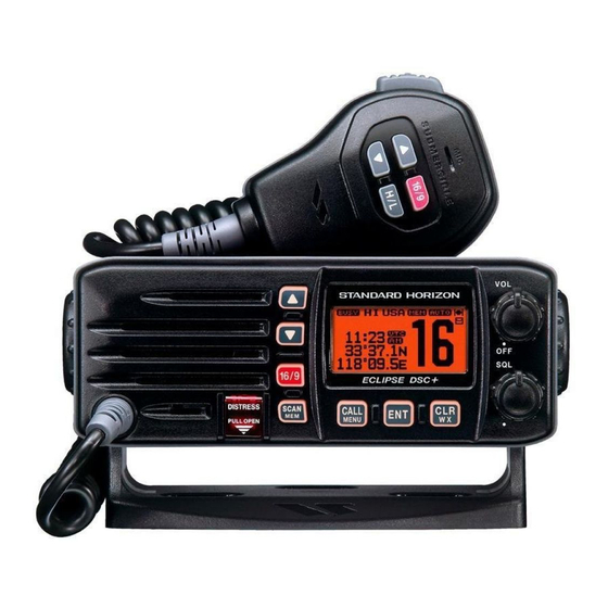
ECLIPSE DSC+ GX1100E
25 Watt VHF/FM
Class D DSC Marine Transceiver
Owner's Manual
Affordable Ultra Compact Fixed Mount VHF radio
Submersible IPX7 Front Panel
DSC (Digital Selective Calling) Class D with Position Report and Re-
quest
Programmable Scan, Priority Scan, and Dual Watch
Dot Matrix Display of various indication includes the GPS Latitude/Lon-
gitude shown
Simple Operation
All USA / International and Canadian Marine Channels
When Attached to GPS Receiver
GX1100E
Page 1
Advertisement
Table of Contents

Related Manuals for Standard Horizon Eclipse DSC+ GX1100E


Summary of Contents for Standard Horizon Eclipse DSC+ GX1100E
- Page 1 ECLIPSE DSC+ GX1100E 25 Watt VHF/FM Class D DSC Marine Transceiver Owner's Manual Affordable Ultra Compact Fixed Mount VHF radio Submersible IPX7 Front Panel DSC (Digital Selective Calling) Class D with Position Report and Re- quest Programmable Scan, Priority Scan, and Dual Watch...
-
Page 2: Table Of Contents
TABLE OF CONTENTS 1 GENERAL INFORMATION ................... 4 2 PACKING LIST ..................... 4 3 OPTIONS ......................4 4 INSTALLATION NOTE ..................5 5 GETTING STARTED ..................... 6 ABOUT VHF RADIO ................. 6 SELECTING AN ANTENNA ..............6 COAXIAL CABLE ..................7 6 INSTALLATION ..................... - Page 3 TABLE OF CONTENTS 9 DIGITAL SELECTIVE CALLING ................. 24 GENERAL ....................24 MARITIME MOBILE SERVICE IDENTITY (MMSI) ........24 9.2.1 What is an MMSI? ................24 9.2.2 Programming the MMSI ..............25 DISTRESS ALERT ................... 26 9.3.1 Tansmitting a Distress Alert ............26 9.3.2 Receiving a Distress Alert ............
-
Page 4: General Information
1 GENERAL INFORMATION The Vertex Standard GX1100E ECLIPSE DSC+ is a VHF/FM transceiver de- signed for use in the frequency range of 156.025 to 163.275 MHz. The GX1100E can be operated from 10.8 to 15.6 VDC and has a switchable RF output power of 1 watt or 25 watts. -
Page 5: Installation Note
4 INSTALLATION NOTE The installation of this equipment should be made in such a manner as to re- spect the EC recommended electromagnetic field exposure limits (1999/519/ EC). The maximum RF power available from this device is 25 watts. The antenna should be installed as high as possible for maximum efficiency and that this installation height should be at least 5 meters above ground (or accessible) level. -
Page 6: Getting Started
5 GETTING STARTED 5.1 ABOUT VHF RADIO The radio frequencies used in the VHF marine band lie between 156 and 158 MHz with some shore stations available between 161 and 163 MHz. The ma- rine VHF band provides communications over distances that are essentially “line of sight”... -
Page 7: Coaxial Cable
5.3 COAXIAL CABLE VHF antennas are connected to the transceiver by means of a coaxial cable – a shielded transmission line. Coaxial cable is specified by it’s diameter and construction. For runs less than 6 m, RG-58/U, about 6 mm in diameter is a good choice. For runs over 6 m but less than 15 m, the larger RG-8X should be used for cable runs over 15 m RG213 should be used. -
Page 8: Installation
6 INSTALLATION 6.1 LOCATION The radio can be mounted at any angle. Choose a mounting location that: • keeps the radio and microphone at least 1 m away from your vessel’s magnetic navigation compass • provides accessibility to the front panel controls •... -
Page 9: Optional Mmb-84 Flash Mount Bracket
6.2.2 Optional MMB-84 Flush Mount Bracket 1. To assist in flush mounting, a template has been included. Use this tem- plate to assess the mounting location. 2. Use the template to mark the location where the rectangular hole is to be cut. -
Page 10: Electrical Connections
6.3 ELECTRICAL CONNECTIONS CAUTION Reverse polarity connections will damage the radio! Connect the power cord and antenna to the radio. Antenna and Power Supply connections are as follows (see Figure 1): 1. Mount the antenna at least 1 m away from the radio. At the rear of the radio, connect the antenna cable. -
Page 11: Accessory Cable
Input: GLL, GGA, RMC and GNS (RMC sentence is recommended) Output: DSC and DSE (DSC sentences to Standard Horizon Plotter for Position Polling) 6.5 CHECKING GPS CONNECTIONS After connections have been made between the GX1100E and the GPS, a small satellite icon will ap-... -
Page 12: Changing The Gps Time
6.6 CHANGING THE GPS TIME From the Factory the GX1100E shows GPS satellite time or UTC time. A time offset is needed to show the local time in your area. 1. Press and hold down the [ CALL ( MENU )] key until “SETUP MENU SETUP MENU”... -
Page 13: Changing The Time Location
6.7 CHANGING THE TIME LOCATION Sets the radio to show UTC time or Local time with the offset inputted in section 6.6 Changing the GPS Time. 1. Press and hold down the [ CALL ( MENU )] key until “SETUP MENU SETUP MENU”... -
Page 14: Controls And Indicators
7 CONTROLS AND INDICATORS NOTE This section defines each control of the transceiver. See Figure 4 for location of controls. For detailed operating instructions refer to section “8 BASIC OPERATION.” POWER SWITCH / VOLUME CONTROL ( VOL/PWR ) Turns the transceiver on and off as well as adjusts the audio volume. Turn this knob clockwise to turn the radio on and increase the speakers audio volume level. - Page 15 Figure 4. Controls and Connectors GX1100E Page 15...
- Page 16 KEYPAD [ ( UP )] / [ ( DOWN )] KEYS The [ ( UP )] and [ ( DOWN )] keys are used to select a desired chan- nel and to select items in the DSC OPERATION and SETUP menus. [ 16/9 ] Key Immediately recalls channel 16 from any channel location and auto- matically selects high power.
- Page 17 ANTENNA JACK Connects an antenna to the transceiver. Use a marine VHF antenna with an impedance of 50 ohms. MICROPHONE Transmits the voice message with reduction of background noise, using Clear Voice Noise Reduction Technology. NOTE: Be sure your mouth is about 1.5 cm from the mic hole for best performance.
-
Page 18: Basic Operation
8 BASIC OPERATION 8.1 RECEPTION 1. After the transceiver has been installed, ensure that the power supply and antenna are properly connected. 2. Turn the VOL/PWR knob clockwise to turn the transceiver on. 3. Turn the SQL knob fully counterclockwise. This state is known as “squelch off”. 4. -
Page 19: Simplex/Duplex Channel Use
8.4 SIMPLEX/DUPLEX CHANNEL USE Refer to the VHF MARINE CHANNEL CHART (page 62) for instructions on use of simplex and duplex channels. NOTE All channels are factory-programmed in accordance with International, Industry Canada (Canada), and FCC (USA) regulations. Mode of opera- tion cannot be altered from simplex to duplex or vice-versa. -
Page 20: Calling Another Vessel (Channel 16 Or 9)
8. Give your vessel’s description: length, design (power or sail), colour and other distinguishing marks. The total transmission should not exceed 1 minute. 9. End the message by saying “OVER.” Release the microphone button and listen. 10. If there is no answer, repeat the above procedure. If there is still no re- sponse, try another channel. -
Page 21: Making Telephone Calls
8.8 MAKING TELEPHONE CALLS To make a radiotelephone call, use a channel designated for this purpose, The fastest way to learn which channels are used for radiotelephone traffic is to ask at a local marina. Channels available for such traffic are designated Public Correspondence channels on the channel charts in this manual. -
Page 22: Memory Scanning (M-Scan)
8.10.2 Memory Scanning ( M-SCAN ) 1. Adjust the SQL knob until background noise disappears. 2. Select a desired channel to be scanned using the [ ( UP )] / [ ( DOWN )] keys. 3. Press and hold the [ SCAN ( MEM )] key for one second, “MEM” will appear on the LCD which indicates the channel has been programmed into the transceivers memory. -
Page 23: Priority Channel Setting
priority channel will be scanned after each programmed channel. 7. To stop scanning, press the [ 16/9 ] or [ CLR ( WX )] key. Priority Channel Setting 1. Press and hold down the [ CALL ( MENU )] key until “SETUP MENU SETUP MENU”... -
Page 24: Digital Selective Calling
9 DIGITAL SELECTIVE CALLING 9.1 GENERAL WARNING This radio is designed to generate a digital maritime distress and safety call to facilitate search and rescue. To be effective as a safety device, this equipment must be used only within communication range of a shore- based VHF marine channel 70 distress and safety watch system. -
Page 25: Programming The Mmsi
9.2.2 Programming the MMSI WARNING A User MMSI can be input only once. Therefore, please be careful not to input the incorrect MMSI number. If the user needs to change the MMSI number after it has been entered, the radio will have to be returned to Factory Service. -
Page 26: Distress Alert
9.3 DISTRESS ALERT The GX1100E is capable of transmitting and receiving DSC Distress messages to all DSC radios. The GX1100E may be connected to a GPS to also transmit the Latitude and Longitude of the vessel. 9.3.1 Transmitting a Distress Alert NOTE To be able to transmit a Distress Alert an MMSI number must be pro- grammed, refer to section “9.2.2 Programming the MMSI.”... - Page 27 Transmitting a Distress Alert with Nature of Distress The GX1100E is capable of transmitting a Distress Alert with the following “Na- ture of Distress” categories: Undesignated, Fire, Flooding, Collision, Grounding, Capsizing, Sinking, Adrift, Abandoning, Piracy, Mob 1. Lift the red spring loaded DISTRESS cover and press the [ DISTRESS ] key.
-
Page 28: Receiving A Distress Alert
9.3.2 Receiving a Distress Alert 1. When a Distress Alert is received, an emergency alarm sounds. The display will show the MMSI (or name) of the vessel transmitting the Distress and the radio au- tomatically switches to channel 16. 2. Press any key to stop the alarm. 3. - Page 29 MEMO GX1100E Page 29...
-
Page 30: All Ships Call
9.4 ALL SHIPS CALL The All Ships Call function allows contact to be established with other vessel stations without having their ID in the individual calling directory. Also, priority for the call can be designated as Urgency or Safety. URGENCY Call: This type of call is used when a vessel may not truly be in distress, but have a potential problem that may lead to a dis- tress situation. -
Page 31: Receiving An All Ships Call
9.4.2 Receiving an All Ships Call 1. When an All Ships Call is received, an emergency alarm sounds. The display will show the MMSI (or name) of the vessel transmitting the All Ships Call and the radio automatically switches to the requested channel (but, the display will not change). -
Page 32: Individual Call
9.5 INDIVIDUAL CALL This feature allows the GX1100E to contact another vessel with a DSC VHF radio and automatically switch the receiving radio to a desired communications channel. This feature is similar to calling a vessel on CH16 and requesting to go to another channel (switching to the channel is private between the two stations). -
Page 33: Setting Up Individual Ringer
ber and move one space to the right press the [ ENT ] key. Repeat this proce- dure until all nine spaces of the MMSI number are entered. 11. If a mistake was made entering in the name or the MMSI number repeat pressing the microphone’s [ H/L ] key until the wrong character is selected, then press the [ ( UP )] / [ ( DOWN )] keys to correct the entry. -
Page 34: Setting Up Individual / Group Call Ringer
9.5.3 Setting up the Individual/Group Call Ringer When a Individual Call or Group Call is received the radio will produce a ringing tone for 3 minutes. This selection allows the Individual Call ringer time to be changed. 1. Press and hold down the [ CALL ( MENU )] key until “SETUP MENU SETUP MENU”... -
Page 35: Transmitting An Individual Call
9.5.4 Transmitting an Individual Call This feature allows the user to contact another vessel with a DSC radio. This feature is similar to calling a vessel on CH16 and requesting to go to another channel. Pre-Programmable Calling 1. Press the [ CALL ( MENU )] key. The “DSC MENU DSC MENU DSC MENU DSC MENU”... - Page 36 Manual Calling You may enter an MMSI number manually to contact without storing it in the Individual Directory. 1. Press the [ CALL ( MENU )] key. The “DSC MENU DSC MENU DSC MENU DSC MENU” DSC MENU will appear. 2.
-
Page 37: Receiving An Individual Call
9.5.5 Receiving an Individual Call When receiving an individual call, an acknowledgment must be sent back to the calling station. The GX1100E default setting is Automatic, but has a selection that allows you to manually send a reply before the radio will switch to the requested calling channel. -
Page 38: Call Waiting Directory
9.6 CALL WAITING DIRECTORY The GX1100E logs received Distress Calls and Individual Calls into the Call Waiting Directory for review at a later time. The DSC Call Waiting feature is similar to an answer machine where calls are recorded for review. When a call is logged while the radio is set on the DSC Standby function, a “... -
Page 39: To Delete The Received Log From The "Dsc Log" Directory
[ ( DOWN )] keys to review details for the selected category or station. 6. If you review the DSC Call, press the [ ENT ] key again, to call the selected station if de- sired. 7. To exit Call Waiting Directory and return to radio operation mode press the [ CLR ] key. -
Page 40: Group Call
9.7 GROUP CALL This feature allows the user to contact a group of specific vessels (example members of a yacht club) with a group MMSI number using the Group call function to automatically switch to a desired channel for voice communications. 9.7.1 Setting up a Group Call For this function to operate the same Group MMSI must be programmed into all the DSC VHF radios within the group of vessels that will be using this fea-... -
Page 41: Transmitting A Group Call
key. Repeat this procedure until all nine space of the MMSI number are entered. 11. If a mistake was made entering in the name or the MMSI number repeat pressing the microphone’s [ H/L ] key until the wrong character is selected, then move the channel knob to correct the entry. - Page 42 Manual Calling You may enter an MMSI number manually to contact without the Setting up the Group call number. 1. Press the [ CALL ( MENU )] key. The “DSC MENU” will appear. MENU MENU MENU MENU 2. Press the [ ( UP )] / [ ( DOWN )] keys to se- GROUP”.
-
Page 43: Receiving A Group Call
9.7.3 Receiving a Group Call 1. When a group call is received, the GX1100E will produce a ringing alarm sound. The display will show the MMSI (or name) of the vessel transmitting the Group Call and the radio automatically switches to the requested channel (but, the display will not change). -
Page 44: Position Request
GX1100E. Standard Horizon has taken this feature one step further, if any Standard Hori- zon GPS is connected to the GX1100E, the polled position of the vessel is shown on the display of the GPS chart plotter making it easy to navigate to the location of the polled vessel. -
Page 45: Transmitting A Position Request To Another Vessel
The GX1100E has the capability to turn off the Position Request ringer. 1. Press and hold down the [ CALL ( MENU )] key until “SETUP MENU SETUP MENU” appears. SETUP MENU SETUP MENU SETUP MENU 2. Press the [ ( UP )] / [ ( DOWN )] keys to se- lect “DSC SETUP DSC SETUP”... - Page 46 8. Press the [ ( DOWN )] key to show the position from the polled vessel transferred on the display. 9. If the GX1100E does not receive a reply, the dis- play will be as shown in the illustration on the right. To send again, press the [ ENT ] key.
-
Page 47: Receiving A Position Request
alarm sound and the position from the polled vessel transferred to the GPS Chart plotter. 10. Press any key to stop the alarm. 11. Press the [ ( DOWN )] key to show the po- sition from the polled vessel transferred on the dis- play. -
Page 48: Position Report
9.9 POSITION REPORT The feature is similar to Position Request, however instead of requesting a position of another vessel this function allows you to send your position to an- other vessel. In order to send your position you need to have a GPS receiver connected or to have manually input your position. -
Page 49: Transmitting A Dsc Position Report Call
9.9.2 Transmitting a DSC Position Report Call Pre-Programmable Calling 1. Press the [ CALL ( MENU )] key. The “DSC MENU” will appear in the display. MENU MENU MENU MENU 2. Press the [ ( UP )] / [ ( DOWN )] keys to se- lect the “POS REPORT POS REPORT POS REPORT... -
Page 50: Receiving A Dsc Position Report Call
Transfer the received data to any Standard Horizon GPS Chart plotter if connected. 2. Press any key to stop ringing. 3. Press the [ ( UP )] / [ ( DOWN )] keys to change the display to view the received data. -
Page 51: Dsc Transmission Test
9.10 DSC TRANSMISSION TEST 1. Press the [ CALL ( MENU )] key. The “DSC MENU DSC MENU DSC MENU DSC MENU” DSC MENU will appear in the display. 2. Press the [ ( UP )] / [ ( DOWN )] keys to select the “DSC TEST DSC TEST DSC TEST... -
Page 52: Manual Inputting Of The Gps Location (Lat/Lon)
9.11 MANUAL INPUTTING OF THE GPS LOCATION ( LAT/LON ) You may send the Latitude/Longitude of your vessel manually even if the GX1100E is not connected the GPS receiver unit. After the position is entered, transmitting a DSC Distress, Position Request, or Position Send will contain the manually entered position. -
Page 53: Radio Setup Mode
10 RADIO SETUP 10.1 LAMP ADJUSTING Allows adjustment of the backlight intensity or to turn it off. 1. Press and hold down the [ CALL ( MENU )] key until “SETUP MENU SETUP MENU” appears. SETUP MENU SETUP MENU SETUP MENU 2. -
Page 54: Time Offset
10.3 TIME OFFSET This selection sets the time offset between local time and UTC (time GPS sends to radio). 1. Press and hold down the [ CALL ( MENU )] key until “SETUP MENU SETUP MENU” appears. SETUP MENU SETUP MENU SETUP MENU 2. -
Page 55: Time Display
10.4 TIME DISPLAY This selection selects the time display between local time and UTC (time GPS sends to radio). 1. Press and hold down the [ CALL ( MENU )] key until “SETUP MENU SETUP MENU” appears. SETUP MENU SETUP MENU SETUP MENU 2. -
Page 56: Scan Type
10.6 SCAN TYPE This selection selects the scan mode between “Memory Scan” and “Priority Scan.” 1. Press and hold down the [ CALL ( MENU )] key until “SETUP MENU SETUP MENU” appears. SETUP MENU SETUP MENU SETUP MENU 2. Press the [ ENT ] key, then select “SCAN TYPE SCAN TYPE”... -
Page 57: Programming The Atis Code
11 PROGRAMMING THE ATIS CODE A ten digit ATIS code is used for an automatic transmitter identification system in inland water ways in various countries in Europe. The GX1100E transmit the ATIS code at the end of every transmission, which is monitored by marine coast sta- tions. - Page 58 11. Press the [ ( UP )] key to enable the ATIS (an “OFF OFF” notation will replace the “ON ON” notation), then press the [ ENT ] key. 12. Repeat steps 10 and 11 for other “mode”, if neces- sary.
-
Page 59: Maintenance
Ensure that the supply voltage to the transceiver does not exceed 16 VDC or fall below 11 VDC. • Use only STANDARD HORIZON-approved accessories and replacement parts. In the unlikely event of serious problems, please contact your Dealer or our repair facility. -
Page 60: Troubleshooting Chart
12.3 TROUBLESHOOTING CHART SYMPTOM PROBABLE CAUSE REMEDY Transceiver fails to No DC voltage to the a. Check the 12VDC battery connections and power up. transceiver, or blown the fuse. fuse. b. The PWR key needs to be rotated clockwise to turn the radio on. Transceiver blows fuse R e v e r s e d p o w e r Check the power cable for DC voltage, or re-... -
Page 61: Channel Assignments
13 CHANNEL ASSIGNMENTS Tables on the following columns list the VHF Marine Channel assignments for U.S.A. and International use. Below are listed some data about the charts. 1. VTS. Where indicated, these channels are part of the U.S. Coast Guard’s Vessel Traffic System. - Page 62 VHF MARINE CHANNEL CHART CHANNEL USE D 156.050 160.650 Public Correspondence (Marine Operator) 156.050 Port Operation and Commercial. VTS in selected areas D 156.100 160.700 Public Correspondence (Marine Operator) D 156.150 160.750 Public Correspondence (Marine Operator) 156.150 U.S. Government Only, Coast Guard D 156.200 160.800 Public Correspondence (Marine Operator), Port operation, ship movement 156.200...
- Page 63 VHF MARINE CHANNEL CHART CHANNEL USE D 156.025 160.625 Public Correspondence (Marine Operator) D 156.075 160.675 Public Correspondence (Marine Operator), Port operation, ship movement 156.075 Public Coast: Coast Guard; East Coast: commercial fishing only D 156.125 160.725 Public Correspondence (Marine Operator), Port operation, ship movement 156.125 Public Coast: Coast Guard;...
- Page 64 VHF MARINE CHANNEL CHART CHANNEL USE D 157.025 161.625 Port operation, ship movement 157.025 Commercial D 157.075 161.675 Port operation, ship movement 157.075 U.S. Government Only - Environmental protection operations. 157.075 Canadian Coast Guard Only D 157.125 161.725 Public Correspondence (Marine Operator), Port operation, ship movement 157.125 U.S.
-
Page 65: Specifications
14 SPECIFICATIONS Performance specifications are nominal, unless otherwise indicated, and are subject to change without notice. 14.1 GENERAL Channels ............. All USA, International and Canadian Input Voltage ..........12.0 VDC +30% / –10% (10.8 ~ 15.6 VDC) Current Drain Standby ......................0.3 A Receive ...................... - Page 66 14.4 GX1100E DIMENSIONS Page 66 GX1100E...
-
Page 67: Declaration Of Conformity
We, Yaesu UK Ltd. declare under our sole responsibility that the following equipment complies with the essential requirements of the Directive 1999/5/EC. Type of Equipment: VHF Transceiver Brand Name: STANDARD HORIZON Model Number: GX1100E Manufacturer: Vertex Standard Co., Ltd. Address of Manufacturer:... - Page 68 Copyright 2009 VERTEX STANDARD CO., LTD. 4-8-8 Nakameguro, Meguro-Ku, Tokyo 153-8644, Japan VERTEX STANDARD CO., LTD. VERTEX STANDARD All rights reserved. US Headquarters 10900 Walker Street, Cypress, CA 90630, U.S.A. No portion of this manual YAESU UK LTD. may be reproduced Unit 12, Sun Valley Business Park, Winnall Close without the permission of Winchester, Hampshire, SO23 0LB, U.K.