Table of Contents
Advertisement
This Manual is Bookmarked
Operating Instructions and Parts Manual
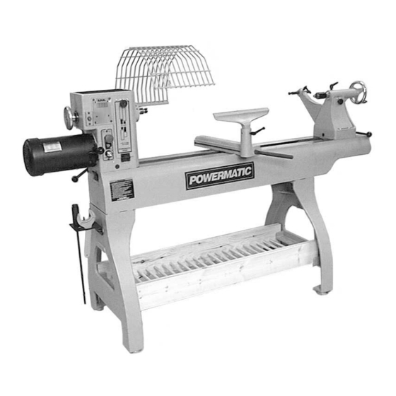
Woodturning Lathe
Model 3520B
shown with optional 18-inch bed extension and user-made shelf
WMH TOOL GROUP
2420 Vantage Drive
Elgin, Illinois 60124
Part No. M-1352001
Ph.: 800-274-6848
Revision A1 8/06
www.wmhtoolgroup.com
Copyright © WMH Tool Group
Advertisement
Table of Contents

Related Manuals for Powermatic 3520B


Summary of Contents for Powermatic 3520B
- Page 1 This Manual is Bookmarked Operating Instructions and Parts Manual Woodturning Lathe Model 3520B shown with optional 18-inch bed extension and user-made shelf WMH TOOL GROUP 2420 Vantage Drive Elgin, Illinois 60124 Part No. M-1352001 Ph.: 800-274-6848 Revision A1 8/06 www.wmhtoolgroup.com...
-
Page 2: Warranty And Service
This warranty covers only the initial purchaser of the product. WHAT IS THE PERIOD OF COVERAGE? The general POWERMATIC warranty lasts for the time period specified in the product literature of each product. WHAT IS NOT COVERED? The Five Year Warranty does not cover products used for commercial, industrial or educational purposes. Products with a Five Year Warranty that are used for commercial, industrial or education purposes revert to a One Year Warranty. -
Page 3: Table Of Contents
Face Plate and Bowl Turning...25 Bowl Turning Techniques ...26 Maintenance...27 Indexer Positions ...28 Troubleshooting...29 Recommended Lathe Speeds (per diameter of workpiece)...30 Replacement Parts ...30 Headstock Assembly...31 Parts List: Headstock Assembly ...32 Stand and Bed Assembly ...34 Parts List: Stand and Bed Assembly...35 Optional Accessories: Bed Extensions...36... -
Page 4: Warning
4. This Lathe is designed and intended for use by properly trained and experienced personnel only. If you are not familiar with the proper and safe operation of a Lathe, do not use until proper training and knowledge have been obtained. - Page 5 32. Adjust the tool support to the proper height and position for the work. Rotate the workpiece by hand to check clearance with the tool support. 33. Select the appropriate speed for the turning job at hand. Start at low speed and allow the Lathe to ramp up to operating speed.
-
Page 6: Introduction
This manual is provided by WMH Tool Group covering the safe operation and maintenance procedures for a Model 3520B Lathe. This manual contains instructions on installation, safety precautions, general operating procedures, maintenance instructions and parts breakdown. This machine has been designed and constructed to provide years of trouble free operation if used in accordance with instructions set forth in this manual. -
Page 7: Unpacking
Open shipping container and check for shipping damage. Report any damage immediately to your distributor and shipping agent. Do not discard any shipping material until the Lathe is assembled and running properly. Compare the contents of your container with the following parts list to make sure all parts are intact. -
Page 8: Assembly
If you have a hoist or forklift: 3. Lift the Lathe off the pallet using a forklift or hoist, and move it to the desired location. (Forks may need to be positioned more toward the headstock to balance the weight.) Proceed to step 6 to install the legs... -
Page 9: Comparator Rear Bracket
Installing and Using” for further information.) Tool Caddy The tool caddy, shown in Figure 3, can be mounted to the left end or right end of the Lathe. The left end, near the headstock area, is generally preferred for convenience. Use two... -
Page 10: Bed Extension (Optional Accessory)
Bed Extension (Optional Accessory) An optional 18” bed extension assembly, stock number 6294727B, is available for the Lathe (see your Powermatic dealer). To mount the bed extension to the Lathe: 1. Slide the tailstock away from the edge of the bed. -
Page 11: Shelf Assemblies (Optional)
18” bed extension to the three lower holes on the Lathe frame, and (2) mount a vertical extension post [optional accessory, stock number 3520B-310] to the tool rest base. See Figure 9. Shelf Assemblies (Optional) The double ledges on the inside of the Lathe... -
Page 12: Grounding Instructions
1. Mark your hole centers (2” centers) along the length of a 2x6. Place the holes so that the tops of the dowels will be even with the tops of the ledges on the Lathe. Also, adjust your hole centers as necessary so that the first... -
Page 13: Single Phase Operation
Repair or replace a damaged or worn cord immediately. The Lathe will operate on single phase or three phase, 230 volt power supply. The Lathe should be connected to a dedicated circuit. Make sure the characteristics of your power supply match the specifications on the motor plate of the Lathe. -
Page 14: Cam Tightness
Figure 15 uses the tailstock as the example: 1. Unscrew and remove the stop bolt on the end of the lathe bed (B, Figure 14) and slide the tailstock off the end of the bed. 2. Turn the tailstock on its side, and tighten the lock nut with a wrench. -
Page 15: Live Center And Cone
Indexer The indexer allows you to cut evenly spaced features in a workpiece while keeping the Lathe headstock spindle locked; for example, when cutting flutes on a spindle blank with a router, while the spindle blank is secured within the Lathe centers. -
Page 16: Face Plate - Installing And Removing
Comparator – Installing and Using spindle comparator consists comparator centers inserted into the brackets at the back of the Lathe. The comparator is used to mount a finished, or “reference spindle” from which measurements measurements being transferred to the new piece which is being turned. -
Page 17: Speed Change
Likewise, when turning operation is complete, remove the reference spindle first. Speed Change 1. Disconnect Lathe from power source. 2. To change speed ranges, pull open the access door on the headstock. 3. Loosen the pivot lock handle (A, Figure 25) and lift up the tension handle (B, Figure 25) to raise the motor. -
Page 18: Sheave And Belt Alignment
Run the lathe for a time, and check for heat from the spindle bearings. If the bearings are running hot, the spanner nut is too tight and should be loosened slightly. -
Page 19: Operating Controls
1. Disconnect Lathe from power source. 2. Loosen the pivot lock handle (A, Figure 25) and lift up the tension handle (B, Figure 25) to raise the motor. 3. Tighten the pivot lock handle (A, Figure 25) to hold the motor in the raised position. Slip the belt off the pulleys. -
Page 20: Operation
A.C. Inverter (mounted to rear of headstock) The 3520B Lathe uses the latest technology in A.C. inverter drives to provide infinitely variable spindle speeds within the specified ranges (shown under “Specifications”... -
Page 21: Turning Tools
(for shaping) and a 100- grit alum. oxide wheel (for final sharpening and touchup). The grinder should be located near your lathe and at a comfortable height. A diamond dresser will keep the wheels true and eliminate glazing. -
Page 22: Spindle Turning
Spindle Turning Spindle turning takes place between the centers of the lathe. It requires a spur or drive center in the headstock and a live or dead center in the tailstock. A cup center rather than a cone center in the tailstock will often reduce the risk of splitting the stock. -
Page 23: Cutting Techniques
Lathe bed. 11. Rotate workpiece by hand to check for proper clearance. 12. Start lathe at lowest speed and bring it up to the appropriate RPM for the size of workpiece used. Consult digital readout on the headstock. - Page 24 To apply a finish, the workpiece can be left on the lathe. Turn off the lathe and use a brush or paper towel to apply the finish. Remove excess finish before restarting lathe. Allow to dry and sand again with 320 or 400 grit sandpaper.
-
Page 25: Face Plate And Bowl Turning
Face Plate and Bowl Turning Face plate turning is normally done on the inboard side of the headstock over the bed. Larger workpieces must be turned on the outboard side (remove tailstock and tool support base, and move headstock to opposite end of bed). -
Page 26: Bowl Turning Techniques
4. Turn workpiece by hand to ensure proper clearance. 5. Start lathe at lowest speed and bring it up to the maximum safe speed for the size of work to be turned (see page 30). If the machine starts to vibrate, lower the speed until vibration stops. -
Page 27: Maintenance
Failure to comply may cause serious injury. Maintenance on the 3520B Lathe should be performed at periodic intervals to ensure that the machine is in proper working order, that all... -
Page 28: Indexer Positions
How to use the chart The indexer is shown as viewed from the tailstock end of the Lathe. Points A, B, C and D are the holes in the head casting. The holes in the spindle collar may be considered as numbered 1 through 12. -
Page 29: Troubleshooting
Apply only sufficient force with tailstock to hold workpiece securely in place. Tighten cam lock nut (Figure 15). Remove tailstock and clean surfaces with a cleaner/degreaser. Re-apply light coat of oil to Lathe bed surface. -
Page 30: Recommended Lathe Speeds (Per Diameter Of Workpiece)
Recommended Lathe Speeds DIAMETER OF WORK ROUGHING RPM Under 2" 2 to 4" 4 to 6" 6 to 8" 8 to 10" 10 to 12" 12 to 14" 14 to 16" 16" to 20" 20" to 24" Replacement Parts Replacement parts are listed on the following pages. To order parts or reach our service department, call 1-800-274-6848 between 7:30 a.m. -
Page 31: Headstock Assembly
Headstock Assembly... -
Page 32: Parts List: Headstock Assembly
20 ...JWL1642-164A ... Inverter, VFD015S21A... 2HP, 220V ... 1 21 ...6710015... Socket Head Cap Screw... #10-24x1/2” ... 10 22 ...JWL1642-170... Signal Cord..1 23 ...3520B-223 ... Headstock Clamping Shaft..1 24 ...TS-0640091 ... Nylon Lock Hex Nut ... 3/8”-16... 1 25 ...6095038... Bushing ..1 26 ...6430045... - Page 33 92 ...3520B-292 ... Brass Tip ..1 93 ...3520B-293 ... Inverter Label..2 94 ...3520B-294 ... Warning Label ..1 95 ...3520B-295 ... Cord Snap Ring ..1 96 ...3520B-296 ... Phillips Pan Head Machine Screw... M3-0.5Px10 ... 3...
-
Page 34: Stand And Bed Assembly
Stand and Bed Assembly... -
Page 35: Parts List: Stand And Bed Assembly
3...6295754... Stop Bolt..2 ...6294797... Tool Rest Support Assembly (includes index #4 thru #12) ... 1 4...3520B-104 ... Tool Rest Support Base ..1 5...3520B-105 ... End Cover ..1 6...3520B-106 ... C-Ring ... S-22 ... 1 7...6710015... -
Page 36: Optional Accessories: Bed Extensions
...6294727B ... 18” Bed Extension Assembly (includes items 1 thru 6) 1...3520B-310 ... Extension Post..1 2...6294763... Locking Handle..1 3...3520B-311 ... 18” Bed Extension ..1 4...TS-0680042 ... Flat Washer ... 3/8”... 3 5...TS-0720091 ... Lock Washer... 3/8”... 3 6...TS-0209081 ... -
Page 37: Optional Accessories: Outboard Turning Stand
Optional Accessories: Outboard Turning Stand Index No. Part No. Description Size Qty..6294732... Heavy Duty Outboard Turning Stand Assembly (items 1 thru 7) ... 1...3042503... Turning Stand Base ..1 2...6295897... Offset Tool Support Pin...1.00” diameter... 1 3...6295898... Offset Tool Support Casting...1.00” hole... 1 4...2695026... -
Page 38: Optional Accessories: Adapters, Face Plates, And Tool Supports
Optional Accessories: Adapters, Face Plates, and Tool Supports Index No. Part No. Description 1...6294734... Spindle Adapter ...1-1/4”-8 to 1-1/2”-8 ... 2...6294735... Spindle Extension ...2” ... 3...6294745... Ball Bearing Tailstock Center (not shown) ... 4...6294736... 3” Face Plate ...1-1/4-8 ... 5...6294737... 4” Face Plate ...1-1/4-8 ... 6...6294738... -
Page 39: Optional Accessories: Dust Port Assembly
2...3520B-402 ... Upper Dust Hood ..1 3...3520B-403 ... Hood Lock Knob (Female) ..1 4...3520B-404 ... Lock Washer, External Tooth ... M7 ... 2 5...3520B-405 ... Hood Support Collar ..1 6...3520B-406 ... Hood Lock Knob ..3 7...3520B-407 ... -
Page 40: Electrical Connections
Electrical Connections... -
Page 41: Electrical: Remote On/Off Switch (Optional Accessory)
5. Reinstall the control panel to the headstock. From the back of the headstock, lightly pull out any excess wire that may be inside the headstock. 6. The magnetic back on the remote switch will allow the switch to be placed anywhere on the Lathe. 7. Connect electrical power to the Lathe and resume operations. - Page 42 NOTES...
- Page 44 WMH Tool Group 2420 Vantage Drive Elgin, Illinois 60124 Phone: 800-274-6848 www.wmhtoolgroup.com...