Table of Contents
Advertisement
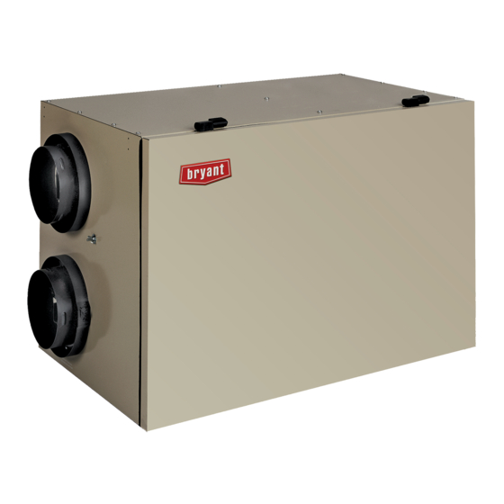
HRVXXLHB
HRVXXLHB Unit
These
ENERGY STAR
energy efficiency guidelines set by
Natural Resources Canada and
the US EPA. They meet ENERGY
STAR requirements only when
used in Canada.
Installation Instructions
A05260
products
earned
the
by meeting strict
®
Heat Recovery Ventilator
INTRODUCTION
The Heat Recovery Ventilator (HRV) is used to exchange indoor
stale air with outside fresh air. The HRV unit is equipped with a
special heat recovery core which transfers sensible heat between
the fresh incoming air and stale exhaust air.
It is required to locate the HRV in a conditioned space. Special
attention should be given to condensate drain, duct application,
balancing the HRV, and locating unit for easy access and routine
maintenance. The cross- flow design core allows entering and
leaving air streams to transfer heat energy without mixing.
NOTE: Read the entire instruction manual before starting the
installation.
SAFETY CONSIDERATIONS
Improper installation, adjustment, alteration, service, maintenance,
or use can cause explosion, fire, electrical shock, or other
conditions which may cause death, personal injury or property
damage. Consult a qualified installer, service agency or your
distributor or branch for information or assistance. The qualified
installer or agency must use factory- authorized kits or accessories
when modifying this product. Refer to the individual instructions
packaged with the kits or accessories when installing.
Follow all safety codes. Wear safety glasses, protective clothing,
and work gloves. Have a fire extinguisher available. Read these
instructions thoroughly and follow all warnings and cautions
included in literature and attached to the unit. Consult local
building codes and the current edition of the National Electrical
Code (NEC) NFPA 70.
In Canada, refer to the current editions of the Canadian Electrical
Code CSA C22.1.
Recognize safety information. When you see this symbol
the unit and in instructions or manuals, be alert to the potential for
personal injury. Understand the signal words DANGER,
WARNING, and CAUTION. These words are used with the
safety- alert symbol. DANGER identifies the most serious hazards,
which will result in severe personal injury or death. WARNING
signifies hazards, which could result in personal injury or death.
CAUTION is used to identify unsafe practices, which may result
in minor personal injury or product and property damage. NOTE
is used to highlight suggestions which will result in enhanced
installation, reliability, or operation.
on
Advertisement
Table of Contents

Related Manuals for Carrier HRVXXLHB


Summary of Contents for Carrier HRVXXLHB
-
Page 1: Installation Instructions
HRV, and locating unit for easy access and routine maintenance. The cross- flow design core allows entering and leaving air streams to transfer heat energy without mixing. A05260 HRVXXLHB Unit NOTE: Read the entire instruction manual before starting the installation. SAFETY CONSIDERATIONS... -
Page 2: Typical Installations
TYPICAL INSTALLATIONS NOTE: Installation may vary according to the model number and the position; normal or reverse in which the unit is installed. There are three common installation methods. Fully Ducted System (Primarily for homes with radiant hot water or electric baseboard heating.) See Fig. -
Page 3: Component Description
COMPONENT DESCRIPTION UNIT INSTALLATION LOCATION The following listed items are components of HRVXXLHB. See Fig.4. Inspect Equipment Move carton to final installation location. Remove the HRV from carton taking care not to damage unit. Remove all packaging and inspect unit for damage. Remove parts bag from inside unit. File claim with shipping company if shipment is damaged or incomplete. - Page 4 Calculating the Duct Size Use the table below to ensure that the ducts you intend to install will be carrying air flows at or under the recommended values. Avoid installing ducts that will have to carry air flows near the maximum values and never install a duct if its air flow exceeds the maximum value.
- Page 5 4˝ 5˝ 4˝ 4˝ø 5˝ 5˝ø 4˝ø 4˝ø 5˝ø 4˝ 4˝ 6˝ø 4˝ 6˝ 6˝ø 6˝ø 6˝ 6˝ 6˝ 7˝ 7˝ 6˝ø 6˝ø 7˝ø 7˝ø A12289 Fig. 9 - Example of a design for a fully ducted system for a unit having a high speed performance of 222 cfm Installing the Ductwork and the Registers FRESH AIR DISTRIBUTION: WARNING...
- Page 6 S Make sure that the HRV/ERV duct forms an elbow inside the furnace ductwork. S If desired, interlock (synchronize) the furnace blower operation with the HRV/ERV operation. INIMUM METHOD 2: RETURN SIDE CONNECTION 18’’ (0.5 S Cut an opening into the furnace return duct not less than 10 feet (3.1 m) from the furnace (A+B).
-
Page 7: Installing The Exterior Hoods
CONNECTING THE UNIT TO THE INSULATED FLEXIBLE DUCTS VJ0091 LACE FLEXIBLE DUCT OVER LUMINUM DUCT TAPE ON IE WRAP ON DUCT TAPE NSULATION TUCKED BETWEEN APOR BARRIER AND PORT INNER PORT RING FLEXIBLE DUCT INNER AND OUTER RINGS STRAP OVER THE OUTER RING 1"... - Page 8 Connecting the Drain (HRV Units Only) Integrated Control Cut 2 sections of the plastic tube, about 12- in (305 mm) long, and All units are equipped with an integrated control, located in front attach them to each inner drain fitting, located under the unit. Join of the electrical compartment.
-
Page 9: Electrical Connection To Optional Wall Control
Once the wall control(s) connections have been made, insert the terminal connector in the electrical compartment front face. NOTE: For information about the operation of the wall controls, refer to the user guide. ERMINAL CONNECTOR LOCATION A12301 Fig. 21 - Setting Extended Defrost IMPORTANT: When installed in reverse position (upside down) in a cold region where outside temperature could drop below - 20_C (- 4_F) for more than 5 days in a row, the unit must always... - Page 10 Electrical Connection to Optional Auxiliary Wall Controls 60-MINUTE PUSH-BUTTON TIMERS DEHUMIDISTAT CRANK TIMER (5 MAXIMUM) NO C NC I OC OL Y R G B A12304 Fig. 26 - Optional Auxiliary Wall Controls NOTE: If an optional auxiliary wall control is activated and then, the Dehumidistat is being activated, this one will override the auxiliary wall control commands.
-
Page 11: Electric Connection To The Furnace
Standard furnace interlock wiring Alternate furnace interlock wiring THERMOSTAT THERMOSTAT TERMINAL 4 WIRES TERMINALS FOUR 2 WIRES WIRES heating only TWO WIRES wiring nuts heating only FURNACE FURNACE 24-VOLT 24-VOLT TERMINAL BLOCK TERMINAL BLOCK 2 WIRES TWO WIRES COOLING SYSTEM COOLING SYSTEM A11215 Fig. -
Page 12: Airflow Balancing
Defrost Cycles Tables Table 5 – HRVXXLHB1150 OUTSIDE TEMPERATURE DEFROST CYCLES (MINUTES) EXTENDED DEFROST CYCLES Operation Time Operation Time Defrosting Between Each Defrosting Between Each Celsius ( Fahrenheit ( Defrost Cycles Defrost Cycles - 15 - 27 - 17 Table 6 – HRVXXLHB1250 OUTSIDE TEMPERATURE DEFROST CYCLES (MINUTES) EXTENDED DEFROST CYCLES... -
Page 14: Care And Maintenance
CARE AND MAINTENANCE TROUBLESHOOTING WARNING WARNING ELECTRICAL SHOCK HAZARD ELECTRICAL SHOCK HAZARD Failure to follow this warning could result in personal injury Failure to follow this warning could result in personal injury or death. or death. Before installing or servicing system, always turn off, tag and Before installing or servicing system, always turn off, tag and lockout main power to system. - Page 15 Table 7 – Troubleshooting If the integrated control LED of the unit is flashing, this means the unit sensors detected a problem. See the list below to know where on the unit the problem occurs. flashes GREEN S Thermistor error. Replace the thermistor kit (double blink).
- Page 16 - 2/- 19 64.57 Catalog No: IM- HRVLHB- 01 Copyright 2012 Carrier Corp. S 7310 W. Morris St. S Indianapolis, IN 46231 Edition Date: 11/12 Replaces:NEW Manufacturer reserves the right to change, at any time, specifications and designs without notice and without obligations.