Table of Contents
Advertisement
Quick Links
Advertisement
Table of Contents

Related Manuals for Bosch RFRC-OPT


Summary of Contents for Bosch RFRC-OPT
- Page 1 RADION receiver OP RFRC-OPT Reference Guide...
-
Page 3: Table Of Contents
RADION receiver OP Table of Contents | en Table of contents Introduction About documentation Bosch Security Systems, Inc. product manufacturing dates General installation Installation workflow Unpacking information Wall tamper switch installation Magnet cover installation Complete installation Maintenance RADION receiver OP... - Page 4 Applications for this product 12.2 Installation consideration RADION universal transmitter 13.1 Installation considerations 13.2 Reed switch settings RADION keyfob 14.1 RADION keyfob FB 14.2 RADION keyfob TB RADION panic Appendices 02.2014 | 01 | F.01U.261.835 Reference Guide Bosch Security Systems, Inc...
-
Page 5: Introduction
Bosch Security Systems, Inc. product manufacturing dates Use the serial number located on the product label and refer to the Bosch Security Systems, Inc. website at http://www.boschsecurity.com/datecodes/. The following image shows an example of a product label and highlights where to find the manufacturing date within the serial number. - Page 6 | Introduction RADION receiver OP 02.2014 | 01 | F.01U.261.835 Reference Guide Bosch Security Systems, Inc...
-
Page 7: General Installation
Enroll point RF ID for wireless points Verify LED responses on devices Perform a local walk test for installed detectors Review signal strength and margin of each point Complete the installation Bosch Security Systems, Inc Reference Guide 02.2014 | 01 | F.01U.261.835... -
Page 8: Unpacking Information
This is achieved by performing an overall service walk test. Refer to your control panel documentation for system-walk, or other system-wide testing procedures. 02.2014 | 01 | F.01U.261.835 Reference Guide Bosch Security Systems, Inc... -
Page 9: Maintenance
In the normal operating mode, an alarm can be transmitted only after three (3) minutes have passed since the previous alarm restoral. This 3 minute lockout time reduces unnecessary RF transmissions in high traffic areas, thereby extending battery life. Bosch Security Systems, Inc Reference Guide 02.2014 | 01 | F.01U.261.835... -
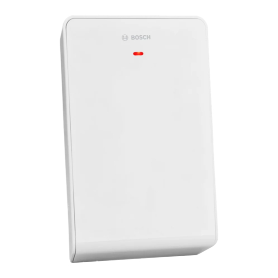
Page 10: Radion Receiver Op
Certifications and approvals Listings and approvals Europe The RFRC-OPT is EN listed for EN50131-3: 2009, EN50131-5-3: 2005 + A1: 2008, and EN50130-5 Environmental Class II. As a manufacturer of batteries or devices containing batteries, we are obliged to inform you of the following in accordance with the Battery Ordinance: –... -
Page 11: Rfrc-Opt Installation
Refer to your control panel documentation for information on the valid addresses for that control panel. The figure below shows the address switch setting for address 1. Bosch Security Systems, Inc Reference Guide 02.2014 | 01 | F.01U.261.835... -
Page 12: Base Mounting Installation
>30 mm (1.2 in). – Minimum clearance below the location where the base is mounted: >23 mm (0.9 in). 3.2.3 Wiring considerations 02.2014 | 01 | F.01U.261.835 Reference Guide Bosch Security Systems, Inc... -
Page 13: Programming Wireless Points In The Control Panel
RFID programming from a supported keypad is achieved by two methods; – Through the point source/RFID menu options, or – Enroll point RFID for wireless points – which uses the “Auto-Learn” methodology Bosch Security Systems, Inc Reference Guide 02.2014 | 01 | F.01U.261.835... -
Page 14: Enroll Point Rf Id For Wireless Points (Auto-Learn Mode)
After setup and tests are completed, and there has been no activity in the sensor’s coverage pattern for approximately 90-sec, the LED will flash to indicate that the Walk Test mode is ending. 02.2014 | 01 | F.01U.261.835 Reference Guide Bosch Security Systems, Inc... -
Page 15: Complete The Installation
3.2.8 RFRC-OPT system test Overall system test It is recommended by to test the entire system at least once every year, including the RFRC- OPT receiver by an installer to ensure proper functionality of the RADION system. -
Page 16: Specifications (Rfrc-Opt)
12 VDC nominal Maximum Current Draw 100 mA Operating Environment Functional range: -10°C to +49°C (+14°F to +120°F) EN 50130-5 Class II only: -10゚C to 40゚C (+14゚ F to +104゚F 02.2014 | 01 | F.01U.261.835 Reference Guide Bosch Security Systems, Inc... -
Page 17: Battery Requirements
Wall and Cover Tamper Switch – Transmits a tamper signal when the device is removed from its base or pulled away from the wall Table 3.3: RFRC-OPT Specifications 3.4.1 Battery requirements Notice! Dispose of used batteries according to manufacturer’s instructions. - Page 18 Quantity (Cells) RFKF-TB key fob CR2032 (coin Lithium 3 VDC RFKF-FB-key fob cell) RFPB-SB- panic CR2032 (coin Lithium 3 VDC button cell) RFPB-TB- panic button Table 3.4: Battery Requirements 02.2014 | 01 | F.01U.261.835 Reference Guide Bosch Security Systems, Inc...
-
Page 19: Radion Repeater
Ensure that the wiring used meets the following specifications: – Two-conductor unshielded wire. – The minimal requirement for wire length is 1.83 m (6 ft) from the repeater Bosch Security Systems, Inc Reference Guide 02.2014 | 01 | F.01U.261.835... -
Page 20: Specifications
Indicates an AC power failure is detected. flash pattern continuous – A communication failure within internal hardware pulse between On and components inside the receiver Off states with a short delay after the 2 pulse 02.2014 | 01 | F.01U.261.835 Reference Guide Bosch Security Systems, Inc... -
Page 21: Radion Glassbreak
Table 5.1: Specifications Installation considerations For the best detector performance, select a mounting location that is: – Mounted on the ceiling within a maximum range of 20 ft (6 m) Bosch Security Systems, Inc Reference Guide 02.2014 | 01 | F.01U.261.835... -
Page 22: Testing
Activate the tester. The sensor alarms and goes into test mode for one minute. During test mode, the LED blinks continuously. To extend test time, fire the tester at the sensor at least once a minute. 02.2014 | 01 | F.01U.261.835 Reference Guide Bosch Security Systems, Inc... - Page 23 In normal mode, the sensor will not trip to the tester, unless the tester is held next to the sensor. Each time the sensor alarms, it also goes into test mode for one minute. Room acoustics can artificially extend the range of a glassbreak sensor. Bosch Security Systems, Inc Reference Guide 02.2014 | 01 | F.01U.261.835...
-
Page 24: Hand Clap Test
Use the wall tamper tab to activate an alarm when the glass break has been removed from the wall. Maintenance Clean the cover with a damp (water) cloth as needed to keep it free of dust and dirt. Always test the sensor after cleaning it. 02.2014 | 01 | F.01U.261.835 Reference Guide Bosch Security Systems, Inc... -
Page 25: Radion Tritech
Features include: – 11m x 11m (35 ft by 35 ft) coverage – Flexible mounting height – Compatible with Bosch RADION wireless systems – Draft and Insect immune – Cover activated tamper indication. Optional wall-activated tamper is included Dimension 138.00 mm x 72.00 mm x 64.00 mm... -
Page 26: Sensitivity Settings
LED to indicate the edges of the Microwave pattern. Adjust as necessary. Please reference the LED table below for LED descriptions. LED Condition Cause Steady LED PIR activation (Walk Test) Steady green Microwave activation Steady blue Alarm signal 02.2014 | 01 | F.01U.261.835 Reference Guide Bosch Security Systems, Inc... - Page 27 Walk test from the opposite direction to determine the coverage pattern boundaries from both sides. When walk test is completed, the detector returns to normal operation after 90 sec of inactivity. Bosch Security Systems, Inc Reference Guide 02.2014 | 01 | F.01U.261.835...
-
Page 28: Radion Pir
LED activation. Each alarm will also extend the Test Mode. Adjust as necessary. Notice! Excessive use of the Walk Test Mode may reduce battery life. Use only for initial setup and maintenance testing. 02.2014 | 01 | F.01U.261.835 Reference Guide Bosch Security Systems, Inc... - Page 29 This occurs when there is no activity in the sensor’s coverage pattern during the 90-sec interval. When walk testing is completed. the detector returns to normal operation after 90 seconds of inactivity. Bosch Security Systems, Inc Reference Guide 02.2014 | 01 | F.01U.261.835...
-
Page 30: Radion Pir C
LED activation. Each alarm will also extend the Test Mode. Adjust as necessary. Notice! Excessive use of the Walk Test Mode may reduce battery life. Use only for initial setup and maintenance testing. 02.2014 | 01 | F.01U.261.835 Reference Guide Bosch Security Systems, Inc... - Page 31 This occurs when there is no activity in the sensor’s coverage pattern during the 90-sec interval. When walk testing is completed. the detector returns to normal operation after 90 seconds of inactivity. Bosch Security Systems, Inc Reference Guide 02.2014 | 01 | F.01U.261.835...
-
Page 32: Radion Smoke
Drift compensation adjustment -1.64%/m (0.5%/ft) maximum Sounder 85 dBA at 3 m Self-diagnostics feature Monitors detector sensitivity and operational status. Frequency 433.42 MHz Table 9.1: Specifications Figure 9.1: Smoke detector 02.2014 | 01 | F.01U.261.835 Reference Guide Bosch Security Systems, Inc... -
Page 33: Battery Replacement
8 to 9 Detector is becoming too sensitive. Confirm that the smoke chamber is snapped down securely. Clean the sensor and re- test. Table 9.2: Smoke detector sensitivity conditions Bosch Security Systems, Inc Reference Guide 02.2014 | 01 | F.01U.261.835... -
Page 34: Test/Silence Button
Slide a slotted screwdriver into the slot on the detector cap and gently push down to pry off the cap. Figure 9.2: Remove the detector cap Squeeze the optical chamber where indicated and pull it up and away from the detector. 02.2014 | 01 | F.01U.261.835 Reference Guide Bosch Security Systems, Inc... - Page 35 Ensure that the batteries are properly installed. Mount the detector onto the mounting base. 10. Test the detector’s sensitivity. Bosch Security Systems, Inc Reference Guide 02.2014 | 01 | F.01U.261.835...
-
Page 36: Radion Contact Sm
– For additional security, you can use an adhesive with the screws to secure the transmitters and magnets during installation. 02.2014 | 01 | F.01U.261.835 Reference Guide Bosch Security Systems, Inc... - Page 37 ᅳ Z coordinates graphic. Use the table in conjunction with the graphic to determine desired distances between the magnet and the transmitter based on the type of installation (wood or metal). Notice! The content in the Installation Guide table applies to EN installations. Bosch Security Systems, Inc Reference Guide 02.2014 | 01 | F.01U.261.835...
-
Page 38: Radion Contact Rm
The removal of the plastic flaps is optional, depending on your installation needs. – For added security, you can use an adhesive with the screws to secure the transmitters and magnets. 02.2014 | 01 | F.01U.261.835 Reference Guide Bosch Security Systems, Inc... - Page 39 X ᅳ Y coordinates graphic. Use the table in conjunction with the graphic to determine desired distances between the magnet and the transmitter based on the type of installation. Bosch Security Systems, Inc Reference Guide 02.2014 | 01 | F.01U.261.835...
-
Page 40: Radion Specialty
In some cases, the cash drawer is removed from the teller or cashier station, and stored inside a 02.2014 | 01 | F.01U.261.835 Reference Guide Bosch Security Systems, Inc... -
Page 41: Installation Consideration
Velcro strips inside the cash drawer. Warning! It is important to check the Velcro strips on a weekly basis for wear and replace when appropriate in order to prevent potential false alarms. Bosch Security Systems, Inc Reference Guide 02.2014 | 01 | F.01U.261.835... -
Page 42: Radion Universal Transmitter
Use a 2.2 kᅳΩ EOL and 1.5 kᅳΩ EOL resistor. Refer to the diagram below. Figure 13.1: Dual EOL resistor option 1 ᅳ Normally-closed (NC) alarm 2 ᅳ Normally-closed (NC) tamper 3 ᅳ 1.5 k Ω alarm EOL 02.2014 | 01 | F.01U.261.835 Reference Guide Bosch Security Systems, Inc... -
Page 43: Installation Considerations
Set the detector to enable or disable the reed switch. Notice! Please note, insert the jumper onto the pin prior to installing the battery. Failure to do so may result in unexpected operation of the device. Bosch Security Systems, Inc Reference Guide 02.2014 | 01 | F.01U.261.835... - Page 44 | RADION universal transmitter RADION receiver OP Callout ᅳ Description 1 ᅳ No jumper disables the internal reed switch 2 ᅳ Jumper on enables the internal reed switch 02.2014 | 01 | F.01U.261.835 Reference Guide Bosch Security Systems, Inc...
-
Page 45: Radion Keyfob
To operate the programmable buttons, simply press and hold either button for at least one sec in order for the desired feature to work. – Uniquely coded arm and disarm buttons Bosch Security Systems, Inc Reference Guide 02.2014 | 01 | F.01U.261.835... -
Page 46: Radion Keyfob Tb
To operate these buttons, simply press and hold either button for at least one sec in order for the desired feature to work. – Uniquely coded arm and disarm buttons – Panic alarm – LED indicator 02.2014 | 01 | F.01U.261.835 Reference Guide Bosch Security Systems, Inc... - Page 47 RADION receiver OP RADION keyfob | en Figure 14.2: Keyfob buttons and LED 1 ᅳ Arm button 2 ᅳ LED 3 ᅳ Disarm button Bosch Security Systems, Inc Reference Guide 02.2014 | 01 | F.01U.261.835...
-
Page 48: Radion Panic
(2.51 in x 1.40 in x 0.51 in) Power/voltage One CR2032 Lithium battery, 3 VDC Battery replacement Panasonic CR2032, Duracell DL2032. Check your Battery yearly to ensure proper functionality Battery life Up to 5 years 02.2014 | 01 | F.01U.261.835 Reference Guide Bosch Security Systems, Inc... - Page 49 Wrist Strap Wrist Strap transmitters provide single or two-button activation confirmed by emitting LED flashes with all transmissions to clearly show users when the unit is operating. Bosch Security Systems, Inc Reference Guide 02.2014 | 01 | F.01U.261.835...
-
Page 50: Appendices
Point away from objects that rapidly change temperature Do not mount the device that has direct exposure to sunlight. Do not point toward window. Intended for indoor use only. 02.2014 | 01 | F.01U.261.835 Reference Guide Bosch Security Systems, Inc... - Page 51 Temperature range Frequency range Duration of time Questions are answered in the reference guide. Universal sign for connecting or disconnecting power. Universal sign for connecting to a power source. Bosch Security Systems, Inc Reference Guide 02.2014 | 01 | F.01U.261.835...
- Page 52 | Appendices RADION receiver OP Battery-related information. Perform a walk test Walk test has concluded Device has wall tamper detection. 02.2014 | 01 | F.01U.261.835 Reference Guide Bosch Security Systems, Inc...
- Page 54 Bosch Security Systems, Inc. 130 Perinton Parkway Fairport, NY 14450 www.boschsecurity.com © Bosch Security Systems, Inc., 2014...