Advertisement
Table of Contents
- 1 Table of Contents
- 2 Need Help
- 3 About Trueiaq
- 4 Operation
- 5 Display Screen Reference
- 6 Changing Humidifier Settings
- 7 Changing Dehumidifier Settings
- 8 Changing Ventilation Settings
- 9 Changing Time of Day
- 10 Service Timers
- 11 Installation
- 12 Wiring
- 13 Mounting the Outdoor Sensor
- 14 Advanced Programming
- 15 Appendices Standards
- 16 Warranty Information
- Download this manual
Advertisement
Table of Contents

Related Manuals for Honeywell TrueIAQ


Summary of Contents for Honeywell TrueIAQ
- Page 1 Owner’s Guide TrueIAQ ® Digital IAQ Control 69-2072-09...
-
Page 2: Table Of Contents
Need Help? For assistance with this product please visit http://yourhome.honeywell.com or call Honeywell Customer Care toll-free at 1-800-468-1502 Read and save these instructions. ® U.S. Registered Trademark. Patents pending. Part number DG115EZIAQ. Copyright © 2011 Honeywell International Inc. All rights reserved. -
Page 3: About Trueiaq
TrueIAQ can adjust humidity with or without dependency on HVAC equipment opera- tion. If you have both a humidifier and dehumidifier installed, the TrueIAQ can automati- cally change over to the appropriate equipment based on your comfort settings and the changing outdoor conditions. -
Page 4: Operation
Operation TrueIAQ can be used to control the humidity levels in your home, and control fresh air ® intake in accordance to industry recommendations (ASHRAE 62.2-2010). Comfort Settings: Feedback Indoor Conditions: Actual on your indoor IAQ conditions. indoor temperature and humidity. -
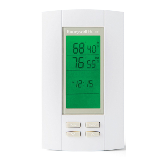
Page 5: Display Screen Reference
Display screen reference Wet: Indoor Window Frost: The control is humidity levels are protecting your home against too above 60% RH. much humidity based on outdoor Dry: Indoor humidity levels conditions. Humidity levels in your are below 20% relative home may not reach your desired humidity (RH.) RH% setting as a result. -
Page 6: Changing Humidifier Settings
Changing humidifier settings Note: These items will appear only if a humidifier is installed on your system. 1. Set humidifier by pressing UP/DOWN arrows. Tables below are recommended initial humidity settings based on outdoor temperature. If window frost setting (see next page) is not Humidify being used, the humidity setting should be adjusted manually when outdoor conditions change. - Page 7 MORE HUMIDITY LOOSE HOME/SINGLE-PANE WINDOWS TIGHT HOME/TRIPLE-PANE WINDOWS Humidify M24830 On the first cold day after TrueIAQ is installed, look for condensation M24832 ® on windows. If present, lower Frost Protection by one. Once set for your home, Frost Protection does not need to be changed again.
-
Page 8: Changing Dehumidifier Settings
Changing dehumidifier and ventilation settings Note: These items will appear only if a dehumidifier is installed. If both a humidifier and dehumidifier are installed, these settings will appear after pushing “More” from the humidifier operation style screen. 1. Set dehumidifier by pressing the UP/DOWN arrows. RH% will change in increments of five. -
Page 9: Changing Time Of Day
Changing time of day and service timers 1. Press “More.” Adjust hour using the the UP/DOWN arrows. 2. Press “More.” Adjust minutes using the UP/DOWN arrows. 3. Press “Done” to save settings. M24934 Service Timers 12 15 : Service timers appear when the humidifier, dehumidifier, ventilator, air filter, and/or UV bulbs need service. -
Page 10: Installation
Installation CAUTION: ELECTRICAL HAZARD. Can cause electrical shock or equipment damage. Disconnect power before beginning installation. 1. Turn system power off. 2. Choose a location. TrueIAQ can be mounted to a wall or directly to the return duct. ® M24787... - Page 11 Installation 3. Loosen the cover screw. 4. Separate the front housing from the base. M24814 5. For wall mounting, run wires through the back hole to the terminals. Wire size for all connectors: 2 x 18 AWG to 1 X 22 AWG. Install the mounting plate using two screws.
-
Page 12: Wiring
Wiring Pin description Pin capacity 24V supply. Must be common to G output. 24Vac±20% 1.5 amp max 24V supply common. 24Vac±20% Sensor Communication and supply bus to remote 24Vdc 64mA max sensors (sensor pins not polarized). Sensor Switch Override switch input. Active when R is 24Vac±20%, applied 10mA max in... - Page 13 Wiring Wiring TrueIAQ with a non-powered humidifier. ® OUTDOOR SENSOR HVAC TRANSFORMER – SENSOR TrueIAQ THERMOSTAT SENSOR SWITCH 12 15 HE100, HE200 VENT BYPASS HUMIDIFIER VENT DEHUM DEHUM M32534 69-2072—09...
- Page 14 Wiring Wiring TrueIAQ with a powered humidifier. ® OUTDOOR SENSOR SENSOR TrueIAQ SENSOR THERMOSTAT SWITCH 12 15 VENT HVAC HE150, HE250, VENT HE300, BYPASS DEHUM HUMIDIFIER DEHUM M32535 69-2072—09...
- Page 15 About your new thermostat Wiring Wiring TrueIAQ with OUTDOOR SENSOR ® TrueSTEAM. TrueIAQ SENSOR SENSOR HVAC 12 15 RECOMMENDED PRESSURE SWITCH FACTORY TrueSTEAM - INTERNAL INSTALLED JUMPER THERMOSTAT NOTE: IF PRESSURE SWITCH IS USED, ENSURE DIP 5 IS IN ON POSITION.
- Page 16 About your new thermostat Wiring Wiring TrueIAQ with a ® TH8110U R Rc dehumidifier and ventilation damper. TrueIAQ SENSOR OUTDOOR HVAC SENSOR 12 15 SENSOR (PROVIDED) SWITCH VENT EARD-6 VENT DEHUM DEHUM DH90 DEHUMIDIFIER GRAY DAMPER CONTROL (NOT USED) RED +24VAC POWER...
- Page 17 About your new thermostat Wiring Wiring TrueIAQ with a ® TH8110U humidifier and HRV/ERV R Rc ventilator. TrueIAQ SENSOR OUTDOOR HVAC SENSOR SENSOR 12 15 (PROVIDED) SWITCH ERV/HRV VENT VENT BLACK DEHUM GREEN DEHUM HE100 HE200 24 VOLT/40VA TRANSFORMER IF A THERMOSTAT OTHER THAN A TH5110, TH5220, TH5320, TH6110, TH6220, TH6320, TH8110, TH8320 OR TH8321 IS USED, A RELAY MAY BE REQUIRED TO ISOLATE THE G WIRE.
- Page 18 About your new thermostat Wiring Wiring TrueIAQ with a non- ® TH8110U R Rc powered humidifier, ventila- tion damper, and an auxiliary TrueIAQ exhaust fan. SENSOR OUTDOOR HVAC SENSOR 12 15 SENSOR (PROVIDED) SWITCH VENT EARD-6 VENT DEHUM DEHUM HE100...
-
Page 19: Mounting The Outdoor Sensor
Mounting the outdoor sensor 1. Do not mount on the south side of the house or in direct exposure to sunlight. 2. Keep at least 4 feet away from exhaust vents. 3. If in an air intake, place 1 foot closer to outside wall. - Page 20 Advanced HVAC installer setup instructions 1. Press and hold the UP/ 2. Press “More” to advance to the DOWN arrows for 3 seconds. next setup option. See table on next page. M24823 M24824 3. Use the UP/DOWN arrows to 4. Press “Done” at any time to save and select options.
- Page 21 About your new thermostat Advanced programming To be used by qualified HVAC technician. Setup functions Settings & Options (factory default in bold) Temperature Display 1=Fahrenheit; 2=Celcius Indoor Temperature Offset Set between -5 and 5 °F (-3 and 3 °C) to recalibrate tem- perature Outdoor Temperature Set between -5 and 5 °F (-3 and 3 °C) to recalibrate tem-...
-
Page 22: Advanced Programming
Advanced programming Setup functions Settings & Options (factory default in bold) Dehumidifier Operation 0=Dehum forces fan on 1=Dehum operates independent of fan Humidity Display Offset Set between -5% to 5% to recalibrate humidity sensing 0=OFF (no offset) Hum Service Timer 0,1,3,6,12 (months continuous) Hum Service Timer 0,1,3,6,12 (months intermittent) - Page 23 Advanced programming Setup functions Settings & Options (factory default in bold) Program Start Time 15 min increments (appears only if ISU125=1) 5:00 PM Program End Time 15 min increments (appears only if ISU125=1) 9:00 AM ASHRAE: # of Bedrooms 1-6 bedrooms; 2 ASHRAE: Home’s Sq Ft 10=1,000 Sq Ft;...
-
Page 24: Appendices Standards
7 minutes Mechanical Design • Vertical mount to cover one gang box Dimensions: 2-3/4” W x 4-3/4” H x 7/8” D • Flame Rating: UL94V-0 (TrueIAQ control); 2-3/4” W x 3-3/4” H x 7/8” • RoHS compliant D (Outdoor sensor) • Relay life: 100,000 cycles at 1A 24Vac Weight: .35 lbs (TrueIAQ control); .15 lbs (Outdoor sensor) Temperature Unit Display: °C/°F... -
Page 25: Warranty Information
This warranty does not cover removal or reinstallation costs. This warranty shall not apply if it is shown by Honeywell that the defect or malfunction was caused by damage which occurred while the product was in the possession of a consumer. - Page 26 69-2072—09...
- Page 27 69-2072—09...
- Page 28 Honeywell International Inc. 1985 Douglas Drive North Golden Valley, MN 55422 Honeywell Limited-Honeywell Limitée ® U.S. Registered Trademark. 35 Dynamic Drive © 2011 Honeywell International Inc. Toronto, Ontario M1V 4Z9 Patents pending. 69-2072—09 M.S. Rev. 03-11 http://yourhome.honeywell.com Printed in U.S.A.