
Related Manuals for Planet Networking & Communication WGSD-1022


Summary of Contents for Planet Networking & Communication WGSD-1022
- Page 1 User's Manual WGSD-1022 8-Port 10/100Mbps + 2-Port Gigabit TP/SFP Combo Managed Ethernet Switch...
-
Page 2: Fcc Warning
PLANET has made every effort to ensure that this User's Manual is accurate; PLANET disclaims liability for any inaccuracies or omissions that may have occurred. - Page 3 Revision PLANET 8-Port 10/100Mbps + 2 Gigabit TP/SFP combo Managed Ethernet Switch User's Manual FOR MODEL: WGSD-1022 REVISION: 1.2 (November.2007) Part No. 2081-A34030-002...
-
Page 4: Table Of Contents
TABLE OF CONTENTS 1. INTRODUCTION ..........................15 Packet Contents..........................15 How to Use This Manual........................15 Product Feature ..........................16 Product Specification ........................17 2. INSTALLATION ........................... 19 2.1 Product Description........................19 2.1.1 Product Overview ......................19 2.1.2 Switch Front Panel......................20 2.1.3 LED Indications........................ - Page 5 4.4.2 Port Config........................46 4.4.3 VLAN Group ........................47 4.4.4 GVRP Config ........................48 4.5. Spanning Tree........................... 50 4.5.1 STP Config ........................50 4.5.2 STP Port Config....................... 52 4.5.3 RSTP Port Config ......................54 4.5.4 MSTP Config ........................56 4.5.5 MSTP Instance Config ..................... 57 4.5.6 MSTP Interface Settings ....................
- Page 6 4.11.1 User Authentication ...................... 103 4.11.2 Dynamic Address ......................104 4.11.3 Mirroring........................105 4.11.4 Firmware Upgrade ....................... 106 4.11.5 Save Configuration ...................... 108 4.11.6 Warm Startup ....................... 110 4.11.7 Factory Default......................111 4.12 Statistics..........................112 4.12.1 RMON Statistic ......................112 4.12.2 EAP Statistic ........................
- Page 7 5.4.9 bridge aging-time ......................141 5.4.10 clear bridge ........................142 5.4.11 port security ......................... 143 5.4.12 port security routed secure-address ................143 5.4.13 show bridge address-table................... 144 5.4.14 show bridge address-table static ................. 145 5.4.15 show bridge address-table count ................. 146 5.4.16 show bridge multicast address-table................
- Page 8 5.7.7 negotiation ........................172 5.7.8 flowcontrol........................172 5.7.9 mdix ..........................173 5.7.10 back-pressure ......................174 5.7.11 port jumbo-frame......................175 5.7.12 clear counters ......................175 5.7.13 set interface active....................... 176 5.7.14 show interfaces configuration ..................176 5.7.15 show interfaces status ....................178 5.7.16 show interfaces description..................
- Page 9 5.10.3 ip default-gateway......................201 5.10.4 show ip interface......................202 5.10.5 arp ..........................202 5.10.6 arp timeout........................203 5.10.7 clear arp-cache ......................204 5.10.8 show arp ........................204 5.11 LACP Commands ........................205 5.11.1 lacp system-priority ...................... 205 5.11.2 lacp port-priority ......................205 5.11.3 lacp timeout........................
- Page 10 5.17.1 qos..........................226 5.17.2 show qos........................226 5.17.3 wrr-queue cos-map...................... 227 5.17.4 wrr-queue bandwidth ....................228 5.17.5 priority-queue out num-of-queues................229 5.17.6 show qos interface....................... 230 5.17.7 qos map dscp-queue ....................233 5.17.8 qos trust (Global) ......................233 5.17.9 qos trust (Interface)...................... 234 5.17.10 qos cos ........................
- Page 11 5.20.6 snmp-server host ......................262 5.20.7 snmp-server set ......................263 5.20.8 show snmp........................264 5.21 Spanning-Tree Commands ....................266 5.21.1 spanning-tree....................... 266 5.21.2 spanning-tree mode ..................... 266 5.21.3 spanning-tree forward-time ..................267 5.21.4 spanning-tree hello-time ....................267 5.21.5 spanning-tree max-age ....................268 5.21.6 spanning-tree priority ....................
- Page 12 5.23.7 show users........................293 5.23.8 show sessions ......................294 5.23.9 show system ........................ 294 5.23.10 show version......................296 5.24 Syslog Commands......................... 296 5.24.1 logging on ........................296 5.24.2 logging ......................... 297 5.24.3 logging console......................298 5.24.4 logging buffered ......................299 5.24.5 logging buffered size....................
- Page 13 5.27.3 default-vlan disable...................... 317 5.27.4 interface vlan ....................... 318 5.27.5 interface range vlan ..................... 319 5.27.6 name..........................319 5.27.7 switchport mode......................320 5.27.8 switchport access vlan ....................321 5.27.9 switchport trunk allowed vlan ..................321 5.27.10 switchport trunk native vlan..................322 5.27.11 switchport general allowed vlan .................
- Page 14 5.29.11 dot1x timeout server-timeout..................342 5.29.12 show dot1x......................... 343 5.29.13 show dot1x users....................... 345 5.29.14 show dot1x statistics ....................346 5.29.15 dot1x auth-not-req ..................... 348 5.29.16 dot1x multiple-hosts ....................348 5.29.17 dot1x single-host-violation ..................349 5.29.18 show dot1x advanced ....................350 TROUBLE SHOOTING .........................
-
Page 15: Introduction
The section contains specifications of the Switch. • Appendex A The section contains cable information of the Switch. In the following section, terms "Switch" with upper case denotes the WGSD-1022 Managed Ethernet switch. Terms with lower case "switch" means other Ethernet switch devices. -
Page 16: Product Feature
Product Feature Generic Features Comply with the IEEE 802.3, IEEE 802.3u, IEEE 802.3ab, IEEE 802.3z Gigabit Ethernet standard 8-Port 10/100Mbps TP interfaces with auto-negotiation. 2 10/100/1000Mbps TP ports and 2 SFP shared combo interfaces Supports auto-negotiation and Half-Duplex / Full-Duplex modes for all 10Base-T/100Base-TX and 1000Base-T ports. -
Page 17: Product Specification
Virtual Cable Test (VCT) technology provides the mechanism to detect and report potential cabling issues, such as cable opens, cable shorts, etc. on Copper Links EMI standards comply with FCC, CE class A,WEEE RoHS Product Specification WGSD-1022 Product 8-Port 10/100Mbps + 2 Gigabit TP / SFP combo Managed Ethernet Switch Hardware Specification... - Page 18 IP Packet IGMP Snooping Allow to disable or enable. Standards Conformance Regulation Compliance FCC Part 15 Class A, CE IEEE 802.3 10BASE-T IEEE 802.3u 100BASE-TX/100BASE-FX IEEE 802.3z Gigabit SX/LX IEEE 802.3ab Gigabit 1000T IEEE 802.3x Flow Control and Back pressure Standards Compliance IEEE 802.3ad Port trunk with LACP IEEE 802.1d Spanning tree protocol...
-
Page 19: Installation
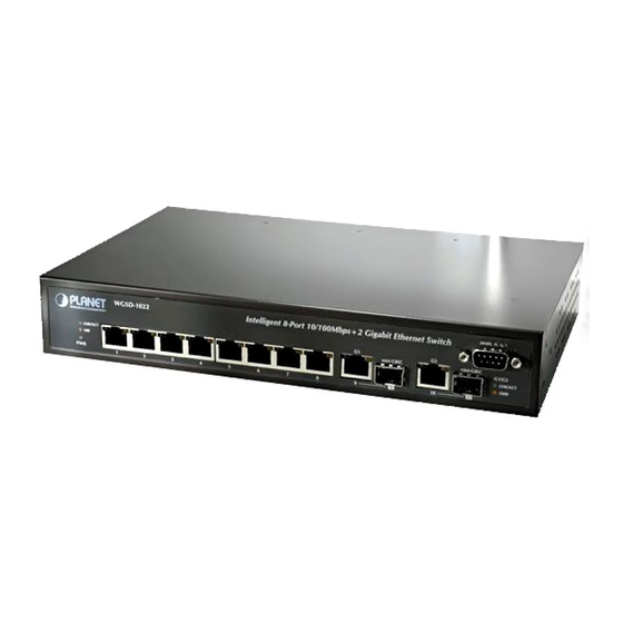
2.1 Product Description The PLANET WGSD-1022 is a 8-Port 10/100Mbps with 2 shared SFP/copper GbE interfaces Gigabit Ethernet Switch. It boasts a high performance switch architecture that is capable of providing non-blocking switch fabric and wire-speed throughput as high as 5.6Gbps. Its two built-in GbE uplink ports also offer incredible extensibility, flexibility and connectivity to the Core switch or Servers. -
Page 20: Switch Front Panel
38400, N, 8, 1 Intelligent 8-Port 10/100Mbps+2 Gigabit Ethernet Switch LNK/ACT mini-GBIC mini-GBIC G1/G2 LNK/ACT 1000 Figure 2-1 WGSD-1022 front panel. 2.1.3 LED Indications System Color Function Green Lights to indicate that the Switch has power. Per 10/100Mbps port Color Function Lights to indicate the link through that port is successfully established. -
Page 21: Install The Switch
Power Notice: The device is a power-required device, it means, it will not work till it is powered. If your networks should active all the time, please consider using UPS (Uninterrupted Power Supply) for your device. It will prevent you from network data loss or network downtime. In some area, installing a surge suppression device may also help to protect your switch from being damaged by unregulated surge or current to the Switch or the power adapter. -
Page 22: Rack Mounting
2.2.2 Rack Mounting To install the Switch in a 19-inch standard rack, please follows the instructions described below. Step1: Place the Switch on a hard flat surface, with the front panel positioned towards the front side. Step2: Attach the rack-mount bracket to each side of the Switch with supplied screws attached to the package. -
Page 23: Installing The Sfp Transceiver
Figure 2-7 Plug-in the SFP transceiver Approved PLANET SFP Transceivers PLANET WGSD-1022 support both single mode and multi mode SFP transceiver. The following list of approved PLANET SFP transceivers is correct at the time of publication: ■MGB-SX SFP (1000BASE-SX SFP transceiver ) ■MGB-LX SFP (1000BASE-LX SFP transceiver ) - Page 24 Connect the fiber cable Attach the duplex LC connector on the network cable into the SFP transceiver. Connect the other end of the cable to a device – switches with SFP installed, fiber NIC on a workstation or a Media Converter.. Check the LNK/ACT LED of the SFP slot on the front of the Switch.
-
Page 25: Configuration
3. CONFIGURATION This chapter explains the methods that you can use to configure management access to the Switch. It describes the types of management applications and the communication and management protocols that deliver data between your management device (work-station or personal computer) and the system. It also contains information about port connection options. -
Page 26: Administration Console
‧Most visually appealing ‧May encounter lag times on poor connections ‧Communicates with switch functions at ‧Requires SNMP manager software SNMP ‧Least visually appealing of all three Agent the MIB level ‧Based on open standards methods ‧Some settings require calculations ‧Security can be compromised (hackers need only know the community name) Table 3-1 Management Methods Comparison... -
Page 27: Web Management
You can change these settings, if desired, after you log on. This management method is often preferred because you can remain connected and monitor the system during system reboots. Also, certain error messages are sent to the serial port, regardless of the interface through which the associated action was initiated. -
Page 28: Snmp Protocol
3.4.2 SNMP Protocol Simple Network Management Protocol (SNMP) is the standard management protocol for multi-vendor IP networks. SNMP supports transaction-based queries that allow the protocol to format messages and to transmit information between reporting devices and data-collection programs. SNMP runs on top of the User Datagram Protocol (UDP), offering a connectionless-mode service. -
Page 29: Web Configuration
4. Web Configuration The WGSD-1022 can be configured through an Ethernet connection, make sure the manager PC must be set on same the IP subnet address with the Switch. For example, if you have changed the default IP address of the Switch to 192.168.1.1 with subnet mask 255.255.255.0 via console, then the manager PC should be set at 192.168.1.x (where x is a number between 1 and 253) with subnet mask 255.255.255.0. - Page 30 Figure 4-3 Web Main Screen of WGSD-1022 Now, you can use the Web management interface to continue the Switch management or manage the Switch by console interface. Note: It is recommended to use Internet Explore 6.0 or above to access WGSD-1022.
-
Page 31: Main Screen
Sub Menu Main Screen Figure 4-1 Via the Web-Management, the administrator can setup the WGSD-1022 by select the functions those listed in the Main Function. The screen in Figure 4-2 appears. Figure 4-2 WGSD-1022 Main Funcrions Menu The following functions can be configured here:... -
Page 32: System
4.2 System The Setup menus include the tree sub-menus: Information IP Config SNTP 4.2.1 Information The Information screen provides Device and System Information of the Switch. Figure 4-3 System Information screen The page contains the following informations: The product name of this Switch •... -
Page 33: Ip Config
4.2.2 IP Config The Basic Setup Table include the IP Config (see figure 4-4), which allows you to assign DHCP or static IP settings to interfaces and assign default gateways. In the IP Config screen, you can set these parts as below: Figure 4-4 IP Config screen The page includes the following fields:... -
Page 34: Sntp
• Gateway Enter the default gateway for the IP interface. The factory default value is 0.0.0.0 • DNS Server Enter the IP Address of the DNS Server. The Domain Name System (DNS) converts user-defined domain names into IP addresses 4.2.3 SNTP In the Basic Setup Table, you can see the SNTP (see figure 4-5), by which you can configure the time settings for the Switch. - Page 35 • Time Zone The difference between Greenwich Mean Time (GMT) and local time. For example, the Time Zone Offset for Paris is GMT +1, while the local time in Taipei is GTM +8 Enables the Daylight Savings Time (DST) on the device based on the •...
- Page 36 The possible field range is Sunday-Saturday. • Week -- The week within the month from which DST begins every year. The possible field range is 1-5. • Month -- The month of the year in which DST begins every year. The possible field range is Jan.-Dec.
-
Page 37: Port Configuration
4.3 Port Configuration In this field, you can see these parts, such as Port settings, Link aggregation, LACP Config. 4.3.1 Port Settings To use the port settings screen for setting up each of the Switch’s ports. It shows these parts: port#, memo, admin control, link status, current speed, duplex mode, MDI/MDIX, Flow control, Phy type, LAG, PVE (see Figure 4-6): Figure 4-6 Port Settings screen... - Page 38 configured only when auto-negotiation is disabled on that port • Duplex Mode The port duplex mode, Full (transmission occurs in both directions simultaneously) or Half (transmission occurs in only one direction at a time). This mode can be configured only when auto-negotiation is disabled and port speed is set to 10Mbps or 100Mbps.
- Page 39 Edit Click the button for more detail port configuration. Port Configuration Detail screen (see figure 4-7) Figure 4-7 Per Port Configuration detail screen The Port Configuration screen contains the following fields: • Port Indicates the number of the port • Memo Where can be entered by clicking on the Detail button •...
- Page 40 • Current Port Speed The current speed of the port is displayed here • Auto Negotiation You can enable or disable the port’s Auto Negotiation feature. If using an SFP module, Auto Negotiation for the specific port should be set to disable •...
-
Page 41: Link Aggregation
4.3.2 Link Aggregation When you enter the Link Aggregation, you can see these parts (see figure 4-8), such as: LAG, shows whether the port is part of a LAG. Figure 4-8 Link Aggregation screen The Link Aggregation page contains the following fields: •... - Page 42 uses Full Duplex Mode • LAG Status Shows the current mode of the LAG interface • Edit It will open the port configuration detail screen Edit Click the button for more detail port configuration. Link Aggregation detail configuration At per-LAG detail configuration page, the administrator can select ports to be the members of the LAG interface.
-
Page 43: Lacp Config
4.3.3 LACP Config Aggregated Links can be manually setup or automatically established on the relevant links by enabling Link Aggregation Control Protocol (LACP). Aggregate ports can be linked into link-aggregation port-groups. Each group is comprised of ports with the same speed, set to full-duplex operation. The LACP screen contains fields for configuring LACP LAG s (see figure 4-10) Figure 4-10 LACP configuration screen The page contains the following fields:... -
Page 44: Vlan Configuration
Layer 2 switch. However, all the network devices are still plug into the same switch physically. The WGSD-1022 supports 802.1Q (tagged-based) and GVRP Dynamic VLAN setting in web management page. In the default configuration, VLAN support is “802.1Q”. -
Page 45: Create Vlan
4.4.1 Create VLAN In this table, the information and global parameters for configuring and working with VLAN s will be provided (see figure 4-11). Figure 4-11 Create VLAN screen The page contains the following fields: Single VLAN You can configure the ID number of the VLAN by this item. Up to 256 •... -
Page 46: Port Config
4.4.2 Port Config In this port setting screen (refer to figure 4-12), the parameters managing ports that are part of a VLAN will be provided, and you can set the default VLAN ID (PVID). All untagged packets arriving to the device are tagged by the ports PVID. -
Page 47: Vlan Group
• Ingress Filtering Enables or disables Ingress filtering on the port. Ingress filtering discards packets which do not include an ingress port • LAG Indicates the LAG to which the VLAN is defined Port Mode VLAN Membership Frame Leave Untagged Access Belongs to a single untagged VLAN ( Tag=PVID be removed) -
Page 48: Gvrp Config
The page contains the following fields: • VLAN Where means the VLAN number • Access Indicates the port belongs to a single untagged VLAN. When a port is in Access mode, the packet types which are accepted on the port cannot be designated. - Page 49 Figure 4-14 GVRP configuration screen The page contains the following fields: • Set GVRP Enables and disables GVRP on the device Displays the interface on which GVRP is enabled. Possible field • Port# values are: Port - indicates the port number on which GVRP is enabled. LAG - indicates the LAG number on which GVRP is enabled.
-
Page 50: Spanning Tree
4.5. Spanning Tree Spanning Tree Protocol (STP) provides tree topography for any arrangement of bridges. STP also provides one path between end stations on a network, eliminating loops. Loops occur when alternate routes exist between hosts. Loops in an extended network can cause bridges to forward traffic indefinitely, resulting in increased traffic and reducing network efficiency. - Page 51 The page contains the following fields: • STP Mode This indicates the STP mode by which STP is enabled on the device. The possible field values are: • Classic STP, where enables Classic STP on the device. This is the default value.
-
Page 52: Stp Port Config
4.5.2 STP Port Config Network administrators can assign STP Port Config to specific interfaces using the STP Interface Settings screen (see figure 4-16). The STP Interface Settings page contains the following fields: Figure 4-16 STP Port Config screen The page contains the following fields: •... - Page 53 • Forwarding, the port that can forward traffic and learn new MAC addresses. • Speed Indicates the speed at which the port is operating • Path Cost Indicates the port contribution to the root path cost. The path cost is adjusted to a higher or lower value, and is used to forward traffic when a path being rerouted.
-
Page 54: Rstp Port Config
STP Port status table Figure 4-17 STP Port status screen 4.5.3 RSTP Port Config While the classic spanning tree prevents Layer 2 forwarding loops in a general network topology, convergence can take between 30-60 seconds. This time may delay detecting possible loops, and propagating status topology changes. - Page 55 Figure 4-18 RSTP Port Settings screen The page contains the following fields: • Port# Where displays the port or LAG on which Rapid STP is enabled. • Role Where indicates the port role assigned by the STP algorithm in order to provide to STP paths.
-
Page 56: Mstp Config
To establish communications over a point-to-point link, the originating PPP first sends Link Control Protocol (LCP) packets to configure and test the data link. After a Note link is established and optional facilities are negotiated as needed by the LCP, the originating PPP sends Network Control Protocols (NCP) packets to select and configure one or more network layer protocols. -
Page 57: Mstp Instance Config
The page contains the following fields: • Region Name Where provides a user-defined STP region name • Revision Where defines unsigned 16-bit number that identifies the revision of the current MST configuration. The revision number is required as part of the MST configuration. The possible field range 0-65535. - Page 58 The page contains the following fields: • Instance ID Defines the VLAN group to which the interface is assigned. • Included VLAN Where maps the selected VLAN to the selected instance. Each VLAN belongs to one instance. • Bridge Priority Specifies the selected spanning tree instance device priority.
-
Page 59: Mstp Interface Settings
4.5.6 MSTP Interface Settings Network Administrators can assign MSTP Interface settings using the MSTP Interface Settings screen (see figure 4-22). Figure 4-22 MSTP Interfance Settings screen The MSTP Interface Settings screen contains the following fields: • Instance ID# Lists the MSTP instances configured on the device. Possible field range is 0-15. - Page 60 the outlying CIST root. • Internal, indicates the port is an internal port. • Role Indicates the port role assigned by the STP algorithm in order to provide to STP paths. The possible field values are: • Root, provides the lowest cost path to forward packets to root device.
- Page 61 Figure 4-23 MSTP Interfance configuration screen...
-
Page 62: Multicast
4.6 Multicast The Multicast of the Switch On this field: included IGMP Snooping and Bridge Multicast. 4.6.1 IGMP Snooping When IGMP Snooping (see figure 4-24) is enabled globally, all IGMP packets are forwarded to the CPU. The CPU analyzes the incoming packets and determines which ports want to join which Multicast groups, which ports have Multicast routers generating IGMP queries, which routing protocols are forwarding packets and Multicast traffic. -
Page 63: Bridge Multicast
• VLAN ID Specifies the VLAN ID. • IGMP Status Indicates if IGMP snooping is enabled on the VLAN. • Auto Learn Indicates if Auto Learn is enabled on the device. If Auto Learn is enabled, the device automatically learns where other Multicast groups are located. - Page 64 Figure 4-25 Bridge Multicast screen The Page contains the following fields: • Set Bridge Multicast The check box allows enable Bridge Multicast Filtering function. Filtering This identifies a VLAN to be configured to a Multicast service. • VLAN ID Identifies the Multicast group MAC address/IP address. •...
- Page 65 Multicast Table Figure 4-26 Bridge Multicast screen Example: Adding Bridge Multicast Addresses Click the check box to enable the Bridge Multicast Filtering. Define the VLAN ID and New Bridge Multicast Address fields. Check a port to Static to join the port to the selected Multicast group. Click “Add to Table”...
-
Page 66: Qos
4.7 QoS Network traffic is usually unpredictable, and the only basic assurance that can be offered is best effort traffic delivery. To overcome this challenge, Quality of Service (QoS) is applied throughout the network. This ensures that network traffic is prioritized according to specified criteria, and that specific traffic receives preferential treatment. -
Page 67: Settings
• 6.67% Bandwidth • 13.33% • 26.67% • 53.33% 4.7.2 802.1p Settings The terms Class of Service (CoS) and QoS are used in the following: CoS provides varying Layer 2 traffic services. CoS refers to classification of traffic to traffic-classes, which are handled as an aggregate whole, with no per-flow settings. - Page 68 The Page contains the following fields: This indicates if QoS is enabled on the interface. The possible values • Select QoS Mode are: • Disable, disables QoS on the interface. • Port Qos, enables QoS on the interface. • Policy Qos, enables the Advanced Mode QoS on the interface. •...
-
Page 69: Dscp Settings
4.7.3 DSCP Settings The DSCP Settings screen (see figure 4-29) enables mapping DSCP values to specific queues Figure 4-29 DSCP Settings screen The DSCP Settings screen contains the following fields: Indicates the Differentiated Services Code Point value in the incoming •... -
Page 70: Rate Limit
4.7.4 Rate Limit The Bandwidth screen (refer to figure 4-30) allows network managers to define the bandwidth settings for a specified egress interface. Modifying queue scheduling affects the queue settings globally. The Bandwidth screen is not used with the Service mode, as bandwidth settings are based on services. Figure 4-30 Rate limit screen Queue shaping can be based per queue and/or per interface. -
Page 71: Port Qos
Rate on Selected Port • Committed Defines CIR as the queue shaping type. Information Rate The possible field value is 64 - 1,000,000 Kbps. (CIR) 4.7.5 Port Qos The Port Qos screen (see figure 4-31) contains the following fields: Figure 4-31 Port Qos screen The page contains the following fields: •... -
Page 72: Policy Qos
4.7.6 Policy Qos Policy Qos (see figure 4-32) provides rules for specifying flow classification and assigning rule actions that relate to bandwidth management. The rules are based on the Access Control Lists (see Access Control Tab) Figure 4-32 Policy Qos screen MAC ACLs and IP ACLs can be grouped together in more complex structures, called policies. - Page 73 Figure 4-33 Out of Profile DSCP Assignments screen The page contains the following fields: This displays the DSCP In value. • DSCP In The value is form 0-63. • DSCP Out This displays the current DSCP out value. A new value can be selected from the pull-down menu The Policy Settings button opens the Policy Name screen (see figure 4-34):...
- Page 74 Figure 4-34 Policy Settings screen The page contains the following fields: defines a new Policy name • Policy Name • Add to List this button will add the policy to the Policy Name table • Select Policy which selects an existing Policy by name •...
- Page 75 Class Map setting New Class Map, by which the New Class Map button opens the New Class Map screen (see figure 4-35) Figure 4-35 Class Map Settings screen The page contains the following fields: • Class Map Name defines a new Class Map name •...
- Page 76 • MAC Based ACLs, matches packets to MAC based ACLs first, then matches packets to IP based ACLs. • IP ACL Matches packets to IP based ACLs first, and then matches packets to MAC based ACLs. • Match Criteria used to match IP addresses and /or MAC addresses with an ACL’s address.
- Page 77 The page contains the following fields: • Aggregate Policer Where enter a name in this field. Name • Ingress Committed This defines the CIR in bits per second. This field is only relevant when the Police value is Single. Information Rate (CIR) •...
-
Page 78: Access Control
4.8 Access Control An ACL consists of a set of rules which are matched sequentially against a packet. When a packet meets the match criteria of a rule, the specified rule action (Permit/Deny) is taken and the additional rules are not checked for a match. - Page 79 follows: • Permit, by which forwards packets which meet the ACL criteria. • Deny, which drops packets which meet the ACL criteria. • Shutdown, where drops packet that meets the ACL criteria, and disables the port to which the packet was addressed. Ports are reactivated from the Port Management screen.
- Page 80 • Rst, indicates the connection is dropped. • Syn, indicates request to start a session. • Fin, indicates request to close a session. • Source Port Defines the TCP/UDP source port to which the ACE is matched. This field is active only if 800/6-TCP or 800/17-UDP is selected in the Select from List drop-down menu.
-
Page 81: Layer2 Based Acl
4.8.2 Layer2 Based ACL The Layer2 Based ACL screen (see figure 4-38) allows a MAC based ACL to be defined. ACEs can be added only if the ACL is not bound to an interface. Figure 4-38 Layer2-Base ACL screen The Page contains the following fields: •... - Page 82 important. A wildcard of 0.0.0.0 indicates that all the bits are important. For example, if the source IP address 149.36.184.198 and the wildcard mask is 255.36.184.00, the first eight bits of the IP address are ignored, while the last eight bits are used. •...
-
Page 83: Security
4.9 Security This section is to control the security access of the switch, includes the user access and management control. The Security function contains links to the following topics: • ACL Binding • RADIUS • TACACS+ • 802.1x Settings • Port Security •... -
Page 84: Radius Config
• Port, indicates port to apply the ACL • LAG, indicates LAG to apply the ACL • ACL Name Indicates the ACL which is bound to the interface. The selection includes: • Layer3 Based ACL • Layer2 Based ACL Add to Table Use the button to add the ACL Binding configuration to the ACL Binding Table at the bottom of the screen. - Page 85 The authenticated port default is 1812 • Number of Retries Defines the number of transmitted requests sent to RADIUS server before a failure occurs. The possible field values are 1 - 10. Three is the default value. • Timeout for Reply This defines the amount of the time in seconds the device waits for an answer from the RADIUS server before retrying the query, or switching to the next server.
-
Page 86: Tacacs+ Config
4.9.3 TACACS+ Config The device provides Terminal Access Controller Access Control System (TACACS+) client support. TACACS+ provides centralized security for validation of users accessing the device. TACACS+ provides a centralized user management system, while still retaining consistency with RADIUS and other authentication processes. - Page 87 between the device and the TACACS+ server times out. Reply The field range is 1-30 seconds. • Status Displays the connection status between the device and the TACACS+ server. The possible field values are: • Connected, there is currently a connection between the device and the TACACS+ server.
-
Page 88: Settings
4.9.4 802.1x settings Port based authentication enables authenticating system users on a per-port basis via an external server. Only authenticated and approved system users can transmit and receive data. Ports are authenticated via the RADIUS server using the Extensible Authentication Protocol (EAP). Refer to figure 4-42. -
Page 89: Port Security
4.9.5 Port Security Work security screen (see figure 4-43) can be increased by limiting access on a specific port only to users with specific MAC addresses. MAC addresses can be dynamically learned or statically configured. Locked port security monitors both received and learned packets that are received on specific ports. - Page 90 Disabled ports are activated from the Port Security page. • Port# Where displays the port or LAG name • Lock Interface Which selecting this option locks the specified interface. • Learning Mode Where defines the locked port type. The Learning Mode field is enabled only if Locked is selected in the Interface Status field.
-
Page 91: Multiple Hosts
4.9.6 Multiple Hosts The Multiple Hosts screen (see figure 4-44) allows network managers to configure advanced port-based authentication settings for specific ports and VLANs. Figure 4-44 Multiple Hosts screen The Page contains the following fields: • Port# Displays the port number for which advanced port-based authentication is enabled. -
Page 92: Storm Control
Frequency (1-1000000) field can be defined only if multiple hosts are disabled. The default is 10 seconds. • Status Where indicates the host status. 4.9.7 Storm control A BroadcastStorm is a result of an excessive amount of broadcast messages simultaneously transmitted across a network by a single port. -
Page 93: Snmp
• Multicast & Broadcast, counts Broadcast and Multicast traffic together. • Broadcast Only, counts only Broadcast traffic. • Rate Threshold Where the maximum rate (packets per second) at which unknown packets are forwarded. The range is 70 -100000. The default value is 3500. 4.10 SNMP Simple Network Management Protocol (SNMP) provides a method for managing network devices. - Page 94 The Global Parameter Screen contains the following fields: • Local Engine ID Indicates the local device engine ID. The field value is a hexadecimal string. Each byte in hexadecimal character strings consists of two hexadecimal digits. Each byte can be separated by a period or a colon.
-
Page 95: Group Profile
4.10.2 Group Profile The Group Profile screen (see figure 4-47) provides information for creating SNMP groups and assigning SNMP access control privileges to SNMP groups. Groups allow network managers to assign access rights to specific device features, or features aspects. Figure 4-47 Group Profile screen The page contains the following fields: •... -
Page 96: Group Membership
• Operation Defines the group access rights. The possible field values are: • Read. The management access is restricted to read-only, and changes cannot be made to the assigned SNMP view. • Write. The management access is read-write and changes can be made to the assigned SNMP view. - Page 97 • Authentication Indicates the Authentication method used. The possible field values are: Method • None, that no authentication method is used to authenticate the port. • MD5 Password, that port authentication is performed via HMAC-MD5-96 password authentication. • SHA Password, that port authentication is performed via HMAC-SHA-96 password authentication.
-
Page 98: Communities
4.10.4 Communities The Communities screen contains three areas: • Communities • Basic Table • Advanced Table The screens in Figure 4-49 and 4-50 sppears Communities Figure 4-49 Communities configuration screen The page contains the following fields: • SNMP Management Defines the management station IP address for which the advanced SNMP community is defined. - Page 99 possible field values are: • Read Only - which indicates management access is restricted to read-only, and changes cannot be made to the community. • Read Write - management access is read-write and changes can be made to the device configuration, but not to the community.
-
Page 100: Notification Recipient
The page contains the following fields: • Management Station Displays the management station IP address for which the basic SNMP community is defined. • Community String Displays the password used to authenticate the management station to the device. • Access Mode Where displays the access rights of the community. - Page 101 The page contains the following fields: • Recipient IP Which indicates the IP address to whom the traps are sent. • Notification Type Defines the notification sent. The possible field values are: Traps, indicates traps are sent. Informs, indicates informs are sent. •...
-
Page 102: Manage
Use the Add to Table button when you want to add the Notification Recipient configuration to the relevant table at the bottom of the screen. Figure 4-52 Notification Recipient 4.11 Manage The Manage section provides information for devining system parameters including User account and file management, device software. -
Page 103: User Authentication
4.11.1 User Authentication The User Authentication screen (see figure 4-53) is used to modify user passwords. Figure 4-53 User Authentication screen The page contains the following fields: • Authentication Type Defines the user authentication methods. Also you can choose combinations of all the authentication methods. The possible field values are: •... -
Page 104: Dynamic Address
4.11.2 Dynamic Address The Dynamic Address Table contains the MAC addresses learned by monitoring the source address for traffic entering the switch. When the destination address for inbound traffic is found in the database, the packets intended for that address are forwarded directly to the associated port. Otherwise, the traffic is flooded to all ports. -
Page 105: Mirroring
interface types from which to select: • Port - displays the specific port number • LAG - displays the specific LAG number. • MAC Address Specifies the MAC address for which the table is queried • VLAN ID Specifies the VLAN ID for which the table is queried. 4.11.3 Mirroring Port mirroring monitors and mirrors network traffic by forwarding copies of incoming and outgoing packets from one port to a monitoring port. -
Page 106: Firmware Upgrade
The page contains the following fields: • Mirrored Port Defines the port to which traffic is mirrored. • Type Indicates the port mode configuration for port mirroring. The possible field values are: • RxOnly, defines the port mirroring on receiving ports. This is the default value. - Page 107 The page contains the following fields: Via TFTP • Via TFTP Defines the upgrade through a TFTP Server. • File Type Select file type to be upgraded through a TFTP Server. The possible field values are : • Software Image •...
-
Page 108: Save Configuration
4.11.5 Save Configuration On this screen, you can choose two methods to save the configuration: Via TFTP Upgrade and Via HTTP. See figure 4-58 Figure 4-58 Save Configuration via TFTP The page contains the following fields: Via TFTP • Via TFTP Upgrade Select this option to upgrade the switch from a file located on a TFTP Server. - Page 109 Via HTTP This HTTP Firmware Upgrade screen is used for saving configuration information using your Web browser. See figure 4-59 Figure 4-59 Save Configuration via HTTP • Upgrade Select this option to upgrade the switch from a file on the local hard drive.
-
Page 110: Warm Startup
4.11.6 Warm Startup The Reboot screen (see figure 4-60) resets the device whose configuration is automatically saved before the device is rebooted. Figure 4-60 Warm startup screen There is a known issue. Sometimes after the “Reboot” button be pressed, it costs lot Note time to stop the curent tasks. -
Page 111: Factory Default
4.11.7 Factory Default The Factory Reset screen (see figure 4-61) allows network managers to reset the device to the factory defaults settings, but if you restore factory defaults results in erasing the configuration file. Although restoring the factory defaults will erase your configuration, you can save a backup of your current configuration settings from the Admin - Save Configuration screen. -
Page 112: Statistics
4.12 Statistics The Statistic of the Switch This field includes these parts as below: 4.12.1 RMON Statistic The RMON Statistics screen (refer to figure 4-62) contains fields for viewing information about device utilization and errors that occurred on the device. Figure 4-62 RMON Statistics screen The page contains the following fields: •... - Page 113 every 60 seconds. • Drop Events which displays the number of dropped events that have occurred on the interface since the device was last refreshed • Received Bytes Displays the number of octets received on the interface since the device was last refreshed. This number includes bad packets and (Octets) FCS octets, but excludes framing bits •...
-
Page 114: Eap Statistic
4.12.2 EAP Statistic The EAP Statistic screen (see figure 4-63) contains information about EAP packets received on a specific port. Figure 4-63 EAP Statistics screen The page includes the following fields: • Port Indicates the port, which is polled for statistics •... -
Page 115: Gvrp Statistics
4.12.3 GVRP Statistics The GVRP Statistics screen (see figure 4-64) contains device statistics for GVRP. The GVRP Statistics screen is divided into two areas, GVRP Statistics Table and GVRP Error Statistics Table. Figure 4-64 GVRP Statistics screen The following fields are relevant for both tables: Specifies the interface type for which the statistics are displayed •... - Page 116 • Join Empty Which displays the device GVRP Join Empty statistics • Empty Displays the device GVRP Empty statistics • Leave Empty By which displays the device GVRP Leave Empty statistics • Join In By which displays the device GVRP Join In statistics •...
-
Page 117: Command Structure
5. COMMAND STRUCTURE The WGSD-1022 is a managed Ethernet Switch that can be controlled by the RS-232 console interface, telnet interface, and Web interface. This chapter describer how to configure the Switch through these interfaces. When you are ready to configure the smart functions of the Switch, make sure you had connected the supplied RS-232 serial cable to the RS-232 port at the front panel of your WGSW-24010 Switch and your 5.1 Connect to PC’s RS-232 serial port... -
Page 118: Using The Cli
5.2 Using the CLI 5.2.1 CLI Command Modes The Command Line Interface (CLI) syntax, conventions and terminology are described in this section. Each CLI command is illustrated using the structure outlined below. Introduction To assist in configuring devices, the CLI command-line interface is divided into different command modes. Each command mode has its own set of specific commands. -
Page 119: Global Configuration Mode
Privileged users are entered directly into the Privileged EXEC mode. To enter the Privileged EXEC mode commands from the User EXEC mode perform the following: At the prompt enter the command enable and press <Enter>. A password prompt is displayed. Enter the password and press <Enter>. The password is displayed as "*". - Page 120 exit Ctrl+Z The following example illustrates how to access Global Configuration mode and teturn back to the Privileged EXEC mode: console # console # configure console(config) # exit console # Interface Configuration Mode and Specific Configuration Modes Interface Configuration commands are to modify specific interface operations. The following are the Interface Configuration modes: Line Interface—Contains commands to configure the management connections.
-
Page 121: Starting The Cli
SSH Public Key-chain Configuration mode. MAC Access-List—Configures conditions required to allow traffic based on MAC addresses. The Global Configuration mode command mac-access list is used to enter the MAC access-list configuration mode. Interface—Contains commands that configure the interface. The Global Configuration mode command interface ethernet is used to enter the interface configuration mode. -
Page 122: Editing Features
5.2.3 Editing Features Entering Commands A CLI command is a series of keywords and arguments. Keywords identify a command, and arguments specify configuration parameters. For example, in the command "show interfaces status ethernet e5," show, interfaces and status are keywords, ethernet is an argument that specifies the interface type, and e5 specifies the port. -
Page 123: Negating The Effect Of Commands
Keyword Source or destination Up-arrow key Recalls commands in the history buffer, beginning with the most recent command. Ctrl+P Repeats the key sequence to recall successively older commands. Down-arrow Returns to more recent commands in the history buffer after recalling commands with the up-arrow key. -
Page 124: Keyboard Shortcuts
Keyboard Shortcuts The CLI has a range of keyboard shortcuts to assist in editing the CLI commands. The following table describes the CLI shortcuts. Keyboard Key Description Up-arrow key Recalls commands in the history buffer, beginning with the most recent command. -
Page 125: Aaa Commands
Ctrl+F4 Any combination keys pressed simultaneously on the keyboard. Screen Indicates system messages and prompts appearing on the console. Display When a parameter is required to define a range of ports or parameters and all is an option, the default for the command is all when no parameters are defined. For example, the command interface range port-channel has the option of either entering a range of channels, or selecting all. -
Page 126: Aaa Authentication Enable
Default Configuration The local user database is checked. This has the same effect as the command aaa authentication login listname local. Note: On the console, login succeeds without any authentication check if the authentication method is not defined. Command Mode Global Configuration mode User Guidelines The default and optional list names created with the aaa authentication login command are used with... -
Page 127: Default Configuration
Keyword Source or destination Enable Uses the enable password for authentication. Line Uses the line password for authentication None Uses no authentication Radius Uses the list of all radius servers for authentication. Uses username “$enabx$.” Where x is the privilege level Tacacs Uses the list of all TACACS+ servers for authentication. -
Page 128: Login Authentication
5.3.3 login authentication The login authentication line configuration command specifies the login authentication method list for a remote telnet or console. To return to the default specified by the authentication login command, use the no form of this command. Syntax login authentication {default | list-name} no login authentication default —... -
Page 129: Ip Http Authentication
Command Mode Line Configuration mode User Guidelines There are no user guidelines for this command. Example The following example specifies the default authentication method when accessing a higher privilege level from a remote Telnet or console. console (config) # line cnsole console (config-line) # enable authentication default 5.3.5 ip http authentication The ip http authentication global configuration mode command specifies authentication methods for... -
Page 130: Ip Https Authentication
final method in the command line. Example The following example configures the http authentication. console (config) # ip http authentication radius local 5.3.6 ip https authentication The ip https authentication global configuration command specifies authentication methods for https servers. To return to the default, use the no form of this command. Syntax ip https authentication method1 [method2...] no ip https authentication... -
Page 131: Show Authentication Methods
5.3.7 show authentication methods The authentication methods privilege EXEC command displays information about the authentication methods. Syntax show authentication methods Default Configuration This command has no default configuration. Command Mode Privileged EXEC mode User Guidelines There are no user guidelines for this command. Example The following example displays the authentication configuration. -
Page 132: Password
5.3.8 password The password line configuration command specifies a password on a line. To remove the password, use the no form of this command. Syntax password password [encrypted] no password password — Password for this level, from 1 to 159 characters in length. encrypted —... -
Page 133: Username
Command Mode Global Configuration mode User Guidelines There are no user guidelines for this command. Example The following example sets a local level 15 password "abc" to control access to user and privilege levels. console (config-line) # enable password level 15 abc 5.3.10 username The username global configuration command establishes a username-based authentication system. -
Page 134: Show Users Accounts
5.3.11 show users accounts The show users accounts privileged EXEC command displays information about the local user database. Syntax show users accounts Default Configuration This command has no default configuration. Command Mode Privileged EXEC mode User Guidelines There are no user guidelines for this command. Example The following example displays the local users configured with access to the system. -
Page 135: Bridge Multicast Filtering
address to the bridge table. To delete the MAC address, use the no form of the bridge address command (using the no form of the command without specifying a MAC address deletes all static MAC addresses belonging to this VLAN). Syntax bridge address mac-address {ethernet interface | port-channel port-channel-number} [permanent | delete-onreset | delete-on-timeout | secure]... -
Page 136: Bridge Multicast Address
Syntax bridge multicast filtering no bridge multicast filtering Default Configuration Disabled. All multicast addresses are flooded to all ports of the relevant VLAN. Command Mode Global Configuration mode User Guidelines If multicast routers exist on the VLAN and IGMP-snooping is not enabled, the bridge multicast forward-all command should be used to enable forwarding all multicast packets to the multicast routers. -
Page 137: Bridge Multicast Forbidden Address
a hyphen is used to designate a range of ports. Default Configuration No multicast addresses are defined. Command Mode Interface configuration (VLAN) mode User Guidelines If the command is executed without add or remove, the command only registers the group in the bridge database. -
Page 138: Bridge Multicast Forward-Unregistered
Default Configuration No forbidden addresses are defined. Command Modes Interface Configuration (VLAN) mode User Guidelines Before defining forbidden ports, the multicast group should be registered. Examples In this example the MAC address 0100.5e02.0203 is forbidden on port g9 within VLAN 8. console (config)# interface vlan 8 console (config-if)# bridge multicast address 0100.5e02.0203 console (config-if)# bridge multicast forbidden address 0100.5e02.0203 add ethernet e9... -
Page 139: Bridge Multicast Forbidden Forward-Unregistered
User Guidelines If routers exist on the VLAN, do not change the unregistered multicast addresses state to drop on the routers ports. Examples This example enables forwarding unregistered multicast addresses within VLAN 8. console (config)# interface vlan 8 console (config-if)# bridge multicast forward-unregistered add ethernet 1- 9 5.4.6 bridge multicast forbidden forward-unregistered The bridge multicast forbidden forward-unregistered interface configuration command forbids a port to be a Forwarding-unregistered-multicast-addresses port. -
Page 140: Bridge Multicast Forward-All
console (config)# interface vlan 8 console (config-if)# bridge multicast forward-unregistered add ethernet 1 5.4.7 bridge multicast forward-all The bridge multicast forward-all interface configuration command enables forwarding of all multicast packets on a port. To restore the default, use the no form of the bridge multicast forward-all command. Syntax bridge multicast forward-all {add | remove} {ethernet interface-list | port-channel port-channel-number-list}... -
Page 141: Bridge Aging-Time
command. Syntax bridge multicast forbidden forward-all {add | remove} {ethernet interface-list | port-channel port-channel-number-list} no bridge multicast forward-all add — Forbids forwarding all multicast packets. remove — Does not forbid forwarding all multicast packets. interface-list — Separates non consecutive valid Ethernet ports with a comma and no spaces; a hyphen is used to designate a range of ports. -
Page 142: Clear Bridge
Syntax bridge aging-time seconds no bridge aging-time seconds — Time is number of seconds. (Range: 10 - 630 seconds) Default Configuration 300 seconds Command Mode Global Configuration mode User Guidelines There are no user guidelines for this command. Example In this example the bridge aging time is set to 250. console (config)# bridge aging-time 250 5.4.10 clear bridge The clear bridge privileged EXEC command removes any learned entries from the forwarding database. -
Page 143: Port Security
5.4.11 port security The port security interface configuration command locks the port. By locking the port, new addresses are not learned on the port. To enable new address learning, use the no form of the port security command. Syntax port security [forward | discard | discard-shutdown] [trap seconds] no port security forward —... -
Page 144: Show Bridge Address-Table
Syntax port security routed secure-address mac-address no port security routed secure-address mac-address mac-address — Specify a MAC address. Default Configuration No addresses are defined. Command Mode Interface configuration (Ethernet, port-channel). Cannot be configured for a range of interfaces (range context). User Guidelines The command enables adding secure MAC addresses to a routed ports in port security mode. -
Page 145: Show Bridge Address-Table Static
User Guidelines There are no user guidelines for this command. Example In this example, all classes of entries in the bridge-forwarding database are displayed. console# show bridge address-table Aging time is 250 sec vlan mac address port type ----- ------------------- ------ -------- 0060.704C.73FF... -
Page 146: Show Bridge Address-Table Count
------ -------------------- ------ ------- 0060.704C.73FF permanent 0060.708C.73FF delete-on-timeout 0010.0D48.37FF delete-on-reset 5.4.15 show bridge address-table count The show bridge address-table count privileged EXEC command displays the number of addresses present in all VLANs or at a specific VLAN. Syntax show bridge address-table count [vlan vlan] vlan —... - Page 147 Syntax show bridge multicast address-table [vlan vlan-id] [address mac-multicast-address | ip-multicast-address] [format ip | mac] vlan_id — A VLAN ID value. mac-multicast-address — A MAC multicast address. ip- multicast-address — An IP multicast address. format — Multicast address format. Can be ip or mac. If format is unspecified, the default is mac. Default Configuration This command has no default configuration.
-
Page 148: Show Bridge Multicast Filtering
5.4.17 show bridge multicast filtering The show bridge multicast filtering privileged EXEC command displays the multicast filtering configuration. Syntax show bridge multicast filtering vlan-id vlan_id — A valid VLAN ID value. Default Configuration This command has no default configuration. Command Mode Privileged EXEC mode User Guidelines There are no user guidelines for this command. -
Page 149: Clock Commands
Default Configuration This command has no default configuration. Command Mode Privileged EXEC mode User Guidelines There are no user guidelines for this command. Example In this example, all classes of entries in the port-lock status are displayed. console# show ports security Port status Learning... -
Page 150: Clock Source
0 - 59). day — Current day (by date) in the month (1 - 31). month — Current month using the first three letters by name (Jan, …, Dec). year — Current year (2000 - 2097). Default Configuration This command has no default configuration. Command Mode Privileged EXEC mode User Guidelines... -
Page 151: Clock Timezone
console# clock source sntp 5.5.3 clock timezone The clock timezone global configuration command sets the time zone for display purposes. To set the time to Coordinated Universal Time (UTC), use the no form of this command. Syntax clock timezone hours-offset [minutes minutes-offset] [zone acronym ] no clock timezone hours-offse t—... - Page 152 acronym ] clock summer-time date month date year hh:mm month date year hh:mm [offset offset] [zone acronym ] no clock summer-time recurring — Indicates that summer time should start and end on the corresponding specified days every year. date — Indicates that summer time should start on the first specific date listed in the command and end on the second specific date in the command.
-
Page 153: Sntp Authentication-Key
Time: 2 am local time EU rule for daylight saving time: Start: Last Sunday in March End: Last Sunday in October Time: 1.00 am (01:00) Greenwich Mean Time (GMT) Examples The following example sets summer time starting on the first Sunday in April at 2am and finishing on the last Sunday in October at 2 am. -
Page 154: Sntp Authenticate
5.5.6 sntp authenticate The sntp authenticate global configuration command grants authentication for received Network Time Protocol (NTP) traffic from servers,. To disable the feature, use the no form of this command. Syntax sntp authenticate no sntp authenticate This command has no arguments or keywords. Default Configuration No authentication Command Mode... -
Page 155: Sntp Client Poll Timer
Default Configuration Not trusted. Command Mode Global configuration mode User Guidelines The command is relevant for both unicast and broadcast. Examples The following example authenticates key 8. Console(config)# sntp authentication-key 8 md5 ClkKey Console(config)# sntp trusted-key 8 Console(config)# sntp authenticate 5.5.8 sntp client poll timer The sntp client poll timer global configuration command sets the polling time for the Simple Network Time Protocol (SNTP) client. -
Page 156: Sntp Broadcast Client Enable
5.5.9 sntp broadcast client enable The sntp broadcast client enable global configuration command enables the Simple Network Time Protocol (SNTP) broadcast clients. To disable the SNTP broadcast clients, use the no form of this command. Syntax sntp broadcast client enable no sntp broadcast client enble This command has no arguments or keywords. -
Page 157: Sntp Client Enable (Interface)
Default Configuration Disabled Command Mode Global configuration User Guidelines Polling time is determined by the sntp client poll timer global configuration command. Use the sntp client enable interface configuration command to enable sntp client on specific interface. Examples The following example enables anycast clients. Console (config-if)# sntp anycast client enable 5.5.11 sntp client enable (interface) The sntp client enable interface configuration command enables the Simple Network Time Protocol... -
Page 158: Sntp Unicast Client Enable
5.5.12 sntp unicast client enable The sntp unicast client enable global configuration command enables the device to use the Simple Network Time Protocol (SNTP) to request and accept Network Time Protocol (NTP) traffic from servers. To disable requesting and accepting Network Time Protocol (NTP) traffic from servers, use the no form of this command. -
Page 159: Sntp Server
Default Configuration Disabled Command Mode Global configuration mode User Guidelines Polling time is determined by the sntp client poll timer global configuration command. Examples The following example enables polling for the Simple Network Time Protocol (SNTP) predefined unicast clients. console (config)# sntp unicast client poll 5.5.14 sntp server The sntp server global configuration command configures the device to use the Simple Network Time Protocol (SNTP) to request and accept Network Time Protocol (NTP) traffic from a server. -
Page 160: Show Clock
User Guidelines Up to 8 sntp servers can be defined. Use the sntp unicast client enables global configuration command to enable predefined unicast clients globally. To enable polling you should also use the sntp unicast client poll global configuration command for global enabling. -
Page 161: Show Sntp Configuration
5.5.16 show sntp configuration The show sntp configuration Privileged EXEC command shows the configuration of the Simple Network Time Protocol (SNTP), use Syntax show sntp configuration This command has no keywords or arguments. Default Configuration This command has no default configuration. Command Mode Privileged EXEC mode User Guidelines... -
Page 162: Show Sntp Status
Broadcast Clients: Enabled Broadcast Clients Poll: Enabled Broadcast Interfaces: 1/1, 1/3 5.5.17 show sntp status The show sntp status Privileged EXEC command shows the status of the Simple Network Time Protocol (SNTP), Syntax show sntp status This command has no keywords or arguments. Default Configuration This command has no default configuration. -
Page 163: Configuration And Image Files
------------- ----------------- ------------------------ 176.1.1.8 Primary AFE252C1.6DBDDFF2 176.1.8.179 Secondary AFE21789.643287C9 5.6 Configuration and Image Files 5.6.1 copy The copy privileged EXEC command copies files from a source to a destination. Syntax copy source-url destination-url [snmp] source-url — The source file location URL or reserved keyword being copied. destination-url —... - Page 164 abcd represents the release number. tftp Source or destination URL for a TFTP network server. The syntax for this alias is tftp:[[//location]/directory]/filename. Xmodem Source for the file from a serial connection that uses the Xmodem protocol. null Null destination for copies or files. A remote file can be copied to null to determine its size.
- Page 165 management sessions will result in a delay, but will not be ignored. Understanding Invalid Combinations of Source and Destination Some invalid combinations of source and destination exist. Specifically, the following cannot be copied: If the source file and destination file are the same file. xmodem cannot be a destination.
- Page 166 network server using TFTP. Use the copy startup-config destination-url command to copy the "startup configuration" file to a network server. The configuration file copy can serve as a backup copy. Saving the Running Configuration to the Startup Configuration Use the copy running-config startup-config command to copy the "running configuration" to the "startup configuration".
-
Page 167: Show Startup-Config
5.6.2 show startup-config The show startup-config privileged EXEC command displays the startup configuration file contents. Syntax show startup-config Default Configuration There is no default configuration for this command. Command Mode Privileged EXEC mode User Guidelines There are no user guidelines for this command. Examples The following example displays the contents of the startup-config file. -
Page 168: Ethernet Configuration Commands
5.7 Ethernet Configuration Commands 5.7.1 interface ethernet The interface ethernet global configuration command enters the interface configuration mode to configure an Ethernet type interface. Syntax interface ethernet interface interface — Valid Ethernet port. Default Configuration This command has no default configuration. Command Mode Global Configuration mode User Guidelines... -
Page 169: Shutdown
Command Mode Global Configuration mode User Guidelines Commands under the interface range context are executed independently on each active interface in the range. If the command returns an error on one of the active interfaces, it does not stop executing commands on other active interfaces. -
Page 170: Description
Console(config)# interface ethernet e5 Console(config-if)# no shutdown 5.7.4 description The description interface configuration command adds a description to an interface. To remove the description use the no form of this command. Syntax description string no description string—Comment or a description of the port up to 64 characters. Default Configuration By default, the interface does not have a description. -
Page 171: Duplex
Default Configuration Maximum port capability. Command Mode Interface Configuration (Ethernet, port-channel, out-of-band Ethernet) mode User Guidelines The command "no speed" in port-channel context returns each port in the port-channel to its maximum capability. Before attempting to force a particular duplex mode the port operating at 10/100 Mbps, disable the auto-negotiation on that port. -
Page 172: Negotiation
Example The following example configures the duplex operation of Ethernet e5 to force full duplex operation. Console(config)# interface ethernet e5 Console(config-if)# duplex full 5.7.7 negotiation The negotiation interface configuration command enables auto-negotiation operation for the speed and duplex parameters of a given interface. To disable negotiation, use the no form of this command. Syntax negotiation no negotiation... -
Page 173: Mdix
auto—Enables auto-negotiation of Flow Control. on—Enables Flow Control. off—Disables Flow Control. rx—Enables receiving pause frames only. tx—Enables transmitting pause frames only Default Configuration Flow Control is off. Command Mode Interface configuration (Ethernet, port-channel) mode User Guidelines Flow Control will operate only if duplex mode is set to FULL. Back Pressure will operate only if duplex mode is set to HALF. -
Page 174: Back-Pressure
Command Mode Interface Configuration (Ethernet) mode User Guidelines Mdix Auto : All possibilities to connect a PC with cross OR normal cables are supported and are automatically detected. Mdix ON: It is possible to connect to a PC only with a normal cable and to connect to another switch ONLY with a cross cable. -
Page 175: Port Jumbo-Frame
5.7.11 port jumbo-frame The port jumbo-frame global configuration command enables jumbo frames for the device. To disable jumbo frames, use the no form of this command. Syntax port jumbo-frame no port jumbo-frame Default Configuration Jumbo Frames are not enabled. Command Mode Global Configuration mode User Guidelines There are no user guidelines for this command. -
Page 176: Set Interface Active
console# clear counters ethernet g1 5.7.13 set interface active The set interface active privileged EXEC mode command reactivates an interface that was suspended by the system. Syntax set interface active {ethernet interface | port-channel port-channel-number} interface — Valid Ethernet port. port-channel-number —... -
Page 177: Command Modes
Command Modes Privilege EXEC mode User Guidelines There are no user guidelines for this command. Example The following example displays the configuration for all configured interfaces: console# show interfaces configuration Flow Admin Back Mdix Port Type Duplex Speed Neg control State Pressure Mode -------- ------------... -
Page 178: Show Interfaces Status
5.7.15 show interfaces status The show interfaces status user EXEC command displays the status for all configured interfaces. Syntax show interfaces status [ethernet interface | port-channel port-channel-number | out-of-band-eth oob-interface] Interface — A valid Ethernet port. port-channel-number — A valid port-channel trunk index. oob-interface —... -
Page 179: Show Interfaces Description
Speed—Refers to the port speed. Neg—Describes the Auto-negotiation status. Flow Control—Displays the Flow Control status. Back Pressure—Displays the Back Pressure status. Link State—Displays the Link Aggregation status. 5.7.16 show interfaces description The show interfaces description user EXEC command displays the description for all configured interfaces. -
Page 180: Show Interfaces Counters
----- ------------------ Output 5.7.17 show interfaces counters The show interfaces counters user EXEC command displays traffic seen by the physical interface. Syntax show interfaces counters [ethernet interface | port-channel port-channel-number] interface — A valid Ethernet port. port-channel-number — A valid port-channel index. Default Configuration This command has no default configuration. - Page 181 InOctets InUcastPkts InMcastPkts InBcastPkts ---- ------------ ---------------- ---------------- ----------------- 27889 OutOctets OutUcastPkts OutMcastPkts OutBcastPkts ---- ------------- -------------------- ------------------ ------------------- 23739 The following example displays counters for port g1. Console# show interfaces counters ethernet g1 Port OutOctets OutUcastPkts OutMcastPkts OutBcastPkts ------ ------------- ------------------- ------------------- ------------------...
- Page 182 Field Description InOctets Counted received octets. InUcastPkts Counted received unicast packets. InMcastPkts Counted received multicast packets. InBcastPkts Counted received broadcast packets. OutOctets Counted transmitted octets. OutUcastPkts Counted transmitted unicast packets. OutMcastPkts Counted transmitted multicast packets. OutBcastPkts Counted transmitted broadcast packets. FCS Errors Counted frames received that are an integral number of octets in length but do not pass the FCS check.
-
Page 183: Show Ports Jumbo-Frame
5.7.18 show ports jumbo-frame The show ports jumbo-frame user EXEC command displays the jumbo frames configuration. Syntax show ports jumbo-frame Default Configuration This command has no default configuration. Command Modes User EXEC mode User Guidelines There are no user guidelines for this command. Example The following example displays the jumbo frames configuration. -
Page 184: Port Storm-Control Broadcast Rate
global configuration command is already executed. Example The following example enables broadcast storm control on port e5. Console(config)# interface ethernet e5 Console(config-if)# port storm-control broadcast enable 5.7.20 port storm-control broadcast rate The port storm-control broadcast rate interface configuration command configures the maximum broadcast rate. -
Page 185: Show Ports Storm-Control
5.7.21 show ports storm-control The show ports storm-control privileged EXEC command displays the storm control configuration. Syntax show ports storm-control [ethernet interface] ethernet interface—A valid Ethernet port. Default Configuration This command has no default configuration. Command Modes Privileged EXEC mode User Guidelines There are no user guidelines for this command. -
Page 186: Gvrp Enable (Interface)
Default Configuration GVRP is globally disabled. Command Mode Global Configuration mode User Guidelines There are no user guidelines for this command. Example The following example globally enables GVRP on the device. Console (config)# gvrp enable 5.8.2 gvrp enable (interface) The gvrp enable interface configuration command enables GVRP on an interface. To disable GVRP on an interface, use the no form of this command. -
Page 187: Garp Timer
5.8.3 garp timer The garp timer interface configuration command adjusts the GARP application join, leave, and leaveall GARP timer values. To reset the timer to default values, use the no form of this command. Syntax garp timer {join | leave | leaveall} timer_value no garp timer join —... -
Page 188: Gvrp Vlan-Creation-Forbid
Console (config-if)# garp timer leave 900 5.8.4 gvrp vlan-creation-forbid The gvrp vlan-creation-forbid interface configuration command enables or disables dynamic VLAN creation. To disable dynamic VLAN creation, use the no form of this command. Syntax gvrp vlan-creation-forbid no gvrp vlan-creation-forbid Default Configuration By default, dynamic VLAN creation is enabled. -
Page 189: Clear Gvrp Statistics
Command Mode Interface Configuration (Ethernet, port-channel) mode User Guidelines There are no user guidelines for this command. Example The following example shows how default dynamic registering and deregistering is forbidden for each VLAN on port e8. Console (config)# interface ethernet e8 Console (config-if)# gvrp registration-forbid 5.8.6 clear gvrp statistics The clear gvrp statistics privileged EXEC command clears all the GVRP statistics information. -
Page 190: Show Gvrp Configuration
5.8.7 show gvrp configuration The show gvrp configuration User EXEC command displays GVRP configuration information, including timer values, whether GVRP and dynamic VLAN creation is enabled, and which ports are running GVRP. Syntax show gvrp configuration [ethernet interface | port-channel port-channel-number] interface —... -
Page 191: Show Gvrp Statistics
5.8.8 show gvrp statistics The show gvrp statistics User EXEC command displays GVRP statistics. Syntax show gvrp statistics [ethernet interface | port-channel port-channel-number] interface — A valid Ethernet interface. port-channel-number — A valid trunk index. Default Configuration This command has no default configuration. Command Mode User EXEC mode User Guidelines... -
Page 192: Show Gvrp Error-Statistics
5.8.9 show gvrp error-statistics The show gvrp error-statistics user EXEC command displays GVRP error statistics. Syntax show gvrp error-statistics [ethernet interface | port-channel port-channel-number] interface — Valid Ethernet interface. port-channel-number — A valid port-channel trunk index. Default Configuration This command has no default configuration. Command Mode User EXEC mode User Guidelines... -
Page 193: Igmp Snooping Commands
5.9 IGMP Snooping Commands 5.9.1 ip igmp snooping (Global) The ip igmp snooping global configuration command enables Internet Group Management Protocol (IGMP) snooping. To disable IGMP snooping use the no form of this command. Syntax ip igmp snooping no ip igmp snooping Default Configuration IGMP snooping is disabled. -
Page 194: Ip Igmp Snooping Mrouter
Command Mode Interface configuration (VLAN) mode User Guidelines IGMP snooping can only be enabled on static VLANs. Example The following example enables IGMP snooping on VLAN 2. Console (config)# interface vlan 2 Console (config-if)# ip igmp snooping 5.9.3 ip igmp snooping mrouter The ip igmp snooping mrouter interface configuration command enables automatic learning of multicast router ports in the context of a specific VLAN. -
Page 195: Ip Igmp Snooping Host-Time-Out
5.9.4 ip igmp snooping host-time-out The ip igmp snooping host-time-out interface configuration command configures the host-time-out. If an IGMP report for a multicast group was not received for a host-time-out period, from a specific port, this port is deleted from the member list of that multicast group. To reset to default host-time-out use the no form of this command. -
Page 196: Ip Igmp Snooping Leave-Time-Out
Command Mode Interface Configuration (VLAN) mode User Guidelines There are no user guidelines for this command. Example The following example configures the mrouter timeout to 200 seconds. Console (config)# interface vlan 2 Console (config-if)# ip igmp snooping mrouter-time-out 200 5.9.6 ip igmp snooping leave-time-out The ip igmp snooping leave-time-out command configures the leave-time-out. -
Page 197: Show Ip Igmp Snooping Mrouter
Console (config)# interface vlan 2 Console (config-if)# ip igmp snooping leave-time-out 60 5.9.7 show ip igmp snooping mrouter The show ip igmp snooping mrouter User EXEC command displays information on dynamically learned multicast router interfaces. Syntax show ip igmp snooping mrouter [interface vlan-id] vlan_id —... -
Page 198: Show Ip Igmp Snooping Groups
Command Mode User EXEC mode User Guidelines There are no user guidelines for this command. Example The example displays IGMP snooping information. Console # show ip igmp snooping interface 1 IGMP Snooping is globaly disabled IGMP Snooping is disabled on VLAN 1 IGMP host timeout is 260 sec IGMP Immediate leave is disabled. -
Page 199: Ip Addressing Commands
Vlan IP Address Querier Ports ------- ------------------------------------- ------------- ------------ 224-239.130|2.2.3 e1, g2 224-239.130|2.2.8 e5-8 5.10 IP Addressing Commands 5.10.1 ip address The ip address interface configuration command sets an IP address. To remove an IP address, use the no form of this command. Syntax ip address ip-address {mask | prefix-length} no ip address [ip-address]... -
Page 200: Ip Address Dhcp
5.10.2 ip address dhcp The ip address dhcp interface configuration command acquires an IP address on an interface from the Dynamic Host Configuration Protocol (DHCP) server. To deconfigure any acquired address, use the no form of this command. The no ip address dhcp command deconfigures any IP address that was acquired, thus sending a DHCPRELEASE message. -
Page 201: Ip Default-Gateway
management station; The DHCP server may be down, which would result in IP address retrieval failure, and possible loss of connectivity to the management station. Example The following example acquires an IP address from DHCP. Console (config)# interface vlan 1 Console (config-if)# ip address dhcp 5.10.3 ip default-gateway The ip default-gateway command defines a default gateway (router). -
Page 202: Show Ip Interface
5.10.4 show ip interface The show ip interface user EXEC command displays the usability status of interfaces configured for IP. Syntax show ip interface [ethernet interface-number | vlan vlan-id | port-channel number]] ethernet interface-number — Ethernet port number. vlan vlan-id — VLAN number. port-channel number —... -
Page 203: Arp Timeout
Command Mode Global Configuration mode User Guidelines The software uses ARP cache entries to translate 32-bit IP addresses into 48-bit hardware addresses. Because most hosts support dynamic resolution, static ARP cache entries do not need to be specified. Example The following example adds the IP address 198.133.219.232 and MAC address 00-00-0c-40-0f-bc to the ARP table. -
Page 204: Clear Arp-Cache
Console (config)# arp timeout 12000 5.10.7 clear arp-cache The clear arp-cache privileged EXEC command deletes all dynamic entries from the ARP cache. Syntax clear arp-cache Default Configuration This command has no default configuration. Command Mode Privileged EXEC mode User Guidelines There are no user guidelines for this command. -
Page 205: Lacp Commands
Console# show arp ARP timeout: 60000 Seconds Interface IP address HW address status ------------ ------------------------ ------------------ -------- 10.7.1.102 00:10:B5:04:DB:4B Dynamic 10.7.1.135 00:50:22:00:2A:A4 Static 5.11 LACP Commands 5.11.1 lacp system-priority The lacp system-priority global configuration command configures the system priority. To reset to default, use the no form of this command. -
Page 206: Lacp Timeout
Syntax lacp port-priority value no lacp port-priority value — Port priority value. (Range: 1 - 65535) Default Configuration The default port priority value is 1. Command Mode Interface Configuration (Ethernet) mode User Guidelines There are no user guidelines for this command. Example The following example configures the priority value for port e8 to 247. -
Page 207: Show Lacp Ethernet
Example The following example assigns an administrative LACP timeout for port e8 to a long timeout value. Console (config)# interface ethernet e8 Console (config-if)# lacp timeout long 5.11.4 show lacp ethernet The show lacp ethernet privilege EXEC command displays LACP information for Ethernet ports. Syntax show lacp ethernet interface [parameters | statistics | protocol-state] Interface —... - Page 208 Syntax show lacp port-channel [port_channel_number] port_channel_number — The port-channel number. Default Configuration This command has no default configuration. Command Mode Privileged EXEC mode User Guidelines There are no user guidelines for this command. Example The following example shows how to display LACP port-channel information. Console# show lacp port-channel 1 Port-Channel 1:Port Type 1000 Ethernet Actor...
-
Page 209: Line Commands
5.12 Line Commands 5.12.1 line The line global configuration command identifies a specific line for configuration and enters the line configuration command mode. Syntax line {console | telnet | ssh} console — Console terminal line. telnet — Virtual terminal for remote console access (Telnet). ssh —... -
Page 210: Exec-Timeout
User Guidelines There are no user guidelines for this command, which is available only on the console line. Examples The following example the baud rate is set to 19200. Console (config)# line console Console(config-line)# speed 19200 5.12.3 exec-timeout The exec-timeout line configuration command sets the interval that the system waits until user input is detected. -
Page 211: Show Line
5.12.4 show line The show line user EXEC command displays line parameters. Syntax show line [console | telnet | ssh] console — Console terminal line. telnet — Virtual terminal for remote console access (Telnet). ssh — Virtual terminal for secured remote console access (SSH). Default Configuration This command has no default configuration. -
Page 212: Management Acl Commands
5.13 Management ACL Commands 5.13.1 management access-list The management access-list configuration command defines an access-list for management, and enters the access-list for configuration. Once in the access-list configuration mode, the denied or permitted access conditions are configured with the deny and permit commands. To remove an access list, use the no form of this command. -
Page 213: Permit (Management)
Console (config)# management access-list mlist Console (config-macl)# deny ethernet g1 Console (config-macl)# deny ethernet g2 Console (config-macl)# permit Console (config-macl)# exit Console (config)# management access-class mlist 5.13.2 permit (management) The permit management access-list configuration command defines a permit rule. Syntax permit [ethernet interface-number | vlan vlan-id | port-channel number | out-of-band-eth oob-interface] [service service] permit ip-source ip-address [mask mask | prefix-length] [ethernet interface-number | vlan vlan-id |... -
Page 214: Deny (Management)
Console (config)# management access-list mlist Console (config-macl)# permit 5.13.3 deny (management) The deny management access-list configuration command defines a deny rule. Syntax deny [ethernet interface-number | vlan vlan-id | port-channel number ] [service service] deny ip-source ip-address [mask mask | prefix-length] [ethernet interface-number | vlan vlan-id | port-channel number | out-of-band-eth oob-interface] ] [service service] ethernet interface-number —... -
Page 215: Management Access-Class
5.13.4 management access-class The management access-class global configuration command defines which management access-list is used. To disable restriction, use the no form of this command. Syntax management access-class {console-only | name} no management access-class name — Name of the access list. If unspecified, defaults to an empty access-list.(Range: Valid name) console-only —... -
Page 216: Show Management Access-Class
User Guidelines There are no user guidelines for this command. Example The following example displays the active management access-list. Console# show management access-list mlist ------- permit ethernet g1 permit ethernet g9 ! (Note: all other access implicitly denied) 5.13.6 show management access-class The show management access-class privileged EXEC command displays the active management access-list. -
Page 217: Phy Diagnostics Commands
5.14 PHY Diagnostics Commands 5.14.1 test copper-port tdr The test copper-port tdr privileged EXEC command diagnoses with TDR (Time Domain Reflectometry) technology the quality and characteristics of a copper cable attached to a port. Syntax test copper-port tdr interface interface — A valid Ethernet port. Default Configuration This command has no default configuration. -
Page 218: Show Copper-Ports Cable-Length
Default Configuration This command has no default configuration. Command Mode Privileged EXEC mode User Guidelines There are no user guidelines for this command. Example The following example displays the last TDR (Time Domain Reflectometry) tests on all ports. Console# show copper-ports tdr Port Result Length... -
Page 219: Show Fiber-Ports Optical-Transceiver
Port Length [meters] ------ --------------------- < 50 Giga link not active 110-140 Fiber 5.14.4 show fiber-ports optical-transceiver The show fiber-ports optical-transceiver privileged EXEC command displays the optical transceiver diagnostics. Syntax show fiber-ports optical-transceiver [interface] [detailed] interface — A valid Ethernet port. Detailed —... - Page 220 Copper Temp – Internally measured transceiver temperature. Voltage - Internally measured supply voltage. Current – Measured TX bias current. Output Power – Measured TX output power. Input Power – Measured RX received power. Tx Fault – Transmitter fault LOS – Loss of signal Data ready –...
-
Page 221: Port Channel Commands
5.15 Port Channel Commands 5.15.1 interface port-channel The interface port-channel global configuration command enters the interface configuration mode of a specific port-channel. Syntax interface port-channel port-channel-number port-channel-number — A valid port-channel trunk index. Default Configuration This command has no default configuration. Command Mode Global Configuration mode User Guidelines... -
Page 222: Channel-Group
Command Mode Global Configuration mode User Guidelines Commands under the interface range context are executed independently on each interface in the range. If the command returns an error on one of the interfaces, it stops the execution of the command on subsequent interfaces. -
Page 223: Show Interfaces Port-Channel
port-default settings. An error message is generated; however, it is important to note that, since it is then the ONLY port of the LAG, the whole LAG at that point operates at the port’s settings, instead of the LAG administrative settings. Example The following example shows how port e5 is configured to port-channel number 1 without LACP. -
Page 224: Port Monitor Commands
5.16 Port Monitor Commands 5.16.1 port monitor The port monitor interface configuration command starts a port monitoring session. To stop a port monitoring session, use the no form of this command. Syntax port monitor src-interface [rx | tx] no port monitor src-interface src-interface —... -
Page 225: Show Ports Monitor
Ports cannot be configured as a group using the interface range ethernet command. Note: The Port Mirroring target must be a member of the Ingress VLAN of all Mirroring source ports. Therefore, multicast and broadcast frames in these VLANs are seen more than once. (Actually N, where N is the number of mirroring source ports). -
Page 226: Qos Commands
5.17 QoS Commands 5.17.1 qos The qos global configuration command enables quality of service (QoS) on the device and enters QoS basic or advanced mode. Use the no form of this command to disable the QoS features on the device. Syntax qos [advanced] no qos... -
Page 227: Wrr-Queue Cos-Map
Example The following example displays a device where basic mode is supported. Console# show qos Qos: basic Basic trust: dscp 5.17.3 wrr-queue cos-map The wrr-queue cos-map global configuration command maps assigned CoS values to select one of the egress queues. To return to the default values, use the no form of this command. Syntax wrr-queue cos-map queue-id cos1...cosn no wrr-queue cos-map [queue-id]... -
Page 228: Wrr-Queue Bandwidth
single queue Example The following example maps CoS 3 to queue 7. Console (config)# wrr-queue cos-map 7 3 5.17.4 wrr-queue bandwidth The wrr-queue bandwidth interface configuration command assigns Weighted Round Robin (WRR) weights to egress queues. The weights ratio determines the frequency in which the packet scheduler dequeues packets from each queue. -
Page 229: Priority-Queue Out Num-Of-Queues
weight is ignored (not used in the ratio calculation). The expedite queue is a priority queue, and it is serviced until empty before the other queues are serviced. Use the priority-queue out num-of-queues command to globally configure a queue as WRR or Strict Priority. -
Page 230: Show Qos Interface
Example The following example sets queue 7, 8 to be an EF queue. Console (config)# priority-queue out num-of-queues 2 5.17.6 show qos interface The show qos interface user EXEC command displays interface QoS data. Syntax show qos interface [ethernet interface-number | vlan vlan-id | port-channel number] [buffers | queuing | policers | shapers] ethernet interface-number —... - Page 231 Console# show qos interface ethernet e1 buffers Ethernet e1 Notify Q depth: Size Threshold qid MinDP0 MaxDP0 ProbDP0 MinDP1 MaxDP1 ProbDP1 MinDP2 MaxDP2 ProbDP2 Weight The following example displays output from the show qos interface ethernet g1 queueing command. Console# show qos interface Ethernet g1 queuing Ethernet g1 wrr bandwidth weights and EF priority: weights...
- Page 232 The following example displays output from the show qos interface g1 shapers command. Console# show qos interface g1 shapers Ethernet g1 Port shaper: enable Committed rate: 192000 bps Committed rate: 192000 bps Committed burst: 9600 bytes status Target Committed Target Committed Burst Rate [bps] [bytes] Enable...
-
Page 233: Qos Map Dscp-Queue
5.17.7 qos map dscp-queue The qos map dscp-queue global configuration command modifies the DSCP to queue map. To return to the default map, use the no form of this command. Syntax qos map dscp-queue dscp-list to queue-id no qos map dscp-queue •... -
Page 234: Qos Trust (Interface)
cos — Classifies ingress packets with the packet CoS values. For untagged packets, the port default CoS is used. dscp — Classifies ingress packets with the packet DSCP values. tcp-udp-port — Classifies ingress packets with the packet destination port values. Default Configuration If the system is in basic mode then CoS is the default trust mode. -
Page 235: Qos Cos
Default Configuration Each port is enabled while the system is in basic mode. Command Mode Interface Configuration (Ethernet, port-channel) mode User Guidelines Use no qos trust to disable the trust mode on each port. Use qos trust to enable trust mode on each port. Example The following example configures port e5 in basic mode to default trust state (CoS). -
Page 236: Qos Cos Override
5.17.11 qos cos override The qos cos override interface configuration command overrides the CoS of incoming packets. To disable the override, use the no form of this command. Syntax qos cos override no qos cos override This command has no arguments or keywords. Default Configuration CoS Override is disabled Command Mode... - Page 237 Example The following example displays the DSCP port-queue map. console# show qos map Dscp-queue map: d1 : d2 0 ---- ---- ---- ---- ---- ---- ---- ---- ---- ---- The following example displays the policed-DSCP map. Policed-dscp map: d1 : d2 0 ---- -------...
-
Page 238: Radius Commands
5.18 Radius Commands 5.18.1 radius-server host The radius-server host global configuration command specifies a RADIUS server host. To delete the specified RADIUS host, use the no form of this command. Syntax radius-server host {ip-address} [auth-port auth-port-number] [timeout timeout] [retransmit retransmit] [deadtime deadtime] [key key] [source source] [priority priority] no radius-server host ip-address ip-address —... -
Page 239: Radius-Server Key
Command Mode Global Configuration mode User Guidelines To specify multiple hosts, multiple radius-server host commands can be used. If no host-specific timeout, retransmit, deadtime or key values are specified, the global values apply to each host. To define a radius server on the out-of-band port, use the out-of-band IP address format —oob/ip-address. -
Page 240: Radius-Server Retransmit
Example The following example sets the authentication and encryption key for all RADIUS communications between the device and the RADIUS daemon to "abc-server". Console (config)# radius-server key abc-server 5.18.3 radius-server retransmit The radius-server retransmit global configuration command specifies the number of times the software searches the list of RADIUS server hosts. -
Page 241: Radius-Server Timeout
Default Configuration The default IP address is the outgoing IP interface. Command Mode Global Configuration mode User Guidelines To define an out-of-band IP address, use the out-of-band IP address format —oob/ip-address. Example The following example configures the source IP address used for communication with RADIUS servers to 10.1.1.1. -
Page 242: Radius-Server Deadtime
5.18.6 radius-server deadtime The radius-server deadtime global configuration command improves RADIUS response times when servers are unavailable. The command is used to cause the unavailable servers to be skipped. To reset the default value, use the no form of this command. Syntax radius-server deadtime deadtime no radius-server deadtime... -
Page 243: Rmon Commands
Examples The following example displays the RADIUS server settings. Console# show radius-servers Port IP address Auth Acct TimeOut Retransmit Deadtime Source IP Priority Usage --------------- -------- ------- -------------- ---------------- --------------- --------------- ---------- --------- 172.16.1.1 1645 1646 Global Global Global Global 172.16.1.2 1645 1646 Global... - Page 244 User Guidelines There are no user guidelines for this command. Example The following example displays RMON Ethernet Statistics for port g1. Console# show rmon statistics ethernet g1 Port g1 Dropped: 8 Octets: 878128 Packets: 978 Broadcast: 7 Multicast: 1 CRC Align Errors: 0 Collisions: 0 Undersize Pkts: 0 Oversize Pkts: 0 Fragments: 0 Jabbers: 0 64 Octets: 98 65 to 127 Octets: 0...
-
Page 245: Rmon Collection History
The total number of packets received longer than 1518 octets (excluding framing Oversize Pkts bits, but including FCS octets) and otherwise well formed. The total number of packets received less than 64 octets in length (excluding Fragments framing bits but including FCS octets) and either a bad Frame Check Sequence (FCS) with an integral number of octets (FCS Error) or a bad FCS with a non-integral number of octets (Alignment Error). -
Page 246: Show Rmon Collection History
owner ownername — Records the RMON statistics group owner name. If unspecified, the name is an empty string. buckets bucket-number — A value associated with the number of buckets specified for the RMON collection history group of statistics. If unspecified, defaults to 50. (Range: 1 - 65535) interval seconds —... -
Page 247: Show Rmon History
Example The following example displays all RMON group statistics. Console# show rmon collection history Index Interface Interval Requested Granted Owner Samples Sample ------- ---------- ----------- --------------- ------------ --------- 1000 The following table describes the significant fields shown in the display: Field Description Index... - Page 248 User Guidelines There are no user guidelines for this command. Examples The following example displays RMON Ethernet Statistics history for "throughput" on index number 5. Console# show rmon history 5 throughput Sample Set: 1 Owner: CLI Interface: g1 Interval: 1800 Requested samples: 50 Granted samples: 50 Maximum table size: 500 Time...
- Page 249 Requested samples: 50 Granted samples: 50 Maximum table size: 500 Time Dropped Collisions ------------------------------- -------------- -------------- Jan 18 2002 21:57:00 Jan 18 2002 21:57:30 The following table describes the significant fields shown in the display: Field Description Time Date and Time the entry is recorded. Octets The total number of octets of data (including those in bad packets) received on the network...
-
Page 250: Rmon Alarm
normal occurrences due to collisions) and noise hits. Fragments The total number of packets received during this sampling interval that were less than 64 octets in length (excluding framing bits but including FCS octets) had either a bad Frame Check Sequence (FCS) with an integral number of octets (FCS Error), or a bad FCS with a non-integral number of octets (AlignmentError). - Page 251 type type — The sampling method for the selected variable and calculating the value to be compared against the thresholds. If the method is absolute, the value of the selected variable is compared directly with the thresholds at the end of the sampling interval. If the method is delta, the selected variable value at the last sample is subtracted from the current value, and the difference compared with the thresholds.
-
Page 252: Show Rmon Alarm-Table
5.19.6 show rmon alarm-table The show rmon alarm-table user EXEC command displays the alarms summary table. Syntax show rmon alarm-table Default Configuration This command has no default configuration. Command Mode User EXEC mode User Guidelines There are no user guidelines for this command. Example The following example displays the alarms summary table. -
Page 253: Show Rmon Alarm
5.19.7 show rmon alarm The show rmon alarm user EXEC command displays alarm configuration. Syntax show rmon alarm number number — Alarm index. (Range: 1 - 65535) Default Configuration This command has no default configuration. Command Mode User EXEC mode User Guidelines There are no user guidelines for this command. - Page 254 type is delta, this value is the difference between the samples at the beginning and end of the period. If the sample type is absolute, this value is the sampled value at the end of the period. Alarm Alarm index. Owner The entity that configured this entry.
-
Page 255: Rmon Event
5.19.8 rmon event The rmon event global configuration command configures an event. To remove an event, use the no form of this command. Syntax rmon event index type [community text] [description text] [owner name] no rmon event index index — The event index. (Range: 1 - 65535) type —... - Page 256 Command Mode User EXEC mode User Guidelines There are no user guidelines for this command. Example The following example displays the RMON event table. Console# show rmon events Index Description Type Community Owner Last time sent --------- ----------------- -------- ----------------- ------------ -------------------- Errors...
-
Page 257: Show Rmon Log
5.19.10 show rmon log The show rmon log user EXEC command displays the RMON logging table. Syntax show rmon log [event] event — Event index. (Range: 0 - 65535) Default Configuration This command has no default configuration. Command Mode User EXEC mode User Guidelines There are no user guidelines for this command. -
Page 258: Rmon Table-Size
5.19.11 rmon table-size The rmon table-size global configuration command configures the maximum RMON tables sizes. To return to the default configuration, use the no form of this command. Syntax rmon table-size {history entries | log entries} no rmon table-size {history | log} history entries —... - Page 259 rw — Specifies read-write access. su — Specifies SNMP administrator access. ip-address — Management station IP address. Default is all IP addresses. An out-of-band IP address can be specified as described in the usage guidelines. group-name — Name of a previously defined group. The group defines the objects available to the community.
-
Page 260: Snmp-Server Contact
User Guidelines There are no user guidelines for this command. Examples The following example sets up the community access string "public" to permit administrative access to SNMP protocol, at an administrative station with the IP address 192.168.1.20. Console (config)# snmp-server community public su 192.168.1.20 The following examples set up the community access string "public"... -
Page 261: Snmp-Server Enable Traps
Syntax snmp-server location text no snmp-server location text — Character string, up to 160 characters, describing the system location. Default Configuration This command has no default configuration. Command Mode Global Configuration mode User Guidelines Do not include spaces in the text string. Example The following example sets the device location as "New_York". -
Page 262: Snmp-Server Trap Authentication
5.20.5 snmp-server trap authentication The snmp-server trap authentication global configuration command enables the switch to send Simple Network Management Protocol traps when authentication fails. To disable SNMP authentication failed traps, use the no form of this command. Syntax snmp-server trap authentication no snmp-server trap authentication Default Configuration This command has no default configuration. -
Page 263: Snmp-Server Set
Default Configuration The default is SNMPv2. UDP Port - 162 timeout - 15 seconds retries - 3. Command Mode Global Configuration mode User Guidelines If a trap and inform are defined on the same target, and an inform was sent, the trap is not sent. An inform request is held in memory until a response is received or the request times out. -
Page 264: Show Snmp
Command Mode Global Configuration mode User Guidelines Although the CLI can set any required configuration, there might be a situation where a SNMP user sets a MIB variable that does not have an equivalent command. In order to generate configuration files that support those situations, the snmp-server set command is used. - Page 265 Community-String Community-Access IP address ------------------------- ---------------------------- ------------------ public read only private read write 172.16.1.1 private read write 172.17.1.1 OOB management stations Community-String Community-Access IP address ------------------------- ---------------------------- ------------------ private read write 176.16.8.9 Traps are enabled. Authentication trap is enabled. Trap-Rec-Address Trap-Rec-Community Version 192.122.173.42...
-
Page 266: Spanning-Tree Commands
5.21 Spanning-Tree Commands 5.21.1 spanning-tree The spanning-tree global configuration command enables spanning-tree functionality. To disable spanning-tree functionality, use the no form of this command. Syntax spanning-tree no spanning-tree Default Configuration Spanning-tree is enabled. Command Modes Global Configuration mode User Guidelines There are no user guidelines for this command. -
Page 267: Spanning-Tree Forward-Time
User Guidelines There are no user guidelines for this command. Example The following example configures the spanning-tree protocol to RSTP. Console(config)# spanning-tree mode rstp 5.21.3 spanning-tree forward-time The spanning-tree forward-time global configuration command configures the spanning-tree bridge forward time, which is the amount of time a port remains in the listening and learning states before entering the forwarding state. -
Page 268: Spanning-Tree Max-Age
Syntax spanning-tree hello-time seconds no spanning-tree hello-time seconds — Time in seconds. (Range: 1 - 10) Default Configuration The default hello time for IEEE Spanning-Tree Protocol (STP) is 2 seconds. Command Modes Global Configuration mode User Guidelines There are no user guidelines for this command. Example The following example configures spanning-tree bridge hello time to 5 seconds. -
Page 269: Spanning-Tree Priority
Console(config)# spanning-tree max-age 10 5.21.6 spanning-tree priority The spanning-tree priority global configuration command configures the spanning-tree priority. The priority value is used to determine which bridge is elected as the root bridge. To reset the default spanning-tree priority use the no form of this command. Syntax spanning-tree priority priority no spanning-tree priority... -
Page 270: Spanning-Tree Cost
User Guidelines There are no user guidelines for this command. Example The following example disables spanning-tree on e5. Console (config)# interface ethernet e5 Console (config-if)# spanning-tree disable 5.21.8 spanning-tree cost The spanning-tree cost interface configuration command configures the spanning-tree path cost for a port. -
Page 271: Spanning-Tree Port-Priority
5.21.9 spanning-tree port-priority The spanning-tree port-priority interface configuration command configures port priority. To reset the default port priority, use the no form of this command. Syntax spanning-tree port-priority priority no spanning-tree port-priority priority — The port priority. (Range: 0 - 240 in multiples of 16) Default Configuration The default port-priority for IEEE STP is 128. -
Page 272: Spanning-Tree Link-Type
User Guidelines This feature should be used only with interfaces connected to end stations. Otherwise, an accidental topology loop could cause a data packet loop and disrupt switch and network operations. Example The following example enables PortFast on e5. Console(config)# interface ethernet e5 Console(config-if)# spanning-tree portfast 5.21.11 spanning-tree link-type The spanning-tree link-type interface configuration command overrides the default link-type setting. -
Page 273: Spanning-Tree Pathcost Method
5.21.12 spanning-tree pathcost method The spanning-tree pathcost method command sets the default path cost method. To revert to the default setting, use the no form of this command. Syntax spanning-tree pathcost method {long | short} no spanning-tree pathcost method long — Specifies 1 through 200,000,000 range for port path costs. short —... -
Page 274: Clear Spanning-Tree Detected-Protocols
Command Modes Global Configuration mode User Guidelines The command is relevant when spanning-tree is disabled globally or on a single interface.. Example The following example defines BPDU packet flooding when spanning-tree is disabled on an interface. Console(config)# spanning-tree bpdu flooding 5.21.14 clear spanning-tree detected-protocols The clear spanning-tree detected-protocols privileged EXEC command restarts the protocol migration process (force the renegotiation with neighboring switches) on all interfaces or on the specified interface. -
Page 275: Show Spanning-Tree
5.21.15 show spanning-tree The show spanning-tree privileged EXEC command displays spanning-tree configuration. Syntax show spanning-tree [ ethernet interface | port-channel port-channel-number ] show spanning-tree [detail] [active | blockedports] interface — The full syntax is: unit/port. (Range: Valid Ethernet port) port-channel-number — Port channel index. (Range:Valid port channel) instance-id —... - Page 276 Address 0002.4b29.7a00 Hello Time 2 sec Max Age 20 sec Forward Delay 15 sec Number of topology changes 2 last change occurred 2d18h ago Times: hold 1, topology change 35, notification 2 hello 2, max age 20, forward delay 15 Interface Port ID Cost...
-
Page 277: Ssh And Slogin Commands
5.22 SSH and SLOGIN Commands 5.22.1 ip ssh port The ip ssh port global configuration command specifies the port to be used by the SSH server. To use the default port, use the no form of this command. Syntax ip ssh port port-number no ip ssh port port-number —... -
Page 278: Crypto Key Generate Dsa
User Guidelines If encryption keys are not generated, the SSH server is in standby until the keys are generated. To generate SSH server keys, use the commands crypto key generate rsa, and crypto key generate dsa. Example The following example enables the device to be configured from a SSH server. Console (config)# ip ssh server 5.22.3 crypto key generate dsa The ip ssh server global configuration command generates DSA key pairs. -
Page 279: Crypto Key Generate Rsa
5.22.4 crypto key generate rsa The crypto key generate rsa global configuration command generates RSA key pairs. Syntax crypto key generate rsa Default Configuration RSA key pairs do not exist. Command Mode Global Configuration mode User Guidelines RSA keys are generated in pairs: one public RSA key and one private RSA key. If the device already has RSA keys, a warning and prompt to replace the existing keys with new keys is displayed. -
Page 280: Crypto Key Pubkey-Chain Ssh
User Guidelines AAA authentication is independent. Example The following example enables public key authentication for incoming SSH sessions. Console (config)# ip ssh pubkey-auth 5.22.6 crypto key pubkey-chain ssh The crypto key pubkey-chain ssh global configuration command enters SSH Public Key-chain configuration mode. -
Page 281: Key-String
username — Specifies the remote SSH client username, which can be up to 48 characters long. rsa — RSA key. dsa — DSA key. Default Configuration By default, there are no keys. Command Mode SSH Public Key Chain Configuration mode User Guidelines Follow this command with the key-string command to specify the key. -
Page 282: Show Ip Ssh
Example The following example enters public key strings for SSH public key clients called "bob". Console(config)# crypto key pubkey-chain ssh Console(config-pubkey-chain)# user-key bob rsa Console(config-pubkey-key)# key-string rsa AAAAB3NzaC1yc2EAAAADAQABAAABAQCvTnRwPWl Al4kpqIw9GBRonZQZxjHKcqKL6rMlQ+ ZNXfZSkvHG+QusIZ/76ILmFT34v7u7ChFAE+ Vu4GRfpSwoQUvV35LqJJk67IOU/zfwOl1g kTwml75QR9gHujS6KwGN2QWXgh3ub8gDjTSq muSn/Wd05iDX2IExQWu08licglk02LYciz +Z4TrEU/9FJxwPiVQOjc+KBXuR0juNg5nFYsY 0ZCk0N/W9a/tnkm1shRE7Di71+w3fNiOA 6w9o44t6+AINEICBCCA4YcF6zMzaT1wefWwX6f+ Rmt5nhhqdAtN/4oJfce166DqVX1gWmN zNR4DYDvSzg0lDnwCAC8Qh Fingerprint: a4:16:46:23:5a:8d:1d:b5:37:59:eb:44:13:b9:33:e9 5.22.9 show ip ssh The show ip ssh privileged EXEC command displays the SSH server configuration. -
Page 283: Show Crypto Key Mypubkey
DSA (DSS) key was generated. SSH Public Key Authentication is enabled. Active incoming sessions: IP address SSH username Version Cipher Auth Code ---------------- ---------------- --------------- -------------- ------------------- 172.16.0.1 John Brown 2.0 3 HMAC-SH1 The following table describes the significant fields shown in the display: Field Description IP address... -
Page 284: Show Crypto Key Pubkey-Chain Ssh
RSA key data: 005C300D 06092A86 4886F70D 01010105 00034B00 30480241 00C5E23B 55D6AB22 04AEF1BA A54028A6 9ACC01C5 129D99E4 64CAB820 847EDAD9 DF0B4E4C 73A05DD2 BD62A8A9 FA603DD2 E2A8A6F8 98F76E28 D58AD221 B583D7A4 71020301 87685768 Fingerprint(Hex): 77:C7:19:85:98:19:27:96:C9:CC:83:C5:78:89:F8:86 Fingerprint(Bubble Babble): yteriuwt jgkljhglk yewiury hdskjfryt gfhkjglk 5.22.11 show crypto key pubkey-chain ssh The show crypto key pubkey-chain ssh privileged EXEC command displays SSH public keys stored on the device. -
Page 285: System Management
Console# show crypto key pubkey-chain ssh username bob Username: bob Key: 005C300D 06092A86 5.23 System Management 5.23.1 ping The ping user EXEC command sends ICMP echo request packets to another node on the network. Syntax ping ip-address | hostname [size packet_size] [count packet_count] [timeout time_out] ip-address —... -
Page 286: Traceroute
Examples The following example displays a ping to IP address 10.1.1.1. Console# ping 10.1.1.1 64 bytes from 10.1.1.1: icmp_seq=0. time=11 ms 64 bytes from 10.1.1.1: icmp_seq=1. time=8 ms 64 bytes from 10.1.1.1: icmp_seq=2. time=8 ms 64 bytes from 10.1.1.1: icmp_seq=3. time=7 ms ----10.1.1.1 PING Statistics---- 4 packets transmitted, 4 packets received, 0% packet loss round-trip (ms) min/avg/max = 7/8/11... - Page 287 Default Configuration size packet_size — The default is 40 bytes. ttl max-ttl — The default is 30. count packet_count — The default count is 3. timeout time_out — The default is 3 seconds. Command Mode User EXEC mode User Guidelines The traceroute command works by taking advantage of the error messages generated by routers when a datagram exceeds its time-to-live (TTL) value.
-
Page 288: Telnet
9 * * * 10 A-ARB3-LSA-NG.c-SEB.umnet.umich.edu (141.211.5.22) 58 msec 58 msec 58 msec 11 umaxp1.physics.lsa.umich.edu (141.211.101.64) 62 msec 63 msec 63 msec The following table describes the significant fields shown in the display Field Description Indicates the sequence number of the router in the path to the host. i2-gateway.stanford.edu Host name of this router. - Page 289 keyword — Can be one or more keywords from the keywords table in the User Guidelines. Default Configuration This command has no default configuration. Command Mode User EXEC mode User Guidelines The Telnet software supports special Telnet commands in the form of Telnet sequences that map generic terminal control functions to operating system-specific functions.
- Page 290 Several concurrent Telnet sessions can be opened and switched between them. To open a subsequent session, the current connection needs to be suspended, by pressing the escape sequence ‘Ctrl-Shift-6’ and ‘x’ to return to the system command prompt. Then open a new connection with the telnet command. If you want to login to host on the out-of-band port, use the out-of-band IP address format: oob/ip-address.
-
Page 291: Resume
klogin Kerberos login kshell Kerberos shell login Login Printer service nntp Network News Transport Protocol pop2 Post Office Protocol v2 pop3 Post Office Protocol v3 pim-auto-rp PIM Auto-RP smtp Simple Mail Transport Protocol sunrpc Sun Remote Procedure Call syslog Syslog tacacs TAC Access Control System talk... -
Page 292: Reload
Command Mode EXEC mode User Guidelines There are no user guidelines for this command. Examples The following command switches to another open Telnet session. Console> resume 176.213.10.50 5.23.5 reload The reload privileged EXEC command reloads the operating system. Syntax reload Default Configuration This command has no default configuration. -
Page 293: Show Users
name — The device host name. Default Configuration This command has no default configuration. Command Mode Global Configuration mode User Guidelines There are no user guidelines for this command. Example The following example specifies the device host name. Console (config)# hostname abc 5.23.7 show users The show users user EXEC command displays information about the active users. -
Page 294: Show Sessions
5.23.8 show sessions The show sessions command in EXEC mode lists the open Telnet sessions. Syntax show sessions This command has no arguments or keywords. Default Configuration There is no default configuration for this command. Command Mode EXEC mode User Guidelines There are no user guidelines for this command. - Page 295 Command Mode User EXEC mode User Guidelines There are no user guidelines for this command. Example The following example displays the system information. console# show system System Description: System Up Time (days,hour:min:sec): 01,02:48:20 System Contact: System Name: System Location: System MAC Address: 00:03:6d:30:57:00 System Object ID: 1.3.6.1.4.1.89.1.1...
-
Page 296: Show Version
5.23.10 show version The show version user EXEC command displays the system version information. Syntax show version Default Configuration This command has no default configuration. Command Mode User EXEC mode User Guidelines There are no user guidelines for this command. Example The following example displays a system version (this version number is only for demonstration purposes). -
Page 297: Logging
Command Mode Global Configuration mode User Guidelines The logging process controls the distribution of logging messages to the various destinations, such as the logging buffer, logging file, or syslog server. Logging on and off for these destinations can be individually configured using the logging buffered, logging file, and logging global configuration commands. -
Page 298: Logging Console
User Guidelines Multiple syslog servers can be used. If no specific severity level is specified, the global values apply to each server. To define a logging server on the out-of-band port, use the out-of-band IP address format —oob/ip-address. Example The following example configures messages with a "critical" severity level so that they are logged to a syslog server with an IP address 10.1.1.1. -
Page 299: Logging Buffered
5.24.4 logging buffered The logging buffered global configuration command limits syslog messages displayed from an internal buffer based on severity. To cancel the buffer use, use the no form of this command. Syntax logging buffered level no logging buffered level — Limits the message logging to a specified level buffer: emergencies, alerts, critical, errors, warnings, notifications, informational, debugging. -
Page 300: Clear Logging
Command Mode Global Configuration mode User Guidelines There are no user guidelines for this command. Example The following example changes the number of syslog messages stored in the internal buffer to 300. Console (config)# logging buffered size 300 5.24.6 clear logging The clear logging privileged EXEC command clears messages from the internal logging buffer. -
Page 301: Clear Logging File
level — Limits the logging of messages to the buffer to a specified level: emergencies, alerts, critical, errors, warnings, notifications, informational and debugging. Default Configuration The default severity level is errors. Command Mode Global Configuration mode User Guidelines There are no user guidelines for this command. Example The following example limits syslog messages sent to the logging file based on the severity level "alerts". -
Page 302: Show Logging
5.24.9 show logging The show logging privileged EXEC command displays the state of logging and the syslog messages stored in the internal buffer. Syntax show logging Default Configuration This command has no default configuration. Command Mode Privileged EXEC mode User Guidelines There are no user guidelines for this command. -
Page 303: Show Logging File
11-Aug-2002 15:41:39: %LINEPROTO-5-UPDOWN: Line protocol on Interface Ethernet g2, changed state to down 11-Aug-2002 15:41:39: %LINEPROTO-5-UPDOWN: Line protocol on Interface Ethernet e3, changed state to down 5.24.10 show logging file The show logging file privileged EXEC command displays the state of logging and the syslog messages stored in the logging file. -
Page 304: Show Syslog-Servers
11-Aug-2002 15:41:39: %LINEPROTO-5-UPDOWN: Line protocol on Interface FastEthernet g0, changed state to up 11-Aug-2002 15:41:39: %LINEPROTO-5-UPDOWN: Line protocol on Interface Ethernet g0, changed state to down 11-Aug-2002 15:41:39: %LINEPROTO-5-UPDOWN: Line protocol on Interface Ethernet g1, changed state to down 11-Aug-2002 15:41:39: %LINEPROTO-5-UPDOWN: Line protocol on Interface Ethernet g2, changed state to down 11-Aug-2002 15:41:39: %LINEPROTO-5-UPDOWN: Line protocol on Interface Ethernet e3, changed state to down... -
Page 305: Tacacs Commands
5.25 TACACS Commands 5.25.1 tacacs-server host The tacacs-server host command in global configuration mode specifies a TACACS+ host. To delete the specified name or address, use the no form of this command. Syntax tacacs-server host {ip-address | hostname} [single-connection] [port port-number] [timeout timeout] [key keystring] [source source] [priority priority] no tacacs-server host ip-address... -
Page 306: Tacacs-Server Key
If no host-specific timeout, key or source values are specified, the global values apply to each host. To define TACACS server on the out-of-band port, use the out-of-band IP address format: oob/ip-address. Example The following example specifies a TACACS+ host. Console (config)# tacacs-server host 172.16.1.1 5.25.2 tacacs-server key The tacacs-server key command in global configuration mode sets the authentication encryption key... -
Page 307: Tacacs-Server Timeout
5.25.3 tacacs-server timeout The tacacs-server timeout command in global configuration mode sets the timeout value. To restore the default, use the no form of this command. Syntax tacacs-server timeout timeout no tacacs-server timeout timeout — Specifies the timeout value in seconds. (Range: 1 - 1000) Default Configuration 5 seconds Command Mode... -
Page 308: Show Tacacs
Command Mode Global Configuration mode User Guidelines There are no user guidelines for this command. Examples The following example specifies the source IP address. Console (config)# tacacs-server source-ip 172.16.8.1 5.25.5 show tacacs The show tacacs command in Privileged EXEC mode displays configuration and statistics for a TACACS+ server. -
Page 309: User Interface Commands
Global values -------------------- TimeOut: 3 Source IP: 172.16.8.1 OOB Source IP: 176.16.8.1 OOB TACACS servers IP address Status Port Single TimeOut Source IP Priority Connection --------------- --------- ------- ---------------- -------------- --------------- ------------ 172.16.1.1 Connected Global Global Global values -------------- TimeOut: 3 Source IP: 172.16.8.1 OOB Source IP: 176.16.8.1 5.26 User Interface Commands... -
Page 310: Disable
Example The following example shows how to enter privileged mode: Console> enable enter password: Console# 5.26.2 disable The disable privileged EXEC command returns to User EXEC mode. Syntax disable [privilege-level] privilege-level — Privilege level to enter the system. (Range: 1 - 15) Default Configuration The default privilege level is 1. -
Page 311: Login
Command Mode Privileged EXEC mode User Guidelines There are no user guidelines for this command. Example In the following example, because no keyword is entered, a prompt is displayed. After the keyword is selected, a message confirming the command entry method is displayed. Console# configure Console (config)# 5.26.4 login... -
Page 312: Exit(Configuration)
5.26.5 exit(configuration) The exit command exits any configuration mode to the next highest mode in the CLI mode hierarchy. Syntax exit Default Configuration This command has no default configuration. Command Mode All command modes User Guidelines There are no user guidelines for this command. Example The following example changes the configuration mode from Interface Configuration mode to User EXEC mode. -
Page 313: End
Console> exit 5.26.7 end The end global configuration command ends the current configuration session and returns to the privileged command mode. Syntax Default Configuration This command has no default configuration. Command Mode All Command modes User Guidelines There are no user guidelines for this command. Example The following example ends the current configuration session and returns to the previous command mode. -
Page 314: History
5.26.9 history The history line configuration command enables the command history function. To disable the command history feature, use the no form of this command. Syntax history no history Default Configuration The history function is enabled. Command Mode Line Configuration mode User Guidelines There are no user guidelines for this command. -
Page 315: 11Show History
User Guidelines There are no user guidelines for this command. Example The following example changes the command history buffer size to 100 entries for a particular line. Console (config-line)# history size 100 5.26.11show history The show history user EXEC command lists the commands entered in the current session. Syntax show history Default Configuration... -
Page 316: Vlan Commands
Default Configuration This command has no default configuration. Command Mode User EXEC command mode User Guidelines There are no user guidelines for this command. Example The following example displays the current privilege level. Console# show privilege Current privilege level is 15 5.27 VLAN Commands 5.27.1 vlan database The vlan database global configuration command enters the VLAN configuration mode. -
Page 317: Vlan
5.27.2 vlan Use the vlan interface configuration (VLAN) command to create a VLAN. To delete a VLAN, use the no form of this command. Syntax vlan {vlan-range} no vlan {vlan-range} vlan-range — A list of valid VLAN IDs to be added. List separate, non-consecutive VLAN IDs separated by commas (without spaces);... -
Page 318: Interface Vlan
Command Modes Vlan configuration mode User Guidelines There are no user guidelines for this command. Examples1 Console# vlan database Console(config-vlan)# default-vlan disable 5.27.4 interface vlan The interface vlan global configuration command enters the interface configuration (VLAN) mode. Syntax interface vlan vlan-id vlan-id —... -
Page 319: Interface Range Vlan
5.27.5 interface range vlan The interface range vlan global configuration command enters the interface configuration mode to configure multiple VLANs. Syntax interface range vlan {vlan-range | all} vlan-range — A list of valid VLAN IDs to add. Separate non consecutive VLAN IDs with a comma and no spaces;... -
Page 320: Switchport Mode
Command Mode Interface Configuration (VLAN) mode User Guidelines The VLAN name should be unique. Example The following example names VLAN number 19 with the name "Marketing". Console (config)# interface vlan 19 Console (config-if)# name Marketing 5.27.7 switchport mode The switchport mode interface configuration command configures the VLAN membership mode of a port. -
Page 321: Switchport Access Vlan
5.27.8 switchport access vlan The switchport access vlan interface configuration command configures the VLAN ID when the interface is in access mode. To reconfigure the default, use the no form of this command. Syntax switchport access vlan vlan-id no switchport access vlan vlan-id —... -
Page 322: Switchport Trunk Native Vlan
Command Mode Interface Configuration (Ethernet, port-channel) mode User Guidelines There are no user guidelines for this command. Example The following example shows how to add VLANs 2 and 5 to 8 to the allowed list of e8. Console (config)# interface ethernet e8 Console (config-if)# switchport trunk allowed vlan add 2,5-8 5.27.10 switchport trunk native vlan The switchport trunk native vlan interface configuration command defines the port as a member of the... -
Page 323: Switchport General Allowed Vlan
Console (config-if)# switchport trunk native vlan 123 5.27.11 switchport general allowed vlan The switchport general allowed vlan interface configuration command adds or removes VLANs from a general port. Syntax switchport general allowed vlan add vlan-list [ tagged | untagged ] switchport general allowed vlan remove vlan-list add vlan-list —... -
Page 324: Switchport General Pvid
5.27.12 switchport general pvid The switchport general pvid interface configuration command configures the PVID when the interface is in general mode. To configure the default value, use the no form of this command. Syntax switchport general pvid vlan-id no switchport general pvid vlan-id —... -
Page 325: Switchport General Acceptable-Frame-Type Taggedonly
User Guidelines There are no user guidelines for this command. Example The following example shows how to enables port ingress filtering on e8. Console (config)# interface ethernet e8 Console (config-if)# switchport general ingress-filtering disable 5.27.14 switchport general acceptable-frame-type taggedonly The switchport general acceptable-frame-type tagged-only interface configuration command discards untagged frames at ingress. -
Page 326: Switchport Forbidden Vlan
5.27.15 switchport forbidden vlan The switchport forbidden vlan interface configuration command forbids adding specific VLANs to a port. This may be used to prevent GVRP from automatically making these VLANs active on the selected ports. To revert to allowing the addition of specific VLANs to the port, use the remove parameter for this command. -
Page 327: Switchport General Map Protocols-Group Vlan
encapsulation — One of the following values: ethernet, rfc1042, llcOther. If no option is indicated the default is ethernet. group — Group number of group of protocols associated together. (Range: 1 - 2147483647) Default Configuration This command has no default configuration. Command Mode VLAN Database mode User Guidelines... -
Page 328: Ip Internal-Usage-Vlan
User Guidelines There are no user guidelines for this command. Example The following example sets a protocol-based classification rule of protocol group 1 to VLAN 8. Console (config)# interface ethernet e8 Console (config-if)# switchport general map protocols-group 1 vlan 8 5.27.18 ip internal-usage-vlan The ip internal-usage-vlan interface configuration command reserves a VLAN as the internal usage VLAN of an interface. -
Page 329: Show Vlan
5.27.19 show vlan The show vlan privileged EXEC command displays VLAN information. Syntax show vlan [tag vlan-id | name vlan-name] vlan-id — A valid VLAN ID vlan-name — A valid VLAN name string. (Range: 1 - 32 characters) Default Configuration This command has no default configuration. -
Page 330: Show Interfaces Switchport
User Guidelines There are no user guidelines for this command. Example The following example displays all VLAN information. Console# show vlan internal usage VLAN Usage IP Address Reserved -------- --------- ----------------- ----------------- 1007 Active 1008 Inactive 1009 Active 5.27.21 show interfaces switchport The show interfaces switchport privileged EXEC command displays switchport configuration. -
Page 331: Web Server Commands
Ingress Untagged VLAN (NATIVE) : 1 Port is member in: Vlan Name Egress rule Type ------- ---------- ----------------- --------- default untagged System VLAN008 tagged Dynamic VLAN011 tagged Static Forbidden VLANS: VLAN Name -------- --------- Classification rules: Group ID VLAN ------------ --------- 5.28 Web Server Commands 5.28.1 ip http server... -
Page 332: Ip Http Port
User Guidelines There are no user guidelines for this command. Example The following example enables the device to be configured from a browser. Console (enable)# ip http server 5.28.2 ip http port The ip http port global configuration command specifies the TCP port for use by a web browser to configure the device. -
Page 333: Ip Https Port
Default Configuration The default for the device is disabled. Command Mode Global Configuration mode User Guidelines You must use the crypto certificate generate command to generate the HTTPS certificate. Example The following example enables the device to be configured from a browser. Console (enable)# ip https server 5.28.4 ip https port The ip https port global configuration command configures a TCP port for use by a secure web browser... -
Page 334: Crypto Certificate Generate
5.28.5 crypto certificate generate The crypto certificate generate global configuration command generates a HTTPS certificate. Syntax crypto certificate generate [key-generate [length]] key-generate — Regenerate SSL RSA key. length — Specifies the SSL RSA key length. If unspecified, length defaults to 1024. (Range: 512 - 2048) Default Configuration The Certificate and the SSL RSA key pairs do not exist. -
Page 335: Show Ip Https
Example The following example displays the HTTP server configuration. Console # show ip http HTTP server enable. Port: 80 5.28.7 show ip https The show ip http privileged EXEC command displays the HTTPS server configuration. Syntax show ip https Default Configuration This command has no default configuration. -
Page 336: Dot1X System-Auth-Control
Keyword Description Radius Uses the list of all RADIUS servers for authentication None Uses no authentication Default Configuration The default behavior of the "aaa authenctication" for dot1.x is "failed to authenticate". If the 8021.x calls the AAA for authentication services it will receive a fail status. Command Mode Global configuration mode User Guidelines... -
Page 337: Dot1X Port-Control
Examples The following example enables 802.1x globally. Console (config)# dot1x system-auto-control 5.29.3 dot1x port-control The dot1x port-control interface configuration command enables manual control of the authorization state of the port. Use the no form of this command to return to the default setting. Syntax dot1x port-control {auto | force-authorized | force-unauthorized} no dot1x port-control... -
Page 338: Dot1X Re-Authentication
5.29.4 dot1x re-authentication The dot1x re-authentication interface configuration command enables periodic re-authentication of the client. Use the no form of this command to return to the default setting. Syntax dot1x re-authentication no dot1x re-authentication This command has no arguments or keywords. Default Configuration Periodic re-authentication is disabled. -
Page 339: Dot1X Re-Authenticate
Command Mode Interface configuration (Ethernet) mode User Guidelines There are no user guidelines for this command. Examples The following example sets the number of seconds between re-authentication attempts, to 3600. Console (config)# interface ethernet e8 Console (config-if)# dot1x timeout re-authperiod 3600 5.29.6 dot1x re-authenticate The dot1x re-authenticate privileged EXEC command manually initiates a re-authentication of all 802.1Xenabled ports or the specified 802.1X-enabled port. -
Page 340: Dot1X Timeout Quiet-Period
5.29.7 dot1x timeout quiet-period The dot1x timeout quiet-period interface configuration command sets the number of seconds that the switch remains in the quiet state following a failed authentication exchange (for example, the client provided an invalid password). Use the no form of this command to return to the default setting. Syntax dot1x timeout quiet-period seconds no dot1x timeout quiet-period... -
Page 341: Dot1X Max-Req
no dot1x timeout tx-period seconds — Time in seconds that the switch should wait for a response to an EAP -request/identity frame from the client before resending the request. (Range: 1 - 65535 seconds) Default Configuration Command Mode Interface configuration (Ethernet) Examples The following command sets the number of seconds that the switch waits for a response to an EAP - request/identity frame, to 3600 seconds. -
Page 342: Dot1X Timeout Supp-Timeout
Console (config)# interface ethernet e8 Console (config-if)# dot1x max-req 6 5.29.10 dot1x timeout supp-timeout The dot1x timeout supp-timeout interface configuration command sets the time for the retransmission of an Extensible Authentication Protocol (EAP)-request frame to the client. Use the no form of this command to return to the default setting. -
Page 343: Show Dot1X
seconds — Time in seconds that the switch should wait for a response from the authentication server before resending the request. (Range: 1 - 65535 seconds) Default Configuration Command Mode Interface configuration (Ethernet) mode User Guidelines There are no user guidelines for this command. Examples The following example sets the time for the retransmission of packets to the authentication server, to 3600 seconds. - Page 344 Admin Oper Reauth Reauth Username Port Mode Mode Control Period -------- ------------------ ------------- -------- ---------- ----------------- Force Authorized Authorized* Disabled 3600 Force Authorized Authorized* Disabled 3600 Force Authorized Authorized* Disabled 3600 Force Authorized Authorized* Disabled 3600 Force Authorized Authorized Disabled 3600 Force Authorized Authorized* Disabled 3600...
-
Page 345: Show Dot1X Users
Interface The interface number. Admin mode The admin mode of the port. Possible values are: Force-auth, Force-unauth, Auto Oper mode The oper mode of the port. Possible values are: Authorized, Unauthorized. Reauth Control Reauthentication control. Reauth Period Reauthentication peiod. Username The User-Name representing the identity of the Supplicant. -
Page 346: Show Dot1X Statistics
console# show dot1x users Username Session Time Last Auth Auth Method MAC Address Interface --------------- -------------------- --------------- ------------------ --------------------- -------------- 1d3h Remote 0008.3b79.8787 John 8h19m None 0008.3b89.3127 The following table describes the significant fields shown in the display: Field Description Username The User-Name representing the identity of the Supplicant. - Page 347 User Guidelines There are no user guidelines for this command. Examples The following example displays 802.1X statistics for the specified interface. Switch# show dot1x statistics ethernet g1 EapolFramesRx: 11 EapolFramesTx: 12 EapolStartFramesRx: 1 EapolLogoffFramesRx: 1 EapolRespIdFramesRx: 3 EapolRespFramesRx: 6 EapolReqIdFramesTx: 3 EapolReqFramesTx: 6 InvalidEapolFramesRx: 0 EapLengthErrorFramesRx: 0...
-
Page 348: Dot1X Auth-Not-Req
Authenticator. EapolReqFramesTx The number of EAP Request frames (other than Rq/Id frames) that have been transmitted by this Authenticator. InvalidEapolFramesRx The number of EAPOL frames that have been received by this Authenticator in which the frame type is not recognized. EapLengthErrorFramesRx The number of EAPOL frames that have been received by this Authenticator in which the Packet Body Length field is invalid. -
Page 349: Dot1X Single-Host-Violation
Use the no form of this command to return to the default setting. dot1x multiple-hosts no dot1x multiple-hosts This command has no arguments or keywords. Default Configuration Multiple hosts are disabled. If a port would join a port-channel, the state would be multiple hosts as long as the port is member in the port-channel. -
Page 350: Show Dot1X Advanced
trap seconds — Send SNMP traps, and specifies the minimum time between consecutive traps.(Range: 1- 1000000) Default Configuration Discard frames with source addresses not the supplicant address. No traps. Command Mode Interface configuration (Ethernet) mode User Guidelines The command is relevant when Multiple hosts is disabled and the user has been successfully authenticated Examples The following example uses the forward action to forward frames with source addresses. - Page 351 Use user attributes from Authentication Server: Enabled User VLAN not created: Create Interface Multiple Hosts Disabled Enabled console# show dot1x advanced ethernet 1/1 Guest VLAN: 3978 Unauthenticated VLANs: 91, 92 Use user attributes from Authentication Server: Enabled User VLAN not created: Create Interface Multiple Hosts...
-
Page 352: Trouble Shooting
Make sure the cable is the right type Turn off the power. After a while, turn on power again. How to deal forgotten password situation of switch? Solution: Please contact Planet switch support team and the mail address is support_switch@planet.com.tw... -
Page 353: Appendex A
APPENDEX A A.1 Switch's RJ-45 Pin Assignments When connecting your 10/100Mbps Ethernet Switch to another switch, a bridge or a hub, a straight or crossover cable is necessary. Each port of the Switch supports auto-MDI/MDI-X detection. That means you can directly connect the Switch to any Ethernet devices without making a crossover cable. The following table and diagram show the standard RJ-45 receptacle/ connector and their pin assignments: 10/100Mbps, 10/100Base-TX RJ-45 Connector pin assignment... -
Page 354: Cable Pin Assignment
A.2 RJ-45 cable pin assignment The standard cable, RJ-45 pin assignment The standard RJ-45 receptacle/connector There are 8 wires on a standard UTP/STP cable and each wire is color-coded. The following shows the pin allocation and color of straight cable and crossover cable connection: Straight Cable SIDE 1 SIDE2... -
Page 355: Available Modules
A.3 Available Modules The following list the available Modules for WGSD-1022 MGB-GT SFP-port 1000Base-T Module MGB-SX SFP-port 1000Base-SX mini-GBIC module MGB-LX SFP-port 1000Base-LX mini-GBIC module MGB-L50 SFP-port 1000Base-LX mini-GBIC module-50KM MGB-L70 SFP-port 1000Base-LX mini-GBIC module-70KM MGB-L120 SFP-port 1000Base-LX mini-GBIC module-120KM...