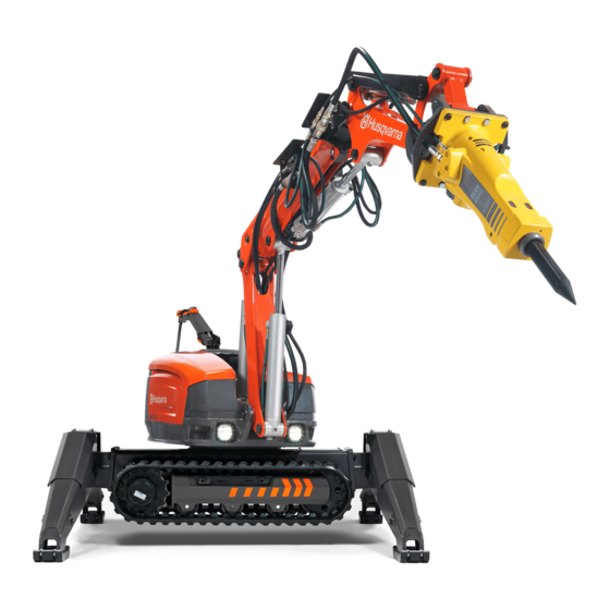
Husqvarna DXR-310 Operator's Manual
Husqvarna power hammer user manual
Hide thumbs
Also See for DXR-310:
- Price list (48 pages) ,
- Operator's manual (84 pages) ,
- Quick start manual (2 pages)

Related Manuals for Husqvarna DXR-310


Summary of Contents for Husqvarna DXR-310
- Page 1 DXR-310 Please read the Operator’s Manual carefully and make sure you understand the instructions before using the machine. English HUSQVARNA CONSTRUCTION PRODUCTS...
-
Page 3: Table Of Contents
Contents INTRODUCTION Dear Customer ... 4 Good service ... 4 Serial Number ... 4 Applications ... 4 User responsibility ... 4 The manufacturer’s reservation ... 4 KEY TO SYMBOLS Symbols on the machine ... 5 SAFETY INSTRUCTIONS Warning instructions ... 6 Protective equipment ... -
Page 4: Introduction
Good service Husqvarna products are sold all over the world and ensures that you, the customer, get the best support and service. When you need spare parts or advice on service or warranty issues, go to www.husqvarnacp. -
Page 5: Key To Symbols
Symbols on the machine WARNING! The machine can be danger- ous if used incorrectly or carelessly, and can cause serious or fatal injury to the operator or others. Please read the Operator’s Manual care- fully and make sure you understand the instructions before using the machine. -
Page 6: Safety Instructions
Warning instructions Warning WARNING! Used if there is a risk of serious injury or death for the operator or damage to the surroundings if the instructions in the manual are not followed. Important IMPORTANT! Used if there is a risk of injury to the operator or damage to the surroundings if the instructions in the manual are not followed. -
Page 7: General Safety Warnings
Use the safety instructions as guidelines and support so that you can detect possible risks yourself and take measures to prevent them. Let your Husqvarna dealer regularly check the ma- chine and make essential adjustments and repairs. Management and operator... -
Page 8: General Working Instructions
General working instructions WARNING! Read all safety warnings and all instructions. Neglecting to follow the warnings and instruc- tions can lead to serious injury or death for the operator or others.. This section describes basic safety directions for using the machine. This information is never a substi- tute for professional skills and experience. -
Page 9: Personal Safety
Personal safety • Never use the machine if you are tired, if you have consumed alcohol, or if you are taking other drugs or medication that can affect your vision, judge- ment or co-ordination. • Wear personal protective equipment. See instruc- tions under the heading ”Personal protective equipment”. - Page 10 Manoeuvring General • If several machines are used at the same workplace there is a risk of mixing up the remote controls. Switch on the current to the remote control and the machine. Press the horn to see which machine is connected to the remote control.
- Page 11 Proximity to edges • Inadequate surfaces, incorrect operation, etc. can cause the machine to slide. Exercise particular cau- tion when working close to shafts, beside trenches or when working at height. • Always anchor the machine and loose tools when working close to edges.
- Page 12 Transport and storage Lifting the machine • When lifting the machine there is a risk of injuring persons or damaging the machine or the surround- ings. Defi ne the risk area and check that nobody is present within the area when lifting. •...
-
Page 13: The Machine's Safety Features
Maintenance and service Most accidents involving machines occur during trou- ble shooting, service and maintenance as staff have to locate themselves within the machine’s risk area. Prevent accidents by being alert and by planning and preparing the work. You can also refer to ’Preparations for maintenance and service”... - Page 14 Identity code The remote control and the machine are connected by means of a pre-programmed ID code. The ID code ensures that the right remote control is used for the right machine. If several machines are used at the same workplace there is a risk of mixing up the remote controls.
-
Page 15: External Environmental Factors
External environmental factors Temperature The ambient temperature, both heat and cold, affects the machine’s operational reliability. Temperature variations also have an impact as they produce an increased risk of condensation forming in the ma- chine’s tanks. Heat NB! There is an increased risk of overheating in warm environments. -
Page 16: Presentation
The machine’s functions The machine’s functions are operated by means of interaction between the hydraulic system, the electric system and the control system. A brief description of the machine’s functions follows below. Arm system The arm system is divided into three parts in order to provide extensive movement, a long reach and com- pactness. -
Page 17: What Is What In The Machine
What is what in the machine 1. Hydraulic tank 2. Lubrication pump for lubricating the hammer (accessory) 3. Arm 1 4. Arm 2 5. Telescopic arm 6. Arm 3 7. Cylinders 8. Valve block 9. Slew motor 10. Tool attachment 11. -
Page 18: Hydraulic System
HYDRAULIC SYSTEM General The task of the hydraulic system is to operate the ma- chine’s functions by means of hydraulic pressure and fl ow. The system consists of hydraulic pump, tank, cooler, hydraulic motor, hydraulic cylinders, fi lters and valves of various kinds. Hoses or pipes connect the components with each other. -
Page 19: The Machine's Hydraulic System
The machine’s hydraulic system 1. Air fi lter 2. Oil fi lter 3. Hydraulic tank 4. Cylinder 1 5. Cylinder 5 6. Cylinder 4 7. Cylinder 3 8. Cylinder 2 9. Valve block 1 10. Slew motor 11. Valve block 2 12. -
Page 20: Electrical System
ELECTRIC SYSTEM General The electric system consists of a high-voltage circuit and a low-voltage circuit. High-voltage circuit High-voltage is used as a power source for both the electric motor and the low-voltage circuit. An automat- ic phase rotation change-over switch ensures that the electric motor has the correct rotation direction. -
Page 21: The Machine's Electric System
The machine’s electric system 1. Aerial 2. Electric cabinet 3. Pressure switch 4. Temperature sensor 5. Warning light 6. Power cable 7. Electric motor 8. Control module 9. Radio module ELECTRIC SYSTEM 10. Work lighting 11. Pressure sensor 12. External tool 13. -
Page 22: Control System
General The remote control, the electronics unit and the pilot control valves are the main components in the control system. The signals from the remote control are trans- mitted to the machine via bluetooth or via a cable. The electronic unit in the machine transmits the signals via the pilot control valves to the hydraulic system by converting electric current into hydraulic pressure. -
Page 23: What Is What On The Remote Control
What is what on the remote control 1. Left joystick - left button 2. Left joystick - right button 3. Display 4. Right joystick - left button 5. Right joystick - right button 6. Right joystick 7. Main switch 8. Machine stop CONTROL SYSTEM 9. -
Page 24: Symbols On The Remote Control
Symbols on the remote control 1. Arm 2 telescope out 2. Arm 2 down 3. Right track operation forward 4. Arm 1 and arm 2 out 5. Angle tool outwards 6. Right outrigger down 7. Front/rear right outrigger down 8. Arm 1 out 9. -
Page 25: Starting And Stopping
STARTING AND STOPPING Before starting The following points should be checked when working at a new site and every morning before starting: • Carrying out daily inspections. • Examine the machine for transport damage. • Check that the machine’s safety features are intact. Refer to ’The machine’s safety features”... -
Page 26: Operation
Operating modes The machine can be operated in three different modes: transport mode, set-up mode and work mode. All commands in each of the modes are described in this section. • Work mode - In this mode you can operate every- thing except the caterpillar tracks and outriggers. -
Page 27: Work Mode
OPERATION Work mode Rotate tower anticlockwise Rotate tower clockwise Arm 1 in Arm 1 out Arm 2 down Arm 2 up Arm 2 telescope out Arm 2 telescope in Arm 1 and arm 2 out Arm 1 and arm 2 in Arm 3 up Arm 3 down Angle tool inwards*... -
Page 28: Set-Up Mode
OPERATION Set-up mode Track operation Right track operation forward Right track operation backwards Left track operation forward Left track operation backwards Outriggers Right outrigger down Right outrigger up Rear right outrigger down Rear right outrigger up Front right outrigger down Front right outrigger up Left outrigger down Left outrigger up... -
Page 29: Transport Mode
OPERATION Transport mode Right track forward left track forward Right track backwards left track forward Rotate tower clockwise Rotate tower anticlockwise Caterpillar tracks forward Caterpillar tracks backwards Arm 1 out Arm 1 in Arm 2 down Arm 2 up Arm 2 telescope out Arm 2 telescope in Arm 1 and arm 2 out Arm 1 and arm 2 in... -
Page 30: Tools
General IMPORTANT! Please read the operator’s manual carefully and make sure you understand the instructions before using the machine. You should also read and understand the manual that accompanies the tool. Ensure that the tool’s and the machine’s per- formance (weight, hydraulic pressure, fl ow etc) are compatible. -
Page 31: Changing Tools
Changing tools IMPORTANT! Changing tools may mean that the operator has to be within the machine’s risk area. Ensure that nobody unintentionally starts the machine while the tool is being changed. Keep a sharp watch on the machine and be prepared to turn it off. Guard hands and feet against crushing. -
Page 32: Settings
Track widener The machine is equipped with track wideners for increased stability when working with the machine. Width with track widener: 1110 mm (44 in) Width without track widener: 780 mm (31 in) Fitting the track widener • Let down the outriggers. •... -
Page 33: Menu System
SETTINGS Menu system English -... -
Page 34: Operational Settings
Operational settings LCD Adjustment Use the arrows up and down to adjust the display’s contrast and brightness. Software version This shows the version of the software in the terminal and the two control modules. Tuning The following components can be adjusted in the Service Menu under Tuning. -
Page 35: Maintenance And Service
MAINTENANCE AND SERVICE General WARNING! Most accidents involving machines occur dur- ing trouble shooting, service and maintenance as staff have to locate themselves within the machine’s risk area. Prevent accidents by being alert and by planning and preparing the work. If service operations or trouble shooting does not require the machine to be switched on, the power cable must be removed and positioned... -
Page 36: Cleaning
MAINTENANCE AND SERVICE Cleaning IMPORTANT! Turn off the motor. Disconnect the power cable and place it so that it cannot be connected by mistake. The area around the machine must be free of dirt in order to minimize the risk of slipping. Use suitable personal protective equipment. -
Page 37: Service Schedule
MAINTENANCE AND SERVICE Service schedule The service schedule is based on the machine’s operating time. More frequent service intervals might be necessary when working in dusty or hot environments and in conjunction with work that generates high temperatures. A description of how the operations are to be performed is to be found in the service review. Daily inspection Daily maintenance must also be carried out after transportation. - Page 38 MAINTENANCE AND SERVICE Weekly service Carry out a daily inspection as per the service schedule before you carry out the weekly service. Lubrication Cylinders and shafts in lower part and outriggers Drive, track sides and track tensioning Gear ring Cracks Drive, track sides and track tensioning Mountings Drive, track sides and track tensioning...
- Page 39 MAINTENANCE AND SERVICE After the fi rst 100 hours Change After the fi rst 100 hours the following maintenance should be carried out, subsequently every 1,000 hours. Slew motor, slew reduction gear unit - oil change Drive motor, drive gear – oil change 250 hours service Carry out the weekly service as per the service schedule before you perform the 250 hours service.
-
Page 40: Service Review
MAINTENANCE AND SERVICE Service review WARNING! Ensure that nobody starts the machine while service is taking place. Turn off the motor when the machine has been moved to the desired location. Disconnect the power cable and place it so that it cannot be connected by mistake. Lubrication The machine can be moved to a position to access all grease nipples (see picture). - Page 41 MAINTENANCE AND SERVICE Mountings General Check that all components are properly secured by feeling, pulling etc. Keep a look out for wear damage. This can be caused by components coming loose. • A bolted joint that is secured with adhesive should not be tightened.
- Page 42 MAINTENANCE AND SERVICE Level check Position the machine on a fl at surface. Clean the component before it is opened for reading or fi lling in order to prevent dirt entering the system. If the oil level is low, refi ll with the type and quality as per the ’Hydraulic fl...
- Page 43 MAINTENANCE AND SERVICE Leakage General NB! Leakage can cause serious mechanical break- downs and an increased risk of slipping. Wash the machine regularly to increase the chance of detecting leakage at an early stage. Deal with leaks as quickly as possible and refi...
- Page 44 MAINTENANCE AND SERVICE Functional inspection General Functional inspections must ensure that the machine’s functions are intact. Brake functions • Check the drive brake’s function by operating the machine on a slope. Release the joysticks. The ma- chine should then be braked and remain stationary. •...
- Page 45 MAINTENANCE AND SERVICE Change IMPORTANT! Chemicals such as degreasing agent, grease, fuel, glycol and hydraulic fl uid can give rise to allergies in conjunction with repeated skin con- tact. Avoid contact with the skin, use protective equipment. General Changing liquids and fi lters must be done in such a way that the machine’s hydraulic system and the sur- rounding environment are not damaged.
- Page 46 Oil fi lter IMPORTANT! Allow the machine to cool. Hot oil can cause severe burn injuries. • Undo the air fi lter so that the overpressure in the tank is discharged. • Thoroughly clean the outside of the fi lter and the surrounding parts.
-
Page 47: Trouble Shooting
Error messages There are two types of error messages that can appear on the display: • Service messages - These messages do not represent any direct danger for the operator or the machine. • Warnings - These warn of faults or safety defects that can cause mechanical damage. -
Page 48: Troubleshooting Schedule
Trouble shooting guide WARNING! Most accidents involving machines occur during trouble shooting, service and maintenance as staff have to locate themselves within the machine’s risk area. Prevent accidents by being alert and by planning and prepar- ing the work. You can also refer to ’Preparations for maintenance and service” in the ’Maintenance and serv- ice”... - Page 49 An individual function Restriction in a hydraulic is running slowly. hose. Fault in the pilot control valve. Contact your service agent. An individual function Joystick in an operative posi- is not working. tion when starting the remote control. Fault in the pilot control valve. Contact your service agent. The machine sinks on Leaking direction control valves the outriggers...
-
Page 50: Technical Data
Guide values for mains connection The power cable must be dimensioned by a qualifi ed person in accordance with national and local regulations. The mains socket to which the machine is connected must be dimensioned for the same amperage as the machine’s electrical socket and extension cable, e.g. -
Page 51: Hydraulic Fl Uid And Lubricant
Hydraulic fl uid and lubricant Hydraulic fl uid Quality Min. starting temp, ºC/ºF Mineral oil ISO VG32 -20/-4 Mineral oil ISO VG46 -13/9 Mineral oil ISO VG68 -10/14 Always ask the machine manufacturer before using a type of hydraulic fl uid other than those mentioned above. The quality of hydraulic fl... -
Page 52: Technical Data
Technical data General Rotation speed, rpm Transport speed max., km/h / mph Angle of inclination, max. Hydraulic system Volume hydraulic system, l/gal Pump type Pump fl ow max.*, l/min /gal/min Electric motor Type Power, kW Speed, rpm Voltage, V/frequency, Hz Current, A Control system Control type... - Page 53 Noise emissions Noise emissions in the environment measured as sound power (L Machine without tool Sound power level, measured dB(A) Sound power level, guaranteed L Machine with tool (hydraulic hammer) Sound power level, measured dB(A) Sound power level, guaranteed L Sound power level Sound level 10 m from the machine’s tools*, dB(A) * The stated value refers to work with a hydraulic hammer.
- Page 54 TECHNICAL DATA - English...
- Page 55 TECHNICAL DATA English -...
-
Page 56: Ec-Declaration Of Conformity
Husqvarna Construction Products, SE-433 81 Göteborg, Sweden, tel: +46-31-949000, declares under sole respon- sibility that the Husqvarna DXR-310 dating from 2009 serial numbers and onwards (the year is clearly stated on the rating plate, followed by the serial number), complies with the requirements of the COUNCIL’S DIRECTIVES: - of June 22, 1998 “relating to machines”... - Page 58 ´®z+SXh¶6Q¨ ´®z+SXh¶6Q¨...
- Page 60 www.husqvarnacp.com 1151567-26 2009-03-16 ´®z+SXh¶6Q¨ ´®z+SXh¶6Q¨...