Table of Contents
Advertisement
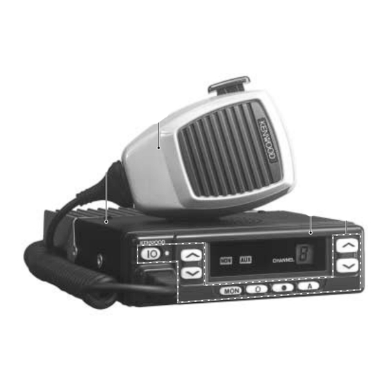
VHF FM TRANSCEIVER
TK-760HG/762HG
SERVICE MANUAL
REVISED
This service manual is the same as the K and M market, TK-760HG/
762HG (B51-8538-00) service manual with the exception of new K2
market.
TK-760HG (K)
TK-762HG (K)
Cabinet (Upper)
(A01-2165-13)
Microphone
(T91-0621-05)
Cabinet (Upper)
(A01-2165-13)
Microphone
(T91-0621-05)
© 2000-10 PRINTED IN JAPAN
B51-8538-10 ( N ) 1724
Panel assy
(A62-0642-03)
Key top
(K29-5343-02)
Panel assy
(A62-0731-03)
Key top
(K29-5344-02)
Advertisement
Table of Contents

Related Manuals for Kenwood TK-760HG


Summary of Contents for Kenwood TK-760HG
- Page 1 SERVICE MANUAL REVISED © 2000-10 PRINTED IN JAPAN B51-8538-10 ( N ) 1724 This service manual is the same as the K and M market, TK-760HG/ 762HG (B51-8538-00) service manual with the exception of new K2 market. TK-760HG (K) Microphone...
-
Page 2: Table Of Contents
EXPLODED VIEW ......................16 PACKING ........................18 ADJUSTMENT ....................... 19 PC BOARD VIEWS DISPLAY UNIT (X54-3270-10) : TK-760HG .............. 28 DISPLAY UNIT (X54-3280-10) : TK-762HG .............. 29 PLL/VCO (X58-4670-XX) ..................30 TX-RX UNIT (X57-5950-XX) (A/2) ................31 TX-RX UNIT (X57-5950-XX) (B/2) ................37 SCHEMATIC DIAGRAM .................... -
Page 3: Operating Features
After finishing transmission, the transceiver receivers for 5 seconds. The transceiver mutes the speaker while receiv- ing. Following the above sequence, the transceiver contin- ues to transmit and receive. Emergency mode system chart (TK-760HG) Foot switch 1 push (Hold it down for about one second.) Emergency mode... -
Page 4: Realignment
REMOTE/TXD HOOK/RXD 1. Turn the master TK-760HG power ON with the [ ] key held down. If the password is set to the TK-760HG, the TK-760HG displays “CLN LOCK”. If the password is not set, the TK-760HG displays “CLONE”. -
Page 5: Installation
TK-760HG/762HG INSTALLATION Ignition Sense Cable (KCT-18 : Option) Operation when KCT-18 R134 R135 is connected The KCT-18 is an optional cable for enabling the ignition Enable ← KCT-18 cannot Enable function. The ignition function lets you turn the power to the... - Page 6 TK-760HG/762HG INSTALLATION Modifying the Transceiver • Public address • Horn alert The signal from pin 13 of IC9 on the TX-RX unit drives PA relay K1 in the KAP-1 and switches the audio power ampli- The signal from pin 4 of IC9 on the TX-RX unit turns Q5...
-
Page 7: Emergency Mode
TK-760HG/762HG INSTALLATION Emergency Mode Transceiver Modification Procedure TX-RX unit B/2 Foil side • Install the foot switch Install the foot switch through the KCT-19 and KCT-18. When the switch is treaded on, the radio enters the emer- gency mode. • Change the power switch circuit... -
Page 8: Parts List
Les articles non mentionnes dans le Parts No. ne sont pas fournis. Y : AAFES (Europe) X: Australia M: Other Areas Teile ohne Parts No. werden nicht geliefert. TK-760HG/762HG DISPLAY UNIT (X54-3270-10) : TK-760HG, DISPLAY UNIT (X54-3280-10) : TK-762HG Desti- Desti- Ref. No. Address Parts No. - Page 9 TX-RX UNIT (X57-5950-XX) C92-0546-05 CHIP-TAN 68UF 6.3WV CK73GB1H103K CHIP C 0.010UF -14 : TK-760HG K,M -15 : TK-762HG K C92-0004-05 CHIP-TAN 1.0UF 16WV -16 : TK-760HG K2 -17 : TK-762HG K2 C100 CK73GB1H102K CHIP C 1000PF D509-514...
- Page 10 CK73FF1C105Z CHIP C 1.0UF C252 CK73GB1C104K CHIP C 0.10UF C571,572 CK73GB1H102K CHIP C 1000PF C259 CK73GB1C104K CHIP C 0.10UF C573 CK73FB1H563K CHIP C 0.056UF C265 CK73GB1H102K CHIP C 1000PF C574 CC73GCH1H470J CHIP C 47PF TK-760HG : K,K2,M TK-762HG : K,K2...
- Page 11 SMALL FIXED INDUCTOR (0.33UH) R92-1252-05 CHIP R 0 OHM L34-4530-05 COIL RK73GB1J103J CHIP R 1/16W L40-1581-86 SMALL FIXED INDUCTOR (0.15UH) RK73GB1J152J CHIP R 1.5K 1/16W L40-4785-85 SMALL FIXED INDUCTOR (0.47UH) RK73GB1J103J CHIP R 1/16W TK-760HG : K,K2,M TK-762HG : K,K2...
- Page 12 RK73FB2A821J CHIP R 1/10W RK73GB1J223J CHIP R 1/16W R161 RK73GB1J334J CHIP R 330K 1/16W RK73GB1J271J CHIP R 1/16W R162 RK73GB1J333J CHIP R 1/16W R100,101 RK73GB1J101J CHIP R 1/16W R163 R92-0670-05 CHIP R 0 OHM TK-760HG : K,K2,M TK-762HG : K,K2...
- Page 13 CHIP R 1/16W R530 RK73GB1J473J CHIP R 1/16W R593 RK73GB1J181J CHIP R 1/16W R531 RK73GB1J394J CHIP R 390K 1/16W R594 RK73GB1J392J CHIP R 3.9K 1/16W R532 RK73GB1J103J CHIP R 1/16W R595 RK73GB1J181J CHIP R 1/16W TK-760HG : K,K2,M TK-762HG : K,K2...
- Page 14 DTA114EKA DIGITAL TRANSISTOR D501-504 MA2S111 DIODE 3SK241(R) D505 MA2S111 DIODE 2SB1132(Q,R) TRANSISTOR D506,507 MA2S111 DIODE DTC114EKA DIGITAL TRANSISTOR D508 MA742 DIODE 2SC2412K TRANSISTOR D523 DAN202U DIODE 2SB1565(E,F) TRANSISTOR D524,525 HSB123 DIODE DTC114EKA DIGITAL TRANSISTOR TK-760HG : K,K2,M TK-762HG : K,K2...
- Page 15 L34-4548-05 AIR-CORE COIL L116 L34-4549-05 AIR-CORE COIL R101,102 RK73GB1J101J CHIP R 1/16W R103 RK73GB1J102J CHIP R 1.0K 1/16W R104 RK73GB1J470J CHIP R 1/16W R105 RK73GB1J154J CHIP R 150K 1/16W R106 RK73GB1J470J CHIP R 1/16W TK-760HG : K,K2,M TK-762HG : K,K2...
-
Page 16: Exploded View
TK-760HG/762HG EXPLODED VIEW (TK-760HG) Parts with the exploded numbers larger than 700 are not supplied. - Page 17 TK-760HG/762HG EXPLODED VIEW (TK-762HG) Parts with the exploded numbers larger than 700 are not supplied.
-
Page 18: Packing
TK-760HG/762HG PACKING 45 Microphone 13 DC cord (T91-0621-05) : K,K2 33 Protection bag (E30-3339-05) (H25-0720-04) 19 Fuse (F51-0017-05) x 2 5 Cap (B09-0235-05) 38 Bracket (J29-0627-23) 32 Inner packing case (H12-1391-03) 36 Holder (J19-1584-05) 42 Screw set (N99-0395-05) 31 Polystyrene foamed fixture (R) -
Page 19: Adjustment
TK-760HG/762HG ADJUSTMENT • Signalling Test Mode (TK-760HG Only) Signalling No. Test Mode Operating Features None None This transceiver has a test mode. To enter test mode, press [SCN] key and turn power on. Hold [SCN] key un- None 100Hz square til test channel No. - Page 20 TK-760HG/762HG ADJUSTMENT Tuning Mode Display Function name FREQ_ _XX Frequency adj. HPOW_XXX H.POW_XXX H.P.OW_XXX H.P.O.W_XXX H.P.O.W._XXX H.P.O.W._.XXX RF high power Hi power (L) Hi power (L') Hi power (C) Hi power (H') Hi power (H) [D/A] [D/A] [D/A] [D/A] [D/A] LPOW_XXX L.POW_XXX...
- Page 21 TK-760HG/762HG ADJUSTMENT Test Equipment Required for Alignment Test Equipment Major Specifications 1. Standard Signal Generator Frequency Range 136 to 174MHz (SSG) Modulation Frequency modulation and external modulation Output –127dBm/0.1µV to greater than –7dBm/100mV 2. Power Meter Input Impedance 50Ω Operation Frequency...
- Page 22 TK-760HG/762HG ADJUSTMENT Adjustment Location Adjustment Point Switch (TK-760HG) Volume Channel Power up/down Display up/down TX-RX UNIT (A/2) MIC jack Programmable function keys Note TC106 • Flash memory PLL/VCO The firmware program (User mode, Test mode, Tuning RSSI mode, etc.) and the data programmed by the FPU (KPG-56D) TC109 for the flash memory, is stored in memory.
- Page 23 TK-760HG/762HG ADJUSTMENT Common Section Since the TK-762HG cannot be tuned from the panel, the FPU (KPG-56D) should be used for adjustment. Measurement Adjustment Item Condition Specifications/Remarks Test- Unit Terminal Unit Parts Method equipment ± 0.1V 1. PLL lock 1) Set test mode TX-RX CV TC106 7.5V...
- Page 24 TK-760HG/762HG ADJUSTMENT Measurement Adjustment Item Condition Specifications/Remarks Test- Unit Terminal Unit Parts Method equipment 3) “S.Q.L.3._.” Rear Front CH / Adjust to the Adjust [ *** ] panel panel squelch threshold SSG freq’ AF VTVM point. : 173.950MHz K,M Distortion (EXT.SP)
- Page 25 TK-760HG/762HG ADJUSTMENT Transmitter Section Measurement Adjustment Item Condition Specifications/Remarks Test- Unit Terminal Unit Parts Method equipment 1. Frequency 1) Set test mode Power meter Rear Front CH / Check 161.100MHz±50Hz K Select “FREQ” in tuning mode. F. counter panel panel 149.100MHz±50Hz K2...
- Page 26 TK-760HG/762HG ADJUSTMENT Measurement Adjustment Item Condition Specifications/Remarks Test- Unit Terminal Unit Parts Method equipment 6. Modulation 1) Set test mode Power meter Rear Front CH / Make the de- (Wide/Narrow) balanced MIC input : OFF Deviation panel panel modulation • Wide Select “BAL”...
- Page 27 TK-760HG/762HG ADJUSTMENT Measurement Adjustment Item Condition Specifications/Remarks Test- Unit Terminal Unit Parts Method equipment ± 50Hz (Wide/Narrow) 2) “_.F.Q.T” Power meter Rear Front CH / 0.75kHz PTT : ON Deviation panel panel Adjust [ *** ] meter Oscilloscope 3) “_.F.Q.T._.”...
-
Page 28: Display Unit (X54-3270-10) : Tk-760Hg
TK-760HG/762HG PC BOARD VIEWS DISPLAY UNIT (X54-3270-10) : TK-760HG DISPLAY UNIT (X54-3270-10) : TK-760HG Component side view Foil side view C806 C807 C806 C807 R808 R808 R809 R809 CN801 CN801 C801 C801 R801 R801 C802 C802 C803 C805 C805 C803... -
Page 29: Display Unit (X54-3280-10) : Tk-762Hg
TK-760HG/762HG PC BOARD VIEWS DISPLAY UNIT (X54-3280-10) : TK-762HG DISPLAY UNIT (X54-3280-10) : TK-762HG PLL/VCO (X58-4670-XX) -10 : K,M -11 : K2 Component side view Component side view Foil side view J72-0676-02 C115 C119 L111 L109 CN101 L103 C104 L112... - Page 30 TK-760HG/762HG PC BOARD VIEW TX-RX UNIT (X57-5950-XX) (A/2) Component side view -14 : TK-760HG K,M -15 : TK-762HG K -16 : TK-760HG K2 -17 : TK-762HG K2 Ref. No. Address Ref. No. Address Ref. No. Address Ref. No. Address IC13...
-
Page 31: Tx-Rx Unit (X57-5950-Xx) (A/2)
Ref. No. Address Ref. No. Address Ref. No. Address Ref. No. Address Q16 13M D16 11N -14 : TK-760HG K,M -15 : TK-762HG K -16 : TK-760HG K2 -17 : TK-762HG K2 D28 10Q Q18 13N D18 12Q Component side IC400... - Page 32 Ref. No. Address Ref. No. Address Ref. No. Address Ref. No. Address Component side view + Foil side IC12 -14 : TK-760HG K,M -15 : TK-762HG K -16 : TK-760HG K2 -17 : TK-762HG K2 IC13 IC14 IC15 Q10 13M Component side...
-
Page 33: Tx-Rx Unit (X57-5950-Xx) (B/2)
TK-760HG/762HG PC BOARD VIEWS TX-RX UNIT (X57-5950-XX) (B/2) Component side view -14 : TK-760HG K,M -15 : TK-762HG K -16 : TK-760HG K2 -17 : TK-762HG K2 D512 J72-0759-12 B/2 D511 R566 C543 C632 L501 R567 R560 C501 C542 IC510... - Page 34 TK-760HG/762HG PC BOARD VIEW TX-RX UNIT (X57-5950-XX) (B/2) Component side view + Foil side -14 : TK-760HG K,M -15 : TK-762HG K -16 : TK-760HG K2 -17 : TK-762HG K2 J72-0759-12 B/2 D512 R550 D511 R548 R501 R553 R612 C534...
-
Page 35: Schematic Diagram
TK-760HG SCHEMATIC DIAGRAM Note : Components marked with a dot (·) are parts of patterun 1. - Page 36 TK-762HG SCHEMATIC DIAGRAM Note : Components marked with a dot (·) are parts of patterun 1.
-
Page 37: Block Diagram
TK-760HG/762HG TK-760HG/762HG TK-760HG/762HG BLOCK DIAGRAM... -
Page 38: Level Diagram
TK-760HG/762HG TK-760HG/762HG LEVEL DIAGRAM Receiver Section Center Frequency 49.95MHz 450kHz Audio Frequency To make measurements in the RF section, connect the RF level meter. In the RF section, use a 0.01µF coupling capacitor. (The display shows the SSG input value required to obtain 12dB SINAD.) -
Page 39: Terminal Function
TK-760HG/762HG TERMINAL FUNCTION CN1 (TX-RX Unit) CN3 (TX-RX Unit) Pin No. Name Function Pin No. Name Function DC 8V output. Horn alert/call output. DC 5V output. Ground. AUX5 SMRD : Reset output. *1 Switched B+, DC 13.6V output, Maximum 1A. -
Page 40: Specifications
M : 146 to 174MHz Number of Channels ......TK-762HG : Maximum 8 channels TK-760HG : Maximum 128 channels Number of Groups ......TK-760HG : Maximum 128 groups Channel Spacing ......... Wide : 25, 30kHz Narrow : 12.5, 15kHz PLL Channel Stepping ......2.5, 3.75, 5, 6.25, 7.5kHz Operating Voltage ....... - Page 41 Mechelsesteenweg 418 B-1930 Zaventem, Belgium KENWOOD ELECTRONICS FRANCE S.A. 13, Boulevard Ney, 75018 Paris, France KENWOOD ELECTRONICS U.K. LIMITED KENWOOD House, Dwight Road, Watford, Herts., WD1 8EB United Kingdom KENWOOD ELECTRONICS EUROPE B.V. Amsterdamseweg 37, 1422 AC Uithoorn, The Netherlands KENWOOD ELECTRONICS ITALIA S.p.A.