Table of Contents
Advertisement
Advertisement
Table of Contents

Related Manuals for Husqvarna LTH125


Summary of Contents for Husqvarna LTH125
- Page 1 LTH125 Owner’s Manual...
- Page 2 Safe Operation Practices for Ride-On Mowers IMPORTANT: THIS CUTTING MACHINE IS CAPABLE OF AMPUTATING HANDS AND FEET AND THROWING OBJECTS. FAILURE TO OBSERVE THE FOLLOWING SAFETY INSTRUCTIONS COULD RESULT IN SERIOUS INJURY OR DEATH. GENERAL OPERATION • Read, understand, and follow all instructions in the manual and on the machine before starting.
-
Page 3: Safety Rules
Please read and retain this manual. The instructions will enable you to assemble and maintain your tractor prop- erly. Always observe the "SAFETY RULES". MODEL NUMBER LTH125 SERIAL NUMBER ____________________________________ DATE OF PURCHASE __________________________ THE MODEL AND SERIAL NUMBERS WILL BE FOUND ON A PLATE UNDER THE SEAT. -
Page 4: Table Of Contents
TABLE OF CONTENTS SAFETY RULES... 2 PRODUCT SPECIFICATIONS ... 3 CUSTOMER RESPONSIBILITIES ... 3, 15-19 ASSEMBLY ... 6-9 OPERATION ... 10-14 MAINTENANCE SCHEDULE ... 15 INDEX Adjustments: Brake ... 22 Carburetor ... 25 Mower: Front-To-Back ... 21 Side-To-Side ... 21 Throttle Control Cable ... - Page 5 CONTENTS OF HARDWARE PACK...
-
Page 6: Assembly
Your new tractor has been assembled at the factory with exception of those parts left unassembled for shipping purposes. To ensure safe and proper operation of your tractor, all parts and hardware you assemble must be tightened securely. Use the correct tools as necessary to insure proper tightness. TOOLS REQUIRED FOR ASSEMBLY A socket wrench set will make assembly easier. -
Page 7: How To Set Up Your Tractor
HOW TO SET UP YOUR TRACTOR PREPARE BATTERY (See Fig. 2) CAUTION: Wear eye and face shield. Wash hands or clothing immediately if accidentally in contact with battery acid. Do not smoke. Fumes from charged battery acid are explosive. Read the instructions included with the battery vent caps. - Page 8 INSTALL BATTERY (See Figs. 4 & 5) CAUTION: Do not short battery termi- nals. Before installing battery, remove metal bracelets, wristwatch bands, rings, etc. Positive terminal must be connected first to prevent sparking from acciden- tal grounding. • Lift seat to raised position. •...
- Page 9 INSTALL MULCHER PLATE (See Figs.6 & 7) • Install two latch hooks to mulcher plate using screw, washer, lock washer, and weld nut as shown. NOTE: Pre-assemble weld nut to latch hook by inserting weld nut from the top with hook pointing down. •...
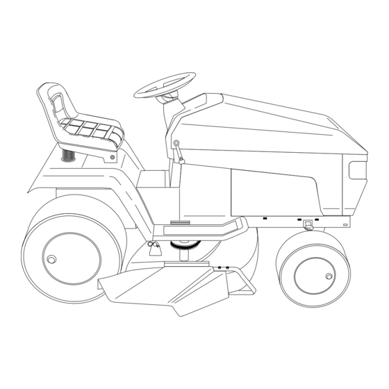
- Page 10 KNOW YOUR TRACTOR READ THIS OWNER'S MANUAL AND SAFETY RULES BEFORE OPERATING YOUR TRACTOR Compare the illustrations with your tractor to familiarize yourself with the locations of various controls and adjustments. Save this manual for future reference. THROTTLE/CHOKE LIFT LEVER CONTROL PLUNGER ATTACHMENT LIFT...
-
Page 11: How To Use Your Tractor
The operation of any tractor can result in foreign objects thrown into the eyes, which can result in severe eye damage. Always wear safety glasses or eye shields while operating your tractor or performing any adjustments or repairs. We recom- mend a wide vision safety mask for over the spectacles or standard safety glasses. -
Page 12: Before Starting The Engine
TO OPERATE MOWER (See Fig. 10) Your tractor is equipped with an operator presence sensing switch. Any attempt by the operator to leave the seat with the engine running and the mower clutch engaged will shut off the engine. • Select desired height of cut. -
Page 14: Mowing Tips
MOWING TIPS • Tire chains cannot be used when the mower housing is attached to tractor. • Mower should be properly leveled for best mowing performance. See "TO LEVEL MOWER HOUSING" in the Service and Adjustments section of this manual. •... -
Page 15: Lubrication Chart
CUSTOMER RESPONSIBILITIES GENERAL RECOMMENDATIONS The warranty on this tractor does not cover items that have been subjected to operator abuse or negligence. receive full value from the warranty, operator must maintain tractor as instructed in this manual. Some adjustments will need to be made periodically to properly maintain your tractor. -
Page 16: Customer Responsibilities
CUSTOMER RESPONSIBILITIES TRACTOR Always observe safety rules when performing any mainte- nance. BRAKE OPERATION If tractor requires more than six (6) feet stopping distance at high speed in highest gear, then brake must be adjusted. (See "TO ADJUST BRAKE" in the Service and Adjust- ments section of this manual). - Page 17 CUSTOMER RESPONSIBILITIES BATTERY (See Fig. 16) Your tractor has a battery charging system which is suffi- cient for normal use. However, periodic charging of the battery with an automotive charger will extend it's life. • Acid solution level in each battery cell should be even with bottoms of vent wells.
-
Page 18: Carburetor
CUSTOMER RESPONSIBILITIES ENGINE LUBRICATION Only use high quality detergent oil rated with API service classification SF or SG. Select the oil's SAE viscosity grade according to your expected operating temperature. NOTE: Although multi-viscosity oils (5W30, 10W30 etc.) improve starting in cold weather, these multi-viscosity oils will result in increased oil consumption when used above 32°F. - Page 19 CUSTOMER RESPONSIBILITIES ENGINE COOLING FINS (See Fig. 19) Remove any dust, dirt or oil from engine cooling fins to prevent engine damage from overheating. • Remove screws from blower housing and lift housing and dipstick tube assembly off engine. • Cover oil fill opening to prevent entry of dirt.
-
Page 20: Service And Adjustments
SERVICE AND ADJUSTMENTS CAUTION: BEFORE PERFORMING ANY SERVICE OR ADJUSTMENTS: • Depress clutch/brake pedal fully and set parking brake. • Place motion control lever in neutral (N) position. • Place attachment clutch in "DISENGAGED" position. • Turn ignition key "OFF" and remove key. •... -
Page 21: Side-To-Side
SERVICE AND ADJUSTMENTS TO LEVEL MOWER HOUSING Adjust the mower while tractor is parked on level ground or driveway. Make sure tires are properly inflated (See “PRODUCT SPECIFICATIONS” on page 3 of this manual). If tires are over or underinflated, you will not properly adjust your mower. - Page 22 SERVICE AND ADJUSTMENTS TO REPLACE MOWER BLADE DRIVE BELT (See Fig. 26) The mower blade drive belt may be replaced without tools. Park the tractor on level surface. Engage parking brake. BELT REMOVAL - • Remove mower from tractor (See “TO REMOVE MOWER”...
- Page 23 SERVICE AND ADJUSTMENTS TO ADJUST MOTION CONTROL LEVER (See Fig.29) The motion control lever has been preset at the factory and adjustment should not be necessary. If for any reason the motion control lever will not hold its position while at a selected speed, it may be adjusted at the friction pack located on the right side of transmission.
- Page 24 SERVICE AND ADJUSTMENTS TO START ENGINE WITH A WEAK BATTERY (See Fig. 31) CAUTION: Lead-acid batteries gener- ate explosive gases. Keep sparks, flame and smoking materials away from bat- teries. Always wear eye protection when around batteries. If your battery is too weak to start the engine, it should be recharged.
-
Page 25: Throttle Control Cable
SERVICE AND ADJUSTMENTS ENGINE TO ADJUST THROTTLE CONTROL CABLE (See Fig.33) The throttle control has been preset at the factory and adjustment should not be necessary. Check adjustment as described below before loosening cable. If adjustment is necessary, proceed as follows: •... -
Page 26: Cleaning
Immediately prepare your tractor for storage at the end of the season or if the tractor will not be used for 30 days or more. CAUTION: Never store the tractor with gasoline in the tank inside a building where fumes may reach an open flame or spark. -
Page 27: Troubleshooting Points
TROUBLESHOOTING POINTS PROBLEM CAUSE Will not start Out of fuel. Engine not “CHOKED” properly. Engine flooded. Bad spark plug. Dirty air filter. Dirty fuel filter. Water in fuel. Loose or damaged wiring. Carburetor out of adjustment. Engine valves out of adjustment. Hard to start Dirty air filter. - Page 28 TROUBLESHOOTING POINTS PROBLEM CAUSE Engine continues to run Faulty operator-safety presence control system. when operator leaves seat with attachment clutch engaged Poor cut - uneven Worn, bent or loose blade. Mower deck not level. Buildup of grass, leaves, and trash under mower. Bent blade mandrel.
- Page 29 TRACTOR - MODEL NO. LTH125 (HC125H42C), PRODUCT NO. 954 00 27-21 SCHEMATIC...
-
Page 30: Repair Parts
REPAIR PARTS TRACTOR- -MODEL NO. LTH125 (HC125H42C), PRODUCT NO. 954 00 27-21 ELECTRICAL... - Page 31 REPAIR PARTS TRACTOR- -MODEL NO. LTH125 (HC125H42C), ELECTRICAL PRODUCT NO. 954 00 27-21 PART DESCRIPTION 532121265 Battery 12 Volt 25 Amp 874760412 Bolt Hex Hd 1/4-20unc X 3/4 819091016 Washer 9/32 X 5/8 X 16 Ga 810040400 Washer Lock Hvy Helical 1/4...
- Page 32 REPAIR PARTS TRACTOR- -MODEL NO. LTH125 (HC125H42C), PRODUCT NO. 954 00 27-21 CHASSIS AND ENCLOSURES...
- Page 33 REPAIR PARTS TRACTOR- -MODEL NO. LTH125 (HC125H42C), CHASSIS AND ENCLOSURES NOTE: All component dimensions given in U.S. inches. PRODUCT NO. 954 00 27-21 PART DESCRIPTION 532005479 Plug Button 532140341 Chassis Weldment 11ga 532140356 Drawbar, Stretch 817490612 Screw Thdrol 3/8-16x3/4 Ty-tt 819131216 Washer 13/32 x 3/4 x 16 Ga.
- Page 34 REPAIR PARTS TRACTOR- -MODEL NO. LTH125 (HC125H42C), PRODUCT NO. 954 00 27-21 DRIVE...
- Page 35 REPAIR PARTS TRACTOR- -MODEL NO. LTH125 (HC125H42C), DRIVE PART DESCRIPTION 532140607 Transaxle Assembly 532142431 Spring, Return, Brake 532144698 Pulley, Transaxle 532141003 Rod Shift Hydro LT 876020416 Pin Cotter 1/8 x 1 CAD 874780544 Bolt Fin Hex 5/16-18 Unc 873800500 Nut Lock Hex W/Ins 5/16-18 Unc P 874780616 Bolt Fin Hex 3/8-16 Unc x 1 Gr.
- Page 36 REPAIR PARTS TRACTOR- -MODEL NO. LTH125 (HC125H42C), PRODUCT NO. 954 00 27-21 STEERING AND FRONT AXLE...
- Page 37 REPAIR PARTS TRACTOR- -MODEL NO. LTH125 (HC125H42C), STEERING AND FRONT AXLE PART DESCRIPTION 532121472 Wheel Steering Auto Black 532142033 Axle Asm Fr LT W/gzks 38/42 532135227 Spindle Asm LH 532135228 Spindle Asm RH 532124931 Bearing Race Thrust Harden 532121748 Washer 25/32 X 1-5/8 X 16ga...
- Page 38 REPAIR PARTS TRACTOR- -MODEL NO. LTH125 (HC125H42C), PRODUCT NO. 954 00 27-21 ENGINE...
- Page 39 REPAIR PARTS TRACTOR- -MODEL NO. LTH125 (HC125H42C), ENGINE PART DESCRIPTION 532140310 Control Th/ch RH Blk Tee Eec 817720410 Screw Hex Thd Cut 1/4-20x5/8 T - - - - - - - Engine B&S 12.5HP Icq Dual 1vt Model No 286707 532137348 Muffler LT B&s 12/12.5 HP...
- Page 40 REPAIR PARTS TRACTOR- -MODEL NO. LTH125 (HC125H42C), SEAT PART DESCRIPTION 532127427 Seat V350 Blk/blk Std 532140551 Bracket Pivot Seat 8 720 874760616 Bolt Fin Hex 3/8-16unc X 1 819131610 Washer 13/32 X 3/4 X 10 Ga 532145006 Clip Push-In Hinged...
- Page 41 REPAIR PARTS TRACTOR- -MODEL NO. LTH125 (HC125H42C), DECALS PART DESCRIPTION 532143609 Decal Hood Husqvarna LH 532143608 Decal Hood Husqvarna RH 532143742 Decal Panel Side LH 532131582 Decal Fender 532129057 Decal Engine 12.5 HP B&S ICQ 532136832 Decal, V-Belt Sch 38"/42" LT...
- Page 42 REPAIR PARTS TRACTOR- -MODEL NO. LTH125 (HC125H42C), PRODUCT NO. 954 00 27-21 LIFT...
- Page 43 REPAIR PARTS TRACTOR- -MODEL NO. LTH125 (HC125H42C), LIFT PRODUCT NO. 954 00 27-21 PART DESCRIPTION 532136973 Wire Asm Inner w/plunger 532140278 Shaft Asm Lift LH Inf Hgt P/L 532138284 Pin Groove 812000002 E Ring #5133-62 819211621 Washer PLTD 21/32 X 1 X 21ga...
- Page 45 REPAIR PARTS TRACTOR- -MODEL NO. LTH125 (HC125H42C), 42" MOWER DECK PART DESCRIPTION 532144393 Deck Asm Mower 42" 872140506 Bolt Rdhd Sqnk 5/16-18unc X3/4 532138017 Bracket Asm Fr Sway Bar 532138440 Bracket Asm Deck Sway Bar 42" 532124670 Retainer Spring 532130832...
- Page 46 REPAIR PARTS TRACTOR- -MODEL NO. LTH125 (HC125H42C), PRODUCT NO. 954 00 27-21 HYDRO-GEAR TRANSAXLE - MODEL NO. 310-0500...
- Page 47 TRACTOR- -MODEL NO. LTH125 (HC125H42C), HYDRO-GEAR TRANSAXLE - MODEL NO. 310-0500 KEY PART NO. NO. DESCRIPTION 532142986 Housing, Lower 532142987 Assembly, Upper Housing 532142932 Seal, Lip 532142928 Ring, Wire Retaining 532142933 Ring, Retaining 532142934 Bearing, Shaft Ball 532142935 Bearing, Cradle...
- Page 48 SERVICE NOTES...
- Page 49 SERVICE NOTES...
-
Page 51: Replacement
Owner’s/Operator’s manual. Should an operational problem or failure occur the product should not be used, but delivered as is to an authorized Husqvarna dealer for evaluation. Proof of purchase, as explained in section 6, rests solely with the customer. - Page 52 532145999 Rev. 1 10.10.94 Printed in U.S.A.