
Related Manuals for Husqvarna 580 R, 580 RS, 580 RSE, 580 RSW, 600 C


Summary of Contents for Husqvarna 580 R, 580 RS, 580 RSE, 580 RSW, 600 C
- Page 1 580 R, 580 RS, 580 RSE, 580 RSW, 600 C Owner’s Manual 606 00 02 98A 11/00 Printed in USA...
-
Page 3: Controls And Features
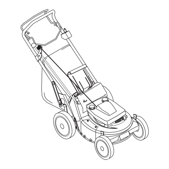
CONTROLS AND FEATURES ENGLISH 1. Engine Control 2. Ignition Switch (Electric Start Models) 3. Speed Selector (Self- propelled) 4. Primer (Briggs Engine) 5. Side Discharge Cover 6. Side Discharge Deflector 7. Cutting Height Levers (2 Rear Wheel Adjusters, 2 Front Wheel Adjusters) 8. -
Page 4: Table Of Contents
OM0400 5. Instruct customer on controls and GB - 4 adjustments have been properly completed. Card and return the card to Husqvarna. Policy. maintenance. Advise customer on adjustments. Remind customer to change oil in 4 cycle engine crankcase after first two (2) hours of operation. -
Page 5: Safety
DISCLAIMER Husqvarna reserves the right to discontinue, make changes to, and add improvements upon its products at any time without public notice or obligation.The descriptions and specifications contained in this manual were in effect at printing. Equipment described within this manual may be optional. Some illustrations may not be applicable to your unit. -
Page 6: Safety Decals And Locations
SAFETY DECALS AND LOCATIONS ALWAYS replace missing or damaged Safety Decals. Refer to Figure 3 for Safety Decal locations. CAUTION • BAG IS SUBJECT TO WEAR AND DETERIORATION. • CHECK BAG FEQUENTLY, REPLACE WHEN NECESSARY. • USE ORIGINAL BAG TO COMPLY WITH SAFETY SPECIFICATIONS. - Page 7 DO NOT pull mower backwards unless absolutely necessary. Look down and back before and while moving backwards. DO NOT start the engine or operate mower unless either the Side Discharge Opening Cover or the Side Discharge Deflector is installed. Keep the area of operation clear of all persons, children and pets.
- Page 8 Accessories Use only accessories which have been approved by Husqvarna and are properly installed. Spark Arrestor This product is equipped with an internal combustion engine. DO NOT use on or near...
-
Page 9: Assembly
TO REMOVE UNIT FROM CARTON 1. Cut off top of carton. 2. Remove front and rear inserts and literature pack. 1. Mower Unit 2. Discharge Chute 3. Grass Bag 4. Grass Bag Frame 5. Literature Pack 6. Battery Charger (electric start models) ASSEMBLY 1. -
Page 10: Operation
CONTROLS AND FEATURES See Figures 1 and 6 for Controls and Features. WARNING: DO NOT attempt to start your engine at this time. Familiarize yourself with controls to see what they do and how they work. Thoroughly read and understand entire Operators Manual first. - Page 11 OPTIONAL CONTROLS See Figures 1 and 6. Cutting Height – Swivel Models CAUTION: On swivel wheel models, when mowing on slopes it is recommended that the linchpin be positioned through the swivel lock hole. If wheels are in the swivel position and control handles are released the mower may “free roll”...
-
Page 12: Filling Fuel Tank
CAUTION: Objects may be thrown. Check grass bag frequently for wear or deterioration. Replace worn or damaged bag with Husqvarna original equipment replacement bag only. Side Discharge: With grass bag removed, remove two lock nuts and washers that secure side discharge opening cover to mower. - Page 13 STARTING AND SHUT OFF See Figures 1, 4 and 6 for all Controls and Features. NOTE: Start engine on a hard level surface that is free of debris. Manual Start 1. Check each item in Before Each Use in the Maintenance Schedule. 2.
-
Page 14: Maintenance
Husqvarna Dealers will provide any service, parts or adjustments which may be required to keep your unit operating at peak efficiency. Should engine service be required, contact a Husqvarna dealer or an authorized engine manufacturer's service center. MAINTENANCE SCHEDULE The chart shows the recommended maintenance schedule that should be performed on a regular basis. -
Page 15: Check Mower Blade
If cutting edge of blade cannot be sharpened in a straight line to within 1/8 of an inch of its end, replace blade with Husqvarna replacement blade only. 4. Install blade, lock washer and cap screw. Blade must be secure and cap screw torqued to 37.5 - 50 ft. -
Page 16: Check Drive Belt
See Adjustments. CHECK GRASS BAG Check bag for wear or damage. Keep bag clean and dry. Replace only with Husqvarna original equipment replacement bag. CHECK DRIVE CONTROL (Self propelled units) Check operation of drive control. The drive must disengage completely when the bail handle is released. - Page 17 Briggs & Stratton Intek OHV 1. Oil Fill Cap & Dipstick 2. Air Cleaner 3. Spark Plug & Wire CHECK ENGINE COOLING Engine is air cooled. Air must circulate freely around engine from Air Intake to cooling fins on cylinder head and block to prevent overheating.
-
Page 18: Service And Adjustments
SERVICE AND ADJUSTMENTS SERVICE POSITION WARNING: ACCIDENTAL ENGINE START UP can cause death or serious injury. ALWAYS stop engine, remove key (electric start models), wait for moving parts to stop and remove wire from spark plug before adjusting or servicing. Place unit on a flat level surface. - Page 19 3. Charge for 24 to 48 hours (battery may be charged for up to 72 hours with no harmful effects). An engine run time of at least 8 hours is required to charge a fully discharged battery. To Remove Battery from Unit 1.
-
Page 20: Speed Control Bell Crank
DRIVE BELT (Self propelled units) To remove drive belt: 1. Position right hand rear wheel Height Adjustment lever in first notch and left hand rear wheel Height Adjustment lever in third notch. This provides clearance between friction wheel and drive disk. 2. -
Page 21: Storage
WARNING: FLAMMABLE FUEL and its EXPLOSIVE VAPORS can cause death or serious injury. DO NOT store unit with fuel in the fuel tank inside a building where any ignition sources are present. Drain fuel outdoors away from any ignition source. Allow engine to cool before storing in any enclosure. -
Page 22: Troubleshooting
5. Friction wheel engagement 6. Idler and idler spring 7. Traction drive cable 8. Bearings damaged. 9. Debris in gear set. ACCESSORIES See your authorized Husqvarna dealer to add these optional accessories. 606 00 00 01 Dethatcher 606 00 00 02 Swivel Wheel... -
Page 23: Specifications
Model Number 601 10 00 24 601 10 00 20 601 10 00 21 601 10 00 22 601 10 00 23 Description Length - in (cm) Height - in (cm) Width - in (cm) Actual Weight - lbs (kg) Cutting Width Cutting Height - in. -
Page 24: Warranty
GB - 24... - Page 25 GB - 25...
- Page 26 01194000A...