
Related Manuals for Smithy GRANITE 1300 SERIES


Summary of Contents for Smithy GRANITE 1300 SERIES
- Page 1 GRANITE 1300 SERIES COMBINATION LATHE/MILL/DRILL OPERATOR’S MANUAL Updated April, 2008 170 Aprill Dr., Ann Arbor, MI, USA 48103 Toll Free 1-800-476-4849 www.smithy.com...
- Page 2 While every precaution has been taken in the preparation of this manual, Smithy Co. shall not have any liability to any person or entity with respect to any loss or damage caused or alleged to be caused directly or indirectly by the instructions contained in this manual.
-
Page 3: Table Of Contents
Items Mounted to your machine ......3-1 Items Packed in the larger Smithy Box ..... . .3-2 Items Packed in smaller Smity Box . - Page 4 Adjusting Lathe Belt Tension .......5-19 Becoming Familiar with Operating Your Smithy Granite ..5-20 Running in the Lathe .
- Page 5 Chapter 7: Manual Operations Overview ..........7-1 Changing Between Lathe and Mill Operation .
- Page 6 Chapter 12: Troubleshooting Powerfeed and Thread Cutting ......12-1 Carriage/Milling Table ........12-2 Lathe Turning .
- Page 7 Appendix A: Machining Reference Guide How to Determine Speeds and Feeds for Lathe Turning ..........A-1 Turning Speed .
-
Page 8: Chapter 1: Introduction
Congratulations on the purchase of your Smithy Granite machine. We welcome you to the Smithy family. Smithy strives to provide you with the best in machine tools. Please read through this manual carefully to ensure that you get the most out of your Granite 3-in-1 lathe-mill-drill. - Page 9 5:00 p.m. Eastern Standard Time. You can also e-mail your questions 24 hours a day to info@smithy.com. Customer Information Please record the information below about your Smithy machine. Having this information readily available will save time if you need to contact Smithy for questions, service, accessories, or replacement parts. Model number:_____________________________________ Serial Number: ____________________________________...
-
Page 10: Chapter 2: Safety
Safety Overview Smithy machines are proven to be safe and reliable; however, if abused or operated improperly, any machine can cause injury. Please read this manual carefully before you start machining. Proper use will create a safe working environment and prolong the life of your machine. -
Page 11: Shop Safety Rules
DANGER Smithy strongly discourages the use of casters or wheels on metal-working machine benches. The weight of the machine could result in the bench tipping while being moved. Once the machine is mounted, consider your workbench to be permanent. If you must... -
Page 12: Machine Safety Rules
12. Keep your machine maintained. Always replace worn or damaged parts before using your machine to prevent damage to your machine or the operator. Follow the maintenance schedule outline in this manual for peak performance. Or Visit www.smithy.com... -
Page 13: Chapter 3: Inventory Check List
By doing so, you can quickly determine if any parts are missing. In addition, should you find it necessary to return the machine to Smithy for any reason, the inventory will ensure that all the parts you received have been returned. -
Page 14: Items Packed In The Larger Smithy Box
3: Inventory Check List Items Packed in the Larger Smithy Box The following items are packed in the larger of the two Smithy boxes. Air Mask End Mill, 4 FL HSS Part # 15-020 1/4” w/3/8” Shank Quantity 1 Part # 50-402... - Page 15 Granite 1300 Series Operator’s Manual Drill Chuck, 13/16 mm Open End JT3, 0.8-16 mm Wrench with key Part # G20131 (for millhead) Quantity 1 Part # 72-003 Quantity 1 10/12 mm Open End Drill Chuck Arbor, Wrench R-8/JT3 Part # G20101...
- Page 16 Rack & Pinion Part # G02034-A710 Or Travel Handle Part# G02034A-1/2” X 30 Part # G08031 Quantity 1 Quantity 2 Items Packed in Smaller Smithy Box Spanner Wrench Outside Jaws for Part # G20001 Lathe Chuck Quantity 1 Part #...
-
Page 17: Items Packed In Plastic Bag
Granite 1300 Series Operator’s Manual Items Packed in Plastic Bag DVD, Machine Operator’s Manual Tool Basics Part # 83-950 Part # 12-003 Quantity 1 Quantity 1 Manual Cover Part # 83-942 Quantity 1 Additional Items for GN-IMX Series Live Center**... -
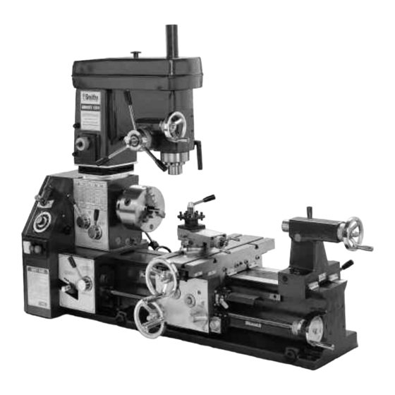
Page 18: Chapter 4: Machine Overview
Machine Overview Overview This chapter will help you to familiarize yourself with the Smithy Granite 1300 models and standard accessories. Figures 4.1 through 4.15 identify the major components and functions of your machine. The photographs in this section depict a Granite 1324 model. - Page 19 Granite 1300 Series Operator’s Manual Millhead Tailstock Carriage Assembly Motor Assembly Figure 4.2 Granite 1324 Back View For Assistance: Call Toll Free 1-800-476-4849...
-
Page 20: Millhead Components And Functions
4: Machine Overview Millhead Components & Functions The photos below show the front and back of the millhead of the Smithy Granite machine. The millhead holds the tooling necessary to perform milling and drilling operations. The following section identifies the components and functions of the millhead. - Page 21 Granite 1300 Series Operator’s Manual G. Drill/Mill Fine Feed Handwheel - The handwheel controls the fine feed movement of the quill in and out of the millhead. H. Height Adjustment Drive - The height adjustment drive works with the millhead crank to raise and lower the millhead.
-
Page 22: Powerhead Components And Functions
Powerhead Components & Functions Figure 4.5 Granite Powerhead Parts (Front View) A. Lathe/Mill Clutch - This clutch engages the mill portion of the Smithy Granite Lathe- Mill-Drill when pulled out and moved to the left. When moved to the right the lathe is engaged. - Page 23 Granite 1300 Series Operator’s Manual Figure 4.6 Granite Powerhead Parts (Back View) A. Oil Fill Port - Located directly above the motor, it holds 8-10 oz of 30 weight oil. Remove the screw to add oil as necessary. B. Belt Tension - Moves the motor pulley up and down releasing tension on the belts.
-
Page 24: Pulley Box
L-8. SCR Module - Converts the AC power coming into the machine to DC power for the motor. L-9. Inch/Metric Selector - Used when cutting threads. Pull the lever out toward the operator when cutting metric threads. When cutting inch (SAE) threads, make sure the lever is pushed in toward the machine. Or Visit www.smithy.com... -
Page 25: Carriage Asssembly
Granite 1300 Series Operator’s Manual ! NOTICE ! There is a neutral position with this selector. Be sure that it is completey engaged in either the metric or inch mode before you begin your threading operation. L-10. Leadscrew Clutch- Is designed to slip to reduce damage to the machine apron if the carriage is accidentally run into the head of the machine. - Page 26 The threading dial can only be used when cutting inch (SAE) threads. G. Saddle - The saddle supports the cross-slide table and moves along the X-Axis of the machine. H. Apron - The apron houses the gear mechanism for the X and Y-Axis powerfeed. Or Visit www.smithy.com...
- Page 27 Granite 1300 Series Operator’s Manual Figure 4.9 Granite Carriage Gib Adjustment Screws (Quantity 4) I. Carriage Gib Adjustment Screws - These screws press a small metal plate (the gib) to the ways of the bed, increasing or decreasing the tension when moving the cross-slide assembly.
-
Page 28: Carriage Assembly-Compound Angle Toolpost
A. CATP (Compound Angle Toolpost) Lock down handle - The handle rotates counterclockwise to loosen the tension on the four position turret, allowing the user to turn the turret 90º per turn. 4-11 Or Visit www.smithy.com... -
Page 29: Tailstock
Granite 1300 Series Operator’s Manual B. Turret Bolts - These bolts secure your tooling to the turret. C. 4 Position Turret - The turret holds up to 1/2” tooling. The turret can support up to 4 tools. D. Compound Slide - The compound slide moves the tooling in towards and away from the workpiece. -
Page 30: For Granite Max And Imx Series Machine
D. Extended Tailstock Travel - Drill or ream deeper with 3” travel, also reach farther across the table with the center securely placed in the tailstock. E. Quick Change Toolpost (For Idustrial MAX Series Only) - The fastest, most convenient way to change a tool. 4-13 Or Visit www.smithy.com... -
Page 31: Chapter 5: Preparing Your Machine For Operation
Preparing Your Machine For Operation Overview The Quick-Start Manual you received before delivery of your Smithy machine provides detailed instructions for mounting and locating your machine. Please complete those instructions if you have not already done so. As you unpack, it is a good idea to inventory the parts. -
Page 32: Arbor Plug
Figure 5.3 Installing Mill Spindle Cover The mill spindle cover slides over the flange on the top of the millhead. WARNING Do not operate your machine without the mill spindle cover. Doing so could cause harm to yourself or your machine. Or Visit www.smithy.com... -
Page 33: Cleaning And Lubricating Your Machine
Cleaning & Lubricating Your Machine Smithy machines are shipped with a light protective grease coating that must be removed prior to use. Use a noncorrosive kerosene or white mineral spirits to remove the coating. WD-40® also works well. -
Page 34: Gearbox
Figure 5.6 The oil level should be half way in the oil site glass located under the lathe spindle. Figure 5.7 Add oil through the oil port located on the back side of the headstock. Or Visit www.smithy.com... -
Page 35: Ways
Granite 1300 Series Operator’s Manual Ways Run the carriage as far to the left as possible. Put a few drops of oil on the ways. Run the carriage to the extreme right and repeat. Carriage Assembly-Saddle Lubricate the four oil buttons of the cross-slide table There are two buttons on both the right (tailstock) side and left side (head stock) of the carriage for the ways. -
Page 36: Carriage Assembly-Cross-Slide Table
There is one button on each side of the cross slide for the cross-slide ways. Figure 5.9 Carriage Assembly Cross Slide Table Points Compound Angle Toolpost Oil the two buttons on the top of the compound rest. Figure 5.10 Oil the Compound Angle Toolpost at its oil points Or Visit www.smithy.com... -
Page 37: Cross-Slide Screw
Granite 1300 Series Operator’s Manual Cross-Slide Screw Oil the cross-slide screw. The first oil button is located on the apron next to the cross- slide dial and the other is found on the top of the cross-slide table. Oil the buttons between the cross-slide and longitudinal-feed handwheels (at right). -
Page 38: Quick Change Gearbox
Tailstock Barrel Oil the two buttons on top of the tailstock. Figure 5.15 Tailstock Barrel Oil Points Mill/Drill Clutch, Fine Feed Oil the button on top of the mill/drill clutch housing. Figure 5.16 Mill/Drill Clutch Oil Points Or Visit www.smithy.com... -
Page 39: Adjusting Gibs
Granite 1300 Series Operator’s Manual Adjusting Gibs The Granite 1300 models have a series of straight gibs. The gibs are found on the carriage, the cross-slide table, compound angle toolpost and the tailstock. These gibs should be adjusted periodically to maintain accuracy and smooth operation. -
Page 40: Carriage Assembly - Cross-Slide Table
Step 6: Once slight resistance is felt, hold the gib adjustment screw in position and tighten the jam nut. Step 7: Repeat steps 5 and 6 with the other inner screw and then with the two outer screws. 5-10 Or Visit www.smithy.com... -
Page 41: Compound Angle Toolpost
Granite 1300 Series Operator’s Manual Adjusting the Gibs on the Compound Angle Toolpost Adjust the gibs on the compound-angle toolpost using the procedure below. Figure 5.19 Gib Adjustment Screws - Compound Angle Toolpost Step 1: Loosen the jam nuts on the side of the compound-angle toolpost with the 6 inch adjustable wrench. -
Page 42: Tailstock
The tailstock will be locked to the ways with the tailstock lock. The objective of adjusting the tailstock is to ensure that the tailstock remains parallel to the ways. 5-12 Or Visit www.smithy.com... -
Page 43: Adjusting Backlash
Granite 1300 Series Operator’s Manual Adjusting Backlash Backlash is lost motion in the screw. The user will notice an initial small movement in the handwheel before the screw responds. The procedures in this section will help minimize backlash. Adjusting Backlash from the Cross-Slide Screw Before making any adjustments to the cross-feed screw system, all the gibs on the table and carriage system should be checked and adjusted as described previously. - Page 44 Adjusting Screws Table view from Saddle rear of machine. Brass Nut Cross-slide table 2 Piece Brass Nut Cross-slide screw Adjusting Screws Locking Bolt Saddle Figure 5.23 Tighten the adjusting screws on the brass nut 5-14 Or Visit www.smithy.com...
-
Page 45: Longitudinal Leadscrew
Granite 1300 Series Operator’s Manual Step 5: Reinstall the rear support and tighten the locking bolt for the brass nut. Step 6: Recheck the backlash on the cross-slide. ! NOTICE ! If you find that the four adjusting screws will not stay in place, use a small amount of thread-locking compound to keep the screws tight. -
Page 46: Half-Nut To Leadscrew Backlash
They are located on top of the vertical feed housing at the left and right end of the worm gear. ! NOTICE ! The bearing housing has two holes in the outside surface to allow a punch or spanner wrench to turn the housing. 5-16 Or Visit www.smithy.com... -
Page 47: Adjusting The Fit Of The Quill Gear To The Quill Rack
Granite 1300 Series Operator’s Manual Setscrews Dial Bearing Housing Handwheel Worm Gear & Shaft (Inside Casting) Drill Press Handles Pinion Gear (Inside Casting) Figure 5.25 Adjusting backlash from the mill feed Step 3: Use a small spanner wrench or a punch with a small mallet to rotate the bearing supports one at a time. - Page 48 Step 5: Using the punch and small hammer, tap the narrow movable gear toward the right. This will make the gear assembly appear to have thicker teeth. Step 6: Tighten the spanner nut with the punch and hammer. 5-18 Or Visit www.smithy.com...
-
Page 49: Adjusting Drive Belt Tension
Granite 1300 Series Operator’s Manual Step 7: With the quill still locked, move the coarse feed handle and check for a reduction in backlash. Step 8: Bend the locking tab back into one of the slots in the spanner nut. -
Page 50: Becoming Familiar With Operating Your Smithy Granite
Once the machine has been lubricated and adjusted and before you begin working, take time to become familiar with the operation of your Smithy machine. Although all Smithy machines are run at the factory, it is wise to put your machine through a break-in run before putting it to work. -
Page 51: Running In The Lathe
Granite 1300 Series Operator’s Manual Running in the Lathe Perform these operations to familiarize yourself with lathe operation. Step 1: Position the carriage and cross-slide table to a mid-range position. Step 2: Keep the lathe/mill clutch in the lathe position from the previous steps. -
Page 52: Running In The Mill/Drill
(Move the handle to the right and up.) Observe the lateral movement of the cross-slide table. Step 9: Move the longitudinal and lateral powerfeed selector to the neutral position. Step 10: Turn the variable speed selector to zero. Step 11: Push the red mushroom stop switch to stop the machine. 5-22 Or Visit www.smithy.com... -
Page 53: Chapter 6: Tooling Installation
This section contains information on installing tooling for your lathe and mill. Setting-up Lathe Tooling There are three main areas to set-up tooling when you are using the lathe portion of your Granite 1300 series tool: •Lathe Spindle •Compound Angle Toolpost •Tailstock... -
Page 54: Removing D1-4 Camlock Tooling From The Lathe Spindle
12 o’clock/unlocked position. Step 2: Align the three mounting studs to the spindle nose and slide the chuck into place. Step 3: With the chuck in position, insert the chuck key provided into each Or Visit www.smithy.com... -
Page 55: Installing Compond Angle Toolpost
Granite 1300 Series Operator’s Manual socket on the spindle flange and rotate each camlock clockwise to the locked position. The indicator hashmark on each camlock socket should be somewhere between the 5 and 6 o’clock position. If the desired rotation on any cam lock cannot be obtained, the mounting studs may need to be adjusted. -
Page 56: Setting-Up Tooling In The Mill/Drill Spindle
Setting-up Tooling in the Mill/Drill Spindle This section will explain tool mounting in the mill/drill spindle. The mill spindle of the Granite 1300 series machines is an R-8 (Bridgeport®) standard. It features a straight shank with a flared nose for centering the tool and a keyway for alignment. -
Page 57: Removing R-8 Tooling From The Drawbar
Granite 1300 Series Operator’s Manual Step 3: Use a wrench to apply torque to the drawbar. This will draw fixture firmly into the spindle. Step 4: Reinstall the spindle cap when the fixture/tooling is in place. Figure 6.5 Use the supplied spanner wrench to hold... - Page 58 Rags loosely thrown in the bottom of the box provide padding for the tool to land in when the drawbar is removed from the fixture and the fixture falls from the mill spindle. NOTES: Or Visit www.smithy.com...
-
Page 59: Chapter 7: Manual Operations
This section contains information on manual machine operations that are specific to the Granite 1300 series machines. General machining practices can be found in one of the many machining reference books that Smithy carries such as the Home Machinist Handbook, item 10-005. Appendix A includes a machining guide. -
Page 60: Manual Feeding
• The spindle coarse feed is used for positioning during setup and for feeding drill-press operations. • The spindle fine feed is used for milling operations and can also be used for drilling where a more precise control of the drill bit may be required. Or Visit www.smithy.com... -
Page 61: Coarse Feed Operation
Granite 1300 Series Operator’s Manual Coarse Feed Operation Figure 7.2 Mill/Drill Press Clutch pulled out, engaging the Drill Press Pull the fine-feed clutch knob outward while slowly rotating the drill press handles back and forth. Once the knob is pulled out, the drill press handles can be used for coarse feeding by rotating the handles clockwise to feed into the workpiece and counter clockwise to feed away from the workpiece. -
Page 62: Carriage Assembly
The longitudinal handwheel is always engaged and movement is measured by the dial behind the handwheel. This feed is typically used for rapid movement of the carriage assembly. Or Visit www.smithy.com... - Page 63 Granite 1300 Series Operator’s Manual Before using the longitudinal fine feed handwheel disengage Selector Lever (1- 7) and the Selector Lever (I-III). Move the half-nut engagement lever to the engaged position (handle pointing down). Turn the leadscrew handwheel to feed the carriage assembly left or right. The movement is measured by the dial on the right end of the leadscrew.
-
Page 64: Chapter 8: Speeds And Feeds
Speeds and Feeds Overview Before using the more advance features of your Granite 1300 Series Lathe-Mill- Drill, it is important to have a basic understanding of feeds and speeds. This section contains information on how to set the speed and feeds rates for your machine. -
Page 65: Setting The Spindle Rotational Speed
Granite 1300 Series Operator’s Manual Setting the Spindle Rotational Speed Once you have determined the proper speed and feed rate for the material that you are cutting and the type of cutter that you will be using, you will need to... -
Page 66: High Range Speed Set-Up
Machines purchased after mid-2003 have the speed reducer pulley installed on the machine. A retrofit kit, part number 40- 300G, to add this feature to earlier machines is available from the Smithy Sales Department at 1-800-476-4849 or at www.smithy.com. High Range-Speed Set-up Use the procedure below to set up for high speed (1500 to 3000 RPM) operations. -
Page 67: Low Range Speed Set-Up
Granite 1300 Series Operator’s Manual High Speed Mid Speed Range Range Motor Motor Figure 8.2 The high & mid-speed ranges only require the use of one belt Low Range-Speed Set-up For low-speeds (optional on early machines), you must convert to a double drive belt configuration. -
Page 68: Feed Chart Explained
Section 1 is headed by the symbol at the left. The meaning is “Do NOT change selector handle positions while the machine is running”. Please stop the machine while changing feed directions, gear selections, feed-rate selections, etc.” Or Visit www.smithy.com... - Page 69 Granite 1300 Series Operator’s Manual Below the symbol is a representation of the feed gears, A, B, C, and D on the gear quadrant. These gears are located inside the pulley box. Immediately to the right of the gear symbols are the numbers 1 through 7, which refer to the position of the powerfeed selection lever (1-7) on the feed transmission.
- Page 70 Section two of the chart list the feed rates for the X-Axis (longitudinal feed). The same gear set-up is required as for cutting inch threads. Section three of the chart list the feed rates for the Y-Axis (lateral feed). The same gear set-up is required as for cutting inch threads. Or Visit www.smithy.com...
-
Page 71: Sample Settings
Granite 1300 Series Operator’s Manual Section four and five of the chart list the metric thread pitches when using the following gear set-up: Section 4 Section 5 A=33 A=66 B=80 B=64 C=63 C=63 D=60 D=60 Changing gears will be covered in the Threading chapter. - Page 72 8: Speeds & Feeds ! NOTICE ! The feed chart on your machine is in millimeters per spindle revolution. Please see Appendix B for feed rates based in inches per spindle revolution. NOTES: Or Visit www.smithy.com...
-
Page 73: Overview
This section will give you step by step instructions for using the powerfeed on your Granite 1300 series lathe-mill-drill. General machining practices can be found in the one of the many machining reference books that Smithy carries such as the Home Machinist Handbook, item 10-005. General Safety Operations... - Page 74 Selector Lever (1-7) and Selector Lever (I-III) as well as the carriage gearing by engaging the powerfeed lever into the proper position. Figure 9.2 Selector Lever (1-7) & Selector Lever (I-III) Or Visit www.smithy.com...
- Page 75 Granite 1300 Series Operator’s Manual The powerfeed engagement lever is located on the upper right side of the apron and has a three-position gate with neutral, longitudinal (x axis) and cross feed (y axis). The powerfeed engagement lever can be operated while the machine is running.
-
Page 76: The Jog Knob
(or the closest to the listed range for your work material cutter.) See section 8 for a detailed chart explanation. Step 4: Position the selector (1-7) into the position listed on the chart for the desired feed rate. Or Visit www.smithy.com... -
Page 77: Step-By-Step Mill Powerfeeding
Granite 1300 Series Operator’s Manual Step 5: Position the selector (I-III) into the position listed on the chart for the desired feed rate. Step 6: Set the recommeded speed for the work stock material and cutter that you are using. (See chapter 8 for setting speeds.) - Page 78 Y-Axis. Pushing the lever down will engage the X-Axis powerfeed.) Step 9: To stop powerfeeding, disengage the powerfeed by moving the lever into the neutral position which is half way between the Y-Axis and X-Axis engagement. Or Visit www.smithy.com...
-
Page 79: Chapter 10: Threading
Threading Overview This section of your manual covers threading operations on your Granite 1300 series lathe-mill-drill. This section will build the information presented in chapters 8 and 9. If you have not read these sections, please do so before continuing. General Safety Operations CAUTION For your own safety and the safety of those around you, follow... -
Page 80: Basic Threading
Step 2: Consult the thread chart on the headstock support column for the thread pitch that you wish to cut. The bottom row of the chart will show you the gear set-up inside the pulley box that is required to cut the desired thread pitch. 10-2 Or Visit www.smithy.com... -
Page 81: Changing Gears
Granite 1300 Series Operator’s Manual Step 3: If changing the gear set-up is necessary to achieve the desired thread pitch, follow the procedure under the title “Changing Gears” in the next section. Changing Gears Step 1: The A gear is secured with a bolt and washer assembly and the location is fixed. -
Page 82: Cutting Inch Threads
Cutting Inch Threads Step 1: Select the desired thread pitch that you wish to cut from the chart located on the headstock of the Granite 1300 series lathe-mill-drill. Step 2: Engage selector levers (1-7) and selector lever (I-III). Remember, you can use the jog knob located on the right side of the gear box to help align the gears if the levers are difficult to engage. -
Page 83: Using The Threading Dial To Cut Inch Threads
Granite 1300 Series Operator’s Manual Figure 10.5 Half Nut Engaged Step 9: When you reach the end of the first cut, lift up on the half-nut engagement lever, back the cutter out using the CATP feed and return the cutter to the starting point. -
Page 84: Cutting Metric Threads
Cutting Metric Threads Step 1: Select the desired thread pitch that you wish to cut from the chart located on the headstock of the Granite 1300 series lathe-mill-drill. Step 2: Engage selector levers (1-7) and selector lever (I-III). Remember, you can use the jog knob located on the right side of the gear box to help align the gears if the levers are difficult to engage. -
Page 85: Chapter 11: Machine Maintenance Schedule
Machine Maintenance Schedule Overview To keep your Smithy Granite machine running at optimum performance, follow this basic maintenance schedule: Before Each Use Make sure your work area is clean and free of all obstructions. Clear machine cross-slide table, bed ways and tool post of all chips built up from your previous job. -
Page 86: Hours (Daily)
Check the condition of all drive belts and replace if necessary. 100 Hours (Yearly) Change oil in the headstock. Remove the X and Y-Axis gibs and clean with solvent. Coat gibs with way oil and reinstall. 11-2 Or Visit www.smithy.com... -
Page 87: Chapter 12: Troubleshooting
Troubleshooting Powerfeed and Thread Cutting 1. Powerfeed does not move carriage Cause Solution • Carriage locked • Unlock carriage • Speed selector not engaged • Select speed I or II or III, engage drive selector • Sheared pin • Replace pin •... -
Page 88: Carriage/Milling Table
• Put a shim between the stud on the nut and the side of the hole • Worn brass nut • Replace brass nut or adjust screw at end of nut • Excessive space between bearing • Add shim washer and dial 12-2 Or Visit www.smithy.com... -
Page 89: Lathe Turning
Granite 1300 Series Operator’s Manual Lathe Turning Cause Solution • Tool dull • Sharpen or replace tool • Tool not ground properly • Regrind tool • Tool at wrong angle • Correct tool position • Tools not held tightly • Tighten toolholder •... -
Page 90: Milling
• Chuck loose in spindle • Remount chuck on arbor • Drawbar not secured • Tighten drawbar • Debris on spindle • Clean debris and arbor and remount tool • Bearing loose or worn • Tighten or replace bearings 12-4 Or Visit www.smithy.com... -
Page 91: Drive System
Granite 1300 Series Operator’s Manual • Cutting too fast • Reduce speeed • Incorrect bit • Use correct bits • No pilot hole • Drill small pilot hole 2. Entrance hole is out of round Cause Solution • Bit dull •... -
Page 92: Motor
Figure 12.1 D1-4 Lathe Chuck in Locked & Unlocked Position 3. Position all three cams in the unlocked position, put your right hand under the chuck for support and tap the chuck with a block of wood to break it loose from the spindle. 12-6 Or Visit www.smithy.com... - Page 93 Granite 1300 Series Operator’s Manual 4. Inspect the mating surfaces on the end of the spindle and the back of the chuck for burrs or foreign matter. Clean and deburr these areas as necessary. Installing and Adjusting the chuck 1. Make sure that the cams are aligned in the unlocked position and slide the chuck onto the spindle.
-
Page 94: Leadscrew
3. Using a punch and a small hammer, tighten the spanner nut about one eigth of a turn and recheck the play in the screw. 4. If the play is acceptable, replace the handle and retaining bolt. If more adjustment is needed, repeat the step above. 12-8 Or Visit www.smithy.com... - Page 95 Granite 1300 Series Operator’s Manual Spanner Nut Handwheel Lead Screw & Dial Mounting Trestle Retaining Bolt & Washer Figure 12.4 Parts of the Handwheel Half nut to screw backlash Worn threads on the half nut can cause excessive backlash in the longitudinal direction.
- Page 96 3. Crank the crossfeed table toward the operator side of the machine. Watch under the table from the backside and stop before the crossfeed screw comes out of the brass nut. Cross-slide table 2 Piece Brass Nut Cross-slide screw Adjusting Screws Locking Bolt Saddle Figure 12.6 Crossfeed Table Cross Section 12-10 Or Visit www.smithy.com...
-
Page 97: Granite Series Leadscrew Handwheel
Granite 1300 Series Operator’s Manual Adjusting Screws Table view from rear of Saddle machine. Brass Nut Figure 12.7 Crossfeed Table Rear View Cross Section 4. Slowly tighten the four adjusting screws on the brass nut, one at a time, until a slight drag is felt while turning the crossfeed handle. - Page 98 Drill the hole about 5/8 inch deep. Tap the hole with the 5/16 tap. Do not forget to use oil when drilling and tapping. NOTES: 12-12 Or Visit www.smithy.com...
-
Page 99: Chapter 13: Machine Specifications
Machine Specifications Granite 1324 Series Machine General Specifications General Dimension: 39” height X 46” length X 22-1/2” width Machine Weight: Shipping 770 lbs, Machine 661 lbs Crate Size: 49-1/2” X 22-3/4” X 44” Footprint (static): 48” X 36” Footprint (operating): 72-1/2”... - Page 100 220 Volts A/C Phase: Single Recommended Oil for Lubricant For Gear Box: SAE30 weight non-detergent oil or 30 weight compressor oil For External : Regular Oil For Cleaning: Noncorrosive Kerosene or White Mineral Spirits or even WD-40 13-2 Or Visit www.smithy.com...
- Page 101 Granite 1300 Series Operator’s Manual Granite 1340 Series Machine General Specifications General Dimention: 39” height X 62” length X 22-1/2” width Machine Weight: Shipping 910 lbs, Machine 728 lbs Crate Size: 64-1/2” X 22-3/4” X 44” Footprint (static): 64” X 36”...
- Page 102 GN-MAX & GN-IMX: 2.0 HP Motor Type: GN Classic: D/C Variable Speed (Permanent Magnet) GN-MAX & GN-IMX: D/C Variable Speed (Brushless Servo) Voltage: GN Classic & GN-MAX: 110 Volts A/C GN-IMAX: 220 Volts A/C Phase: Single 13-4 Or Visit www.smithy.com...
-
Page 103: Appendix A: Machining Reference Guide
(fpm) cutting speed. Lathes cut threads in various numbers per inch of materials threaded, according to the operator's needs. The Smithy Granite Series machine cuts threads to metric or inch standards. In thread cutting, the carriage carries the thread-cutting tool and moves by the rotating leadscrew. - Page 104 Granite 1300 Series Operator’s Manual The lathe spindle holding the workpiece revolves at a selected speed (revolution per minute, or rpm) according to the type and size of the workpiece. The leadscrew, which runs the length of the lathe bed, also revolves at the desired rpm. There is a definite and changeable ration between spindle and leadscrew speeds.
-
Page 105: Cutting Speed And Feed For High Speed Steel Tools
Cutting Speeds and Feeds for High Speed Steel Tools High- Low-Carbon Carbon Alloy Steel Aluminum Cast Iron Bronze Steel Steel Normalized Alloys Annealed Speed (sfm) Roughing Finishing Feed (ipr) 0.010-0.202 1.101-0.020 0.010-0.020 0.015-0.030 0.010-0.020 0.010-0.020 Roughing 0.003-0.005 0.003-0.005 0.003-0.005 0.005-0.010 0.003-0.010 0.003-0.10 Finishing Or Visit www.smithy.com... - Page 106 1/2” or smaller shanks. The centerline is approximately 5/8” above the bottom of the turret. Smithy also offers quick- change tool sets that greatly speed up lathe operations. Contact a Smithy technician for details.
-
Page 107: How To Determine Speeds And Feeds For Milling
Set the direction of feed before you begin milling. Up milling, or conventional milling, is when the direction of feed is opposite to the direction of cutter rotation. Down milling, or climb milling, is when the direction of feed is the same as the direction of cutter rotation. Or Visit www.smithy.com... -
Page 108: Up Milling
Granite 1300 Series Operator’s Manual Up Milling In up milling, forces on the workpiece tend to pull it out of the vise or fixture holding it, so fasten it securely. These forces also push the workpiece away from the cutter, which eliminates backlash. - Page 109 4. grind the end clearance 5. grind the top rake, touching in a chipbreaker. If you are honing the cutting edge (for fine finishing or machining soft materials), draw the cutter away from the cutting edge across the oilstone (Figure A.4). Or Visit www.smithy.com...
-
Page 110: Materials Other Than Steel
Granite 1300 Series Operator’s Manual Cutter Bit Grinding Wheel 1. Left Side 2. Rigt Side 3. End 4. Radius 5. Top Rake Clearance Clearance Clearance Figure A.3 Grinding sequence for an unground cutter bit Oilstone Figure A.4 When honing, draw the cutter away... -
Page 111: Bits For Turning And Machining Brass
V in a standard center gauge (Figure A.8) Examine the gauge and cutter above a light. When the cutter is ground perfectly, no light streak shows between the tool and gauge. Use a grinding chart for other rakes. Or Visit www.smithy.com... -
Page 112: Acme Or Other Special Threads
Granite 1300 Series Operator’s Manual Figure A.8 Insert the point into the nearest-sized V in the center gauge Acme or Other Special Thread Thread gauge are available for all standard threads. Before grinding such cutters, ascertain the correct pitch angle of the particular thread profile. For example, the pitch of an acme thread is 29°... -
Page 113: Endmill Cutters
Teeth may be on one end (single-ended) or both ends (double-ended). • Multiple-flute endmills have three, four, six, or eight flutes and may be single or double-ended. Multiple-flute mills are center-cutting or non-center cutting. Don't use noncenter-cutting endmills for plunge milling. A-11 Or Visit www.smithy.com... -
Page 114: Plain Milling Cutters
Granite 1300 Series Operator’s Manual • Geometry-forming endmills form particular geometries. They include ball endmills, roughing endmills, dovetail endmills, T-slot cutters, keyseat cutters, and shell endmills. • Ball endmills cut slots or fillets with a radius bottom, round out pockets and bottoms of holes, and do diesinking and diemaking. -
Page 115: Side Milling Cutters
• Single-angle cutters have one angular surface. Teeth are on the angular surface and the straight side, and they usually have 45° or 60° angles. • Double-angle cutters machine V-grooves. Those with equal angles on both faces usually have an included angle of 45°, 60°, or 90°. A-13 Or Visit www.smithy.com... -
Page 116: Form-Relieved Cutters
Before attempting to cut a thread on a workpiece, cut a few practice threads on odd bits of steel, iron, and aluminum. Built for thread cutting, the Smithy Granite Series machine, cuts standard internal and external threads, as well as special threads. You may cut coarse or fine threads in a great range of threads per inch, in V or square shapes, in established profiles like Unified National, acme, and metric. - Page 117 Screw threads are usually referred to by pitch numbers, such as 18 or 24, meaning 18 or 24 threads per inch (tpi). The Smithy Granite Series machine cuts standard threads in pitches from 7 to 52 tpi and metric threads from 0.35 to 6.5 mm.
-
Page 118: Cutting Right-Hand Threads
Granite 1300 Series Operator’s Manual Before Tool After Figure A.10 Chamfer the end of the thread to protect it from damage Cutting Right-hand Threads Now you are ready to cut right-hand threads. First, advance the tool so it just touches the workpiece and turn the compound calibration to zero. -
Page 119: Cutting Left-Hand Threads
Before cutting an internal thread, bore the workpiece to the exact inside diameter. A-17 Or Visit www.smithy.com... -
Page 120: Cutting Threads On A Taper
Granite 1300 Series Operator’s Manual Because the feed of successive cuts is toward, not away from the operator, the thread-cutting set is reversed. Also, you must take lighter cuts because of the cutter's extension from the toolpost. Take an extra finishing cut without changing the setting of the compound rest. -
Page 121: Appendix B: Inch Feed Rates
C = 60 D = 60 Selection B = 64 D = 60 B = 80 D Lever located I N C H M E T R I C INCH inside Pully Box METRIC below gear cluster Or Visit www.smithy.com... -
Page 122: Machine Warranty
Machine Warranty 30 Day Trial Offer Try a Smithy for 30 days. If, for any reason within that time, you decide to return your Smithy, just call our Customer Service department at 1-800-476-4849. We will help you arrange shipping back to us. When we receive the machine back, we’ll refund your full purchase price. - Page 123 This is Smithy Co.’s sole warranty and any and all warranties that may be implied by law, including any merchantability or fitness, for any particular purpose, are hereby limited to the duration of this written warranty.