Motorola ASTRO XTS 5000 III User Manual
Digital portable radio
Hide thumbs
Also See for ASTRO XTS 5000 III:
- Basic service manual (109 pages) ,
- User manual (134 pages) ,
- User manual (144 pages)
Table of Contents
Advertisement
Quick Links
Advertisement
Table of Contents

Related Manuals for Motorola ASTRO XTS 5000 III


Summary of Contents for Motorola ASTRO XTS 5000 III
- Page 1 ASTRO 5000 ® Digital Portable Radio Model III User Guide...
- Page 3 RF energy awareness information and operating instructions in the Product Safety and RF Exposure booklet enclosed with your radio Press and hold PTT. Announce your (Motorola Publication part number 68P81095C98) to ensure emergency into the microphone. compliance with RF energy exposure limits.
-
Page 4: Menu Entries
Display Status Symbols Menu Entries (Use With Menu Navigation) Entry Menu Selection Page Receiving an individual call Entry Menu Selection Page Call Alert Page PAGE Smart Battery BATT The radio is in the view or program mode; Phone PHON On Steady = view mode; Blinking = Private Call/Selective Call 61/65 CALL... -
Page 5: Declaration Of Conformity
FCC logo shown below. DECLARATION OF CONFORMITY Per FCC CFR 47 Part 2 Section 2.1077(a) Responsible Party Name: Motorola, Inc. Address: 1301 E. Algonquin Rd, Schaumburg, IL 60196-1078 USA Phone Number: 1-800-927-2744 Hereby declares that the product: Model Name: XTS 5000 conforms to the following regulations: FCC Part 15, subpart B, section 15.107(a), 15.107(d) and section 15.109(a) -
Page 6: Computer Software Copyrights
No duplication or distribution of this document or any portion thereof shall take place without the express written permission of Motorola. No part of this manual may be reproduced, distributed, or transmitted in any form or by any means, electronic or mechanical, for any purpose without the express written permission of Motorola. - Page 7 Notes...
-
Page 8: Table Of Contents
Contents General Radio Operation ..... . . 1 Notations Used in This Manual ............1 Your XTS 5000 Model III Radio ............2 Physical Features of the XTS 5000 Model III Radio ...... - Page 9 Contents ARS User Login and Text Messaging Features . . . 105 Automatic Registration Service (ARS) ...........105 ARS User Login Feature ...............107 Text Messaging ................113 Helpful Tips ....... . 127 Radio Care ..................127 Service ...................129 Battery ...................130...
-
Page 10: General Radio Operation
General Radio Operation Notations Used in This Manual Throughout the text in this publication, you will notice the use of WARNING, Caution, and Note. These notations are used to emphasize that safety hazards exist, and the care that must be taken or observed. -
Page 11: Your Xts 5000 Model Iii Radio
General Radio Operation Your XTS 5000 Model III Radio MAEPF-27193-A... -
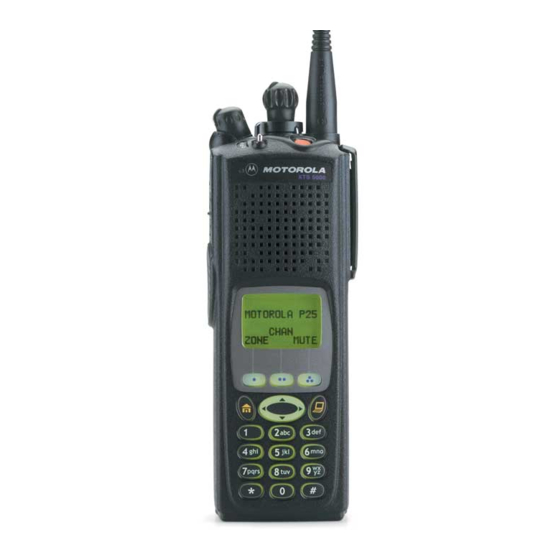
Page 12: Physical Features Of The Xts 5000 Model Iii Radio
General Radio Operation Physical Features of the XTS 5000 Model III Radio Table 1: Physical Features No. Feature Page No. Feature Page 1 Antenna 8 Home Button 2 On/Off/Volume Control 9 Battery Knob 3 LED 10 Keypad 4 Microphone 11 App Button 5 PTT (Push-to-Talk) 12 Display Button... -
Page 13: Display
General Radio Operation Table 2: Programmable Features Feature Page Feature Page Feature Page Call Alert PL Defeat Site Search Call Response Private Call Smart Battery Channel Repeater/Direct Status Dynamic Priority Reprogram Text Messaging Request Emergency Scan List TMS Quick Text Programming Keypad Mute Scan On/Off... -
Page 14: Status Symbols
General Radio Operation Backlight If poor light conditions make the display, keypad, or channel numbers (around the 16-Position Select knob) difficult to read, turn on the radio’s backlights by pressing the preprogrammed Light button. These lights will remain on for a preprogrammed time before they turn off automatically, or you can turn them off immediately by pressing the Light button again. - Page 15 General Radio Operation Table 3: Status Symbols (Continued) Symbol Indication Page No. Talkaround • On = you are talking directly to another radio, not through a repeater, during conventional operation only • Off = you are talking through a repeater Monitor (Carrier Squelch) 28, 35, The selected channel is being monitored...
-
Page 16: Menu Select Buttons
General Radio Operation Table 3: Status Symbols (Continued) Symbol Indication Page No. User Login Indicator (IP Packet Data) • On (Tinted) = User is currently associated with the radio; • Off (Not tinted) = User is currently not 110-110 associated with the radio; •... -
Page 17: Page No. Feature
General Radio Operation Menu Entry Features Table 4: Menu Entries Menu Menu Feature Page Feature Page Entry Entry Smart Battery Phone BATT PHON Private Call / 61/65 Editing CALL PROG Selective Call Channel Selection Password CHAN PSWD Time/Date TX Power Level CLCK Repeater/Direct Rekey Request... -
Page 18: Keypad
General Radio Operation App Button (TMS Feature Button) This button brings you to the Text Messaging Service (TMS) feature screen. 4-Way Navigation Button This button is used to scroll through the radio’s lists or items in the display, or both. Keypad The 3 x 4-key alphanumeric keypad provides an interface to your radio’s... -
Page 19: Led Indicators
General Radio Operation Table 5: Keypad Characters (Continued) Number of times the key is pressed LED Indicators The LED on top of the radio indicates the radio’s operating status: Table 6: LED Indicators LED Indicator What it Means Radio transmitting Blinking red •... -
Page 20: Alert Tones
General Radio Operation Alert Tones An alert tone is a sound or group of sounds. Your radio uses alert tones to inform you of your radio’s conditions. The following table lists these tones and when they occur. Table 7: Alert Tones You Hear Tone Name Heard... - Page 21 General Radio Operation Table 7: Alert Tones (Continued) You Hear Tone Name Heard Valid Key- when correct key is pressed Press Radio Self-Test when radio passes its power-up Pass self test Clear Voice at beginning of a non-coded Short, communication Medium- Priority when activity on a priority channel...
- Page 22 General Radio Operation Table 7: Alert Tones (Continued) You Hear Tone Name Heard Short, GPS RSM Low when this accessory battery is Medium- Battery Chirp below preset threshold value Pitched Tone (Chirp) Fast Ringing when system is searching for target of Private Call Enhanced Call when waiting for target of Private...
-
Page 23: Standard Accessories
Prior to using a new battery, charge it for a minimum of 16 hours to ensure optimum capacity and performance. For a list of Motorola-authorized batteries available for use with your XTS 5000 radio, see “Batteries and Battery Accessories” on page 135. - Page 24 General Radio Operation Attach the Battery With the radio turned off, insert the top edge of the battery into the radio’s frame as shown. Rotate the battery toward the radio and press down until the battery clicks into place. Remove the Battery With the radio turned off, press the release button on the bottom of the battery until...
-
Page 25: Smart Battery Status
General Radio Operation Smart Battery Status This feature lets you view the status of your Smart Battery. Use the Menu Press U to find BATT. BATT Press D, E, or F directly CAPACITY below BATT. INIT 10/01 EST CHGS Note: If a Smart Battery is not SMART BATT powering your radio: DATA NOT... - Page 26 General Radio Operation Antenna For information regarding available antennas, see page 133. Attach the Antenna With the radio turned off, turn the antenna clockwise to attach it to the radio. Remove the Antenna With the radio turned off, turn the antenna counter-clockwise to remove it from the radio.
-
Page 27: Belt Clip
General Radio Operation Belt Clip Attach the Belt Clip Align the grooves of the belt Grooves clip with those of the battery. Slots Battery Battery Press the belt clip downward until you clear a click. Slots Battery Battery Remove the Belt Clip Use a flat-bladed object to press the belt clip tab away Metal... -
Page 28: Universal Connector Cover
General Radio Operation Universal Connector Cover The universal connector is located on the antenna side of the radio. It is used to connect accessories to the radio. Note: To prevent damage to the connector, shield it with the connector cover when not in use. Remove the Universal Connector Cover Insert a flat-bladed screwdriver into the area... -
Page 29: Radio On And Off
General Radio Operation Radio On and Off Turn the Radio On Turn the On/Off/Volume Control knob clockwise. Note: If the power-up test is SELF TEST successful, you briefly see SELF TEST, then the home display. If the power-up test is ERROR XX/YY unsuccessful, you see ERROR XX/YY. -
Page 30: Zones And Channels
General Radio Operation Zones and Channels A zone is a grouping of channels. A channel is a group of radio characteristics, such as transmit/receive frequency pairs. Before you use your radio to receive or send messages, you should select the zone and channel. Select a Zone Use the Menu Entry ZONE Press U to find ZONE. - Page 31 General Radio Operation Use the Menu Entry ZNUP or ZNDN Press U to find ZNUP and ZNUP ZNDN ZNDN. Press and hold D, E, or DISP NW F directly below ZNUP or ZNDN until the zone you want appears. Note: Positions of ZNUP and ZNDN on the display may differ each time you release D, E, or...
-
Page 32: Select A Channel
General Radio Operation Select a Channel Consult a qualified radio technician for the right choice between the following methods: Use the Preprogrammed 16-Position Select Knob After the zone you want is Select displayed, turn the Channel 16-Position Select knob to the desired channel. - Page 33 General Radio Operation Press h to confirm the DISP SE displayed zone and channel. Press the PTT button to transmit on the displayed zone/channel. CHUP or CHDN Use the Menu Entry Press U to find CHUP and CHUP CHDN CHDN. Press and hold D, E, or DISP SE F directly below CHUP or...
-
Page 34: Mode Select Button
General Radio Operation Mode Select Button This feature lets you program the current zone and channel to a Mode Select button with a long press on the Mode Select button. After the buttons are programmed, you can return to the pre- programmed zone and channel with a short press on the programmed Mode Select button. -
Page 35: Receive / Transmit
General Radio Operation Receive / Transmit Radio users who switch from analog to digital radios often assume that the lack of static on a digital channel is an indication that the radio is not working properly. This is not the case. Digital technology quiets the transmission by removing the “noise”... -
Page 36: Use The Preprogrammed Monitor Button
General Radio Operation Adjust the Volume Control knob if necessary. Adjust Level Release the Volume Set button. Press and hold the PTT button to transmit. The LED lights RED while transmitting. Release the PTT button to receive (listen). Use the Preprogrammed Monitor Button Turn the radio on and select the desired zone and channel. -
Page 37: Conventional Mode Operation
General Radio Operation Conventional Mode Operation Your radio may be programmed to receive Private-Line® (PL) calls. Momentarily press the Monitor button to listen for activity. The Carrier Squelch indicator is displayed. Press and hold the Monitor button to set continuous monitor operation. -
Page 38: Common Radio Features
Common Radio Features Selectable Power Level This feature lets you select the power level at which your radio will transmit. The radio will always turn on to the default setting. This feature must be preprogrammed by a qualified radio technician. •... -
Page 39: Use The Preprogrammed Transmit Power Level Switch
Common Radio Features Use the Preprogrammed Transmit Power Level Switch Move the TX Power Level switch to the Low Power position. The power level is set to Low. Move the TX Power Level switch to the HIgh Power position. The power level is set to High. -
Page 40: Radio Lock
Common Radio Features Radio Lock This feature changes your radio to a more robust security system that protects the use of the secure encryption keys. If this feature is enabled in your radio by a qualified radio technician, when you turn the radio on, you see RADIO LOCKED. -
Page 41: Change Your Password
Common Radio Features Change Your Password Press U to find PSWD. PSWD Press D, E, or F directly OLD PASSWORD below PSWD. Enter the old password. -------- Press D, E, or F directly NEW PASSWORD below SEL. Enter the new password. -------- Press D, E, or F directly below SEL. - Page 42 Common Radio Features Enable or Disable the Radio Lock Feature (Secure Radios Only) This feature (programmable by a qualified radio technician) allows you to enable or disable the radio lock feature. Press U to find LOGF. LOGF Press D, E, or F directly PSWD ENABLD below LOGF.
-
Page 43: Mute Or Unmute Keypad Tones
Common Radio Features Mute or Unmute Keypad Tones You can turn the keypad tones on or off. Use the Menu Press U to find MUTE. MUTE Press D, E, or F TONES OFF directly below MUTE. The current state is shown. TONES ON Press D, E, or F directly below OFF or ON. -
Page 44: Conventional Squelch Operation
Common Radio Features Conventional Squelch Operation Analog Options Tone Private Line (PL), Digital Private-Line (DPL), and carrier squelch can be available (preprogrammed) per channel. When in This condition occurs Carrier squelch (C) You hear all traffic on a channel. PL or DPL The radio responds only to your messages. -
Page 45: Pl Defeat
Common Radio Features PL Defeat With this feature, you can override any coded squelch (DPL or PL) that might be preprogrammed to a channel. Place the preprogrammed PL Defeat switch in the PL Defeat position. You can now hear any activity on the channel. -
Page 46: Time-Out Timer
Common Radio Features Time-out Timer The time-out timer turns off your radio’s transmitter. The timer is set for 60 seconds at the factory, but it can be programmed from 0 to 7.75 minutes (465 seconds) by a qualified radio technician. Hold down the PTT button •... -
Page 47: Emergency
Common Radio Features Emergency If the top (orange) button is programmed to send an emergency signal, then this signal overrides any other communication over the selected channel. Your radio can be programmed for the following: • Emergency Alarm • Emergency Call •... -
Page 48: Send An Emergency Call
Common Radio Features When you receive the ACK RECEIVED dispatcher’s acknowledgment, you see • Four tones ACK RECEIVED, four tones • Alarm ends sound, the alarm ends, and • Radio exits emergency the radio exits the emergency mode. If no acknowledgement is NO ACKNOWLDG received, you see NO ACKNOWLDG, the alarm ends,... -
Page 49: Send A Silent Emergency Alarm
Common Radio Features With your radio turned on, EMERGENCY press the Emergency button.The current zone/ • Short tone channel is displayed alternately with EMERGENCY, and a short, medium-pitched tone sounds. Note: To exit emergency at any time, press and hold the Emergency button for about a second. - Page 50 Common Radio Features The silent emergency state • Press and hold Emergency button continues until you: Press and hold the Emergency button for about • Press and release the PTT a second to exit the button emergency state. Press and release the PTT button to exit silent emergency and enter regular dispatch or emergency call.
-
Page 51: Lists
Common Radio Features Lists You can use lists to store frequently used numbers and associate them with names. There are four list types: • Call • Page • Phone • Scan View a List Press U to find VIEW. VIEW Press D, E, or F directly below VIEW. - Page 52 Common Radio Features Edit a Call, Page, or Phone List Number Use the Menu Press U to find PROG. PROG Press D, E, or F CALL directly below PROG. You see PAGE PHON the lists that can be changed. Press D, E, or F FIRE CHIEF p directly below the name of the 701234...
- Page 53 Common Radio Features Press D, E, or F directly below SAVE to save your change. Return to step 4 to make more changes. Press h to return to the home display. Edit a Call, Page, or Phone List Name Use the Menu Press U to find PROG.
-
Page 54: Edit A Scan List
Common Radio Features Press D, E, or F GUARD_ p directly below NAME. The 704444 blinking cursor shows the SAVE location of the character to be added. Press V to erase characters. (If you erase the 704444 entire name and press V or SAVE U, you exit editing without saving your changes.) Press... - Page 55 Common Radio Features Press D, E, or F FIRE DISP NW p directly below SCAN. You see the first list member. p (blinking) indicates the programming mode. Press V or U to find the member you want to change. Press D, E, or F directly below SEL or DEL or RCL.
- Page 56 Common Radio Features Press V or U to select more channels to be added or deleted. Use the keypad to go directly to additional channels to be added or deleted. Use the 16-Position Select knob to select additional channels to be added or deleted.
- Page 57 Common Radio Features Press the Select button once or no icon to add the currently displayed channel to the scan list. AND/OR Press the Select button one or more times to change the scan list status symbol of the currently displayed channel. Note: The maximum number of members for a trunking priority monitor scan list is 15;...
- Page 58 Common Radio Features Press h to exit scan list programming and return to the home display. Use the Preprogrammed Scan List Programming Switch and the Menu Move the Scan List FIRE DISP NW p Programming switch to the Programming position. You see the first list member.
- Page 59 Common Radio Features = this channel is in the scan list as a non-priority channel. = this channel is in the scan list as the Priority 2 channel. (dot blinking) = this channel is in the scan list as the Priority 1 channel.
- Page 60 Common Radio Features Press V or U to find the member you want to change. Press the Select button once or no icon to add the currently displayed channel to the scan list. AND/OR Press the Select button one or more times to change the scan list status symbol of the currently displayed channel.
- Page 61 Common Radio Features You can use the 16-Position Select knob to select another scan list member. Move the Scan List Programming switch out of the Programming position.
-
Page 62: Scan
Common Radio Features Scan The scan feature allows you to monitor traffic on different channels by scanning a preprogrammed list of channels. Your radio can have up to 32 different scan lists. These lists must be preprogrammed by a qualified radio technician. •... -
Page 63: Delete A Nuisance Channel
Common Radio Features Delete a Nuisance Channel When the radio scans to a channel that you do not wish to hear (nuisance channel), you can temporarily delete the channel from the scan list. When the radio is locked onto the channel to be deleted, press the preprogrammed Nuisance Delete button. -
Page 64: Conventional Scan Only
Common Radio Features Conventional Scan Only Make a Dynamic Priority Change While the radio is scanning, the dynamic priority change feature lets you temporarily change any channel in a scan list (except the Priority 1 channel) to the Priority 2 channel. The replaced Priority 2 channel becomes a non-priority channel. -
Page 65: Telephone Calls (Trunking Only)
Common Radio Features Telephone Calls (Trunking Only) Use your radio to make calls similar to standard phone calls. A landline phone can be used to call a radio, or a radio can be used to call a landline phone. Quick Access (One-Touch) If your radio is preprogrammed for Quick Access (One-Touch) Phone Call, you can make a call to one preprogrammed phone number without having to select the feature or a phone number. -
Page 66: Answer A Phone Call
Common Radio Features Answer a Phone Call Use the preprogrammed Call Response button to answer a call. When a phone call is • Telephone-type ringing received, you hear a • Blinking GREEN LED telephone-type ringing, the PHONE CALL LED blinks GREEN, the call received symbol ( ) blinks, and PHONE CALL is displayed. -
Page 67: Select A Phone Number
Common Radio Features Select a Phone Number Use the Menu Press U to find the phone POLICE number you want. 555 8523 LNUM Note: Press LNUM to go to the last number dialed. Go to “Make a Phone Call”, below. Use the Keypad Use the keypad to enter the POLICE... - Page 68 Common Radio Features Table 8: Phone Call Display and Alert Prompts When you press the PTT button NO PHONE and the phone system is not available, you hear a long tone. • A long tone Press h to hang up. The radio returns to the home display.
-
Page 69: Private Calls (Trunking Only)
Common Radio Features Private Calls (Trunking Only) These one-to-one calls between two radios are not heard by others in the current talkgroup. The calling radio automatically verifies that the receiving radio is active on the system and can display the caller’s ID. Quick Access (One-Touch) If your radio is preprogrammed for Quick Access (One-Touch) Private Call, you can make a call to one preprogrammed ID number without... -
Page 70: Answer A Private Call
Common Radio Features Answer a Private Call Use the preprogrammed Call Response button to answer a call. When a Private Call is • Two tones received, you hear two alert • Blinking GREEN LED tones, the LED blinks CALL RECEIVD GREEN, the call received symbol ( ) blinks, and CALL... -
Page 71: Select An Id Number
Common Radio Features Go to “Select an ID Number”, • Use the Menu below. • Use the Keypad Go to “Make a Private Call” on page 63. Select an ID Number Use the Menu Press U to find the ID FIRE CHIEF number you want. -
Page 72: Make A Private Call
Common Radio Features Make a Private Call Press the PTT button to start the Private Call. The called ID is momentarily FIRE CHIEF displayed, then you see ID: 701234 PLEASE WAIT. PLEASE WAIT When you are connected, you FIRE CHIEF see the called ID. -
Page 73: Selective Calls (Astro Conventional Only)
Common Radio Features Selective Calls (ASTRO Conventional Only) A Selective Call is used to call a select individual. It is intended to provide privacy and to eliminate the annoyance of having to listen to conversations that are of no interest to you. Quick Access (One-Touch) If your radio is preprogrammed for Quick Access (One-Touch) Selective Call, you can make a call to one preprogrammed ID number... -
Page 74: Initiate A Selective Call
Common Radio Features Press h to hang up and return to the home display. Initiate a Selective Call Press U to find CALL. CALL Press D, E, or F ID: 702345 directly below CALL. You see LIST the last transmitted or received ID number. -
Page 75: Make A Selective Call
Common Radio Features Use the Keypad Use the keypad to enter the FIRE CHIEF ID number you want. ID: 701234 LNUM Note: Press LNUM to go to the last number dialed. Go to “Make a Selective Call”, below. Make a Selective Call Press the PTT button to start the Selective Call. -
Page 76: Call Alert Paging
Common Radio Features Call Alert Paging Call Alert allows your radio to work like a pager. Even if other users are away from their radios, or if they are unable to hear their radios, you can still send them a Call Alert page. You can also verify if a radio is active on the system. -
Page 77: Answer A Call Alert Page
Common Radio Features Press h or the Call Response button to hang up and return to the home display. Answer a Call Alert Page When a Call Alert page is • Four repeating alert tones received, you hear four • Blinking GREEN LED repeating alert tones, the PAGE RECEIVD... -
Page 78: Initiate A Call Alert Page
Common Radio Features Initiate a Call Alert Page Press U to find PAGE. PAGE Press D, E, or F FIRE CHIEF directly below PAGE. ID: 701234 LIST If an individual Call Alert page was last transmitted or received, you see the individual ID number. -
Page 79: Send A Call Alert Page
Common Radio Features Select an ID Number Use the Menu Press U to find the ID FIRE CHIEF number you want. ID: 701234 LNUM Note: Press LNUM to go to the last number dialed. Go to “Send a Call Alert Page”, below. - Page 80 Common Radio Features If an individual Call Alert NO ACKNOWLDG page is not acknowledged, you see NO ACKNOWLDG. If a group Call Alert page is not acknowledged, you do not see NO ACKNOWLDG. The radio will merely exit Call Alert and return to normal operation.
-
Page 81: Conventional Talkgroup Calls (Conventional Operation Only)
Common Radio Features Conventional Talkgroup Calls (Conventional Operation Only) Talkgroup Call lets you define a group of conventional system users so that they can share the use of a conventional channel. Encryption keys are slaved to talkgroups. When talkgroups are enabled, encryption keys are changed by changing the active talkgroup. - Page 82 Common Radio Features If the encryption key that is ILLEGAL KEY slaved to the new talkgroup is not allowed, you see ILLEGAL KEY and hear a • Momentary key fail tone momentary key fail tone. Press h or the PTT button, or turn the 16-Position Select knob to exit.
-
Page 83: Status Calls (Astro 25 Trunking Only)
Common Radio Features Status Calls (ASTRO 25 Trunking Only) You can send data calls to the dispatcher about a predefined status. Each status can have up to a 12-character name. A maximum of eight status conditions is possible. Send a Status Call Use the Menu Press U to find STS. - Page 84 Common Radio Features Note: No traffic is heard on trunked channels while Status Calls is selected. If the radio detects no Status Call activity for six seconds, an alert tone sounds until h or the PTT button is pressed. Use the Preprogrammed Status Button Press the Status button.
-
Page 85: Repeater Or Direct Operation
Common Radio Features Repeater or Direct Operation Also known as “talkaround operation,” DIRECT lets you bypass the repeater and connect directly to another radio. The transmit and receive frequencies are the same. REPEATER operation increases radio’s range by connecting with other radios through a repeater. - Page 86 Common Radio Features Use the Preprogrammed Repeater/Direct Switch Place the Repeater/Direct switch in either the Repeater or the Direct position. If DIR is selected, the display shows ASTRO XTS 5000 Model III...
-
Page 87: Smart Ptt (Conventional Only)
Common Radio Features Smart PTT (Conventional Only) Smart PTT is a per-channel, programmable feature used in conventional radio systems to keep radio users from talking over other radio conversations. When smart PTT is enabled in your radio, you will not be able to transmit on an active channel. -
Page 88: Special Radio Features
Secure radio operation provides the highest commercially available level of voice security on both trunked and conventional channels. Unlike other forms of security, Motorola digital encryption provides signaling that makes it virtually impossible for others to decode any part of an encrypted message. -
Page 89: Managing Encryption
Special Radio Features Managing Encryption Key Loading Refer to the key-variable loader (KVL) manual for equipment connections and setup. Attach the KVL to your radio. KEYLOADING When it is attached, the display will show KEYLOADING, and all other radio functions, except for power down, backlight, and volume, will be locked out. - Page 90 Special Radio Features such as dynamic regrouping, failsoft, or emergency talkgroup. You can have operator-selectable key erasure. Key Selection Press U until KEY appears on the display. Press D, E, or F HW KEY 1 directly below KEY. The PSET display changes to show the ABRT last user-selected and stored...
- Page 91 Special Radio Features Press h, the PTT button, the ABRT menu selection, or turn the 16-Position Select knob to exit this menu. Note: If the selected key is KEY FAIL erased, KEY FAIL will be displayed and a momentary keyfail tone will be generated.
- Page 92 Special Radio Features Press D, E, or F directly below the desired keyset. Enter the number of the desired keyset using the keypad. To save the newly selected keyset, press the button directly below SEL. The radio will then exit keyset selection and return to the home display.
- Page 93 Special Radio Features Key Zeroization This enables the user to erase all or selected encryption keys. Use the Menu Press U until the display ERAS shows ERAS. Press D, E, or F directly below ERAS. The SNGL ABRT display shows the last user- selected and stored encryption key, and the available menu selections:...
- Page 94 Special Radio Features Press D, E, or F directly below the desired menu selection. Press V or U to find the desired encryption key. The display shows the selected key, and the available menu selections shown in step 2. Press D, E, or F directly below the desired menu selection.
- Page 95 Special Radio Features Use the Buttons Note: This is the method used for erasing the single key in radios with the single-key option, and for erasing all keys in radios with the multikey option. With the radio on, press and hold the Top Side button;...
- Page 96 Special Radio Features Over-the-Air Rekeying (Rekey Request) (ASTRO Conventional Only) The over-the-air rekeying (OTAR) feature allows the dispatcher to reprogram the encryption keys in the radio remotely. The dispatcher performs the rekey operation upon receiving a rekey request from the user.
-
Page 97: Digital Ptt Id
Special Radio Features Digital PTT ID Receive This feature allows you to see the radio ID number of the radio you are currently receiving. This ID can be a maximum of eight characters and can be viewed by both the receiving radio and the dispatcher. Transmit Your radio’s ID number is automatically sent every time the PTT button is pressed. -
Page 98: View Your Radio's Id Number
Special Radio Features View Your Radio’s ID Number Use the Menu Press U to find CALL or CALL PAGE PAGE. Press D, E, or F directly below CALL or PAGE. Press V. MY ID: 701111 Use the Preprogrammed Call or Page Button Press the Call or Page button. -
Page 99: Dynamic Regrouping (Trunking Only)
Special Radio Features Dynamic Regrouping (Trunking Only) The dynamic regrouping feature lets the dispatcher temporarily reassign selected radios to a single special channel so they can communicate with each other. This feature is typically used during special operations and is enabled by a qualified radio technician. You will not notice whether your radio has this feature enabled until a dynamic regrouping command is sent by the dispatcher. - Page 100 Special Radio Features If you hear one beep - Press the PTT button to send the reprogram request again. - Press h to cancel and return to the home display. If you hear five beeps, the reprogram request was acknowledged by the dispatcher.
- Page 101 Special Radio Features If you hear one beep • One beep - Press the PTT button to send the reprogram request again - Press h to hang up and return to the home display. If you hear five beeps, the •...
-
Page 102: Trunking System Controls
Special Radio Features Trunking System Controls Failsoft The failsoft system ensures continuous radio communications during a trunked system failure. If a trunking system fails completely, the radio goes into failsoft operation and automatically switches to its failsoft channel. During failsoft operation: Your radio transmits and receives FAILSOFT in conventional operation on a... -
Page 103: Site Lock
Special Radio Features Site Lock This feature allows your radio to lock onto a specific site and not roam among wide-area talkgroup sites. This feature should be used with caution, since it inhibits roaming to another site in a wide-area system. -
Page 104: Site Trunking
Special Radio Features Press and hold the Site Lock/ Unlock button to find the desired lock state, SITE UNLOCKD or SITE LOCKED. Site Trunking If the zone controller loses communication with any site, that site reverts to site trunking. You see the currently selected SITE TRUNKNG zone/channel combination and SITE TRUNKNG. -
Page 105: Site View And Change
Special Radio Features Site View and Change You can view the number of the current site or force your radio to change to a new one. View the Current Site Press the preprogrammed Site Search button. SITE 2 The display momentarily shows the name of the current site and its corresponding received signal strength... -
Page 106: Time And Date
Special Radio Features Time and Date Using this special feature, you can program the time and date as you might with other electronic devices. The clock display is enabled by a qualified radio technician. The default time setting is a 12-hour 12HR 00:00AM clock. - Page 107 Special Radio Features Press U one or more times 24HR 03:54AM to move to an item you wish to MDY 03/07/02 change. SAVE Press X or Y to change the 24HR 03:58AM selected item. MDY 03/07/02 SAVE Press U one or more times to 24HR 03:58AM move to an item in the date MDY 03/07/02...
-
Page 108: Outdoor Location (Using Gps)
Special Radio Features Outdoor Location (using GPS) The Outdoor Location (using GPS) feature allows radio users to determine their current location using a location menu. Radio location may be requested and reported over-the-air. This feature is only available when a location enabled accessory such as the GPS Remote Speaker Microphone (RSM) is attached to the radio. - Page 109 Special Radio Features Press D, E, or F directly below RFSH to obtain PLEASE WAIT a new location fix. The top 50N 10.245’ line will temporarily display 120W 15.238’ PLEASE WAIT while the new RFSH location is being determined. Note: While the new location is being determined, the location signal can be solid or blinking icon.
- Page 110 Special Radio Features Press h or the PTT button to exit this menu. If the emergency button is pressed or the GPS RSM is disconnected, radio will also exits this menu. Location and Emergency Feature Interaction When the Emergency feature is activated by pressing the emergency button, the radio will exit the Location menu and return to the home (default) display so that you can see which channel the emergency signal is going out on.
-
Page 111: Gps Enabled
Special Radio Features GPS Enabled Your RSM’s GPS Enabled feature uses information from the Global Positioning System (GPS) satellites orbiting the Earth to determine the approximate geographical location of your RSM, expressed as latitude and longitude. The availability and accuracy of this location information (and the amount of time that it takes to calculate it) will vary depending on the environment in which you are using the GPS feature. - Page 112 Special Radio Features Keep in mind that the accuracy of the location information and the time it takes to obtain it varies depending upon circumstances, particularly the ability to receive signals from an adequate number of satellites. The satellites used by the GPS feature are controlled by the U.S. government and are subject to changes implemented in accordance with the Department of Defense GPS user policy and the Federal Radio Navigation Plan.
- Page 113 Special Radio Features Notes...
-
Page 114: Ars User Login And Text Messaging Features
ARS User Login and Text Messaging Features Automatic Registration Service (ARS) The Automatic Registration Service feature provides an automated data application registration for the radio. When you turn on the radio, the device automatically registers with the server. Data applications within the fixed network can determine the presence of a device on the system and send data to the device. - Page 115 ARS User Login and Text Messaging Features Press D, E, or F directly below CHAN. The display shows the NONSVR current channel name (in this case, NONSVR) blinking and the zone (Z1), not blinking. Press U to find the channel 09:19AM /mode you want.
-
Page 116: Ars User Login Feature
ARS User Login and Text Messaging Features ARS User Login Feature The user login feature allows you as the user to be associated with the radio. With this association, every data application (Example: Text Messaging Service) will take on a friendly username. You can still send text messages without logging in as a user. - Page 117 ARS User Login and Text Messaging Features To Login as a User Press E below ID to enter 09:19AM your username at the ID:| prompt. PIN: LOGN You can enter a username via direct entry using the keypad multi- tap function. Press the key labeled with the desired character, once for the first character, twice for the second, and so on.
- Page 118 ARS User Login and Text Messaging Features Select a predefined username from the list of predefined username. See “Selecting a Predefined Username” on page 112 for information on how to add a predefined username. Note: Valid characters for a username entry are capital letters A-Z, small letters a-z, numbers 0-9, ‘*’, ‘#’, ‘-...
- Page 119 ARS User Login and Text Messaging Features To log in : 09:19AM Press D below LOGN. ID:User228 IN PROGRESS In ARS server mode : CNCL The progress screen appears. Server mode 09:19AM In ARS non-server mode : The logged in confirmation ID:User228 screen appears.
- Page 120 ARS User Login and Text Messaging Features To log out : Press D below LOGT 09:19AM Upon pressing the LOGT CLR PRIVATE button, a confirmation screen appears. DATA? Press D below YES to clear all your private data. A momentary text PRIVATE DATA CLEARED is shown.
-
Page 121: Selecting A Predefined Username
ARS User Login and Text Messaging Features Selecting a Predefined Username Press U to scroll to the next username. Press V to scroll to the previous username. Press and hold U, to scroll to the next usernames continuously one at a time at a fast scroll rate. -
Page 122: Text Messaging
ARS User Login and Text Messaging Features Text Messaging The Text Messaging Service (TMS) is an application service through which you can send and receive text messages. You can send 3 types of text messages, namely • A new text message (free form messages) •... - Page 123 ARS User Login and Text Messaging Features Use the Preprogrammed TMS Button Press the preprogrammed button to access the TMS feature screen. Pressing and holding the preprogrammed button for TMS brings you directly to the Inbox screen. Note: Any programmable button on the radio can be programmed to access TMS...
- Page 124 ARS User Login and Text Messaging Features Table 9: TMS Menu Options Menu Options Description/Function This is used to store new incoming messages or INBX messages that you have received. The Inbox can hold up to 30 messages. This menu option brings you to the compose COMP screen.
- Page 125 ARS User Login and Text Messaging Features Menu Options Description/Function This menu option is used to toggle on/off the RQRP “Request Reply” flag for an outgoing message. This menu option is used to delete the current CURR selected message. This menu option is used to delete all the messages in the current message folder.
- Page 126 ARS User Login and Text Messaging Features Symbol Indication Message Sent This icon indicates that the selected message has been successfully sent. Message Unsent This icon indicates that the selected message was not successfully sent. Read Message This icon is used to indicate that the selected message in the Inbox has been read.
-
Page 127: Receive A Message
ARS User Login and Text Messaging Features Receive a Message When you receive a 09:19AM message, a momentary text, NEW MSG appears on the NEW MSG display along with a new USER message icon. PROG To View Message from the Inbox. Access TMS (Launch TMS). -
Page 128: Compose A New Text Message
ARS User Login and Text Messaging Features Compose a New Text Message Press D below COMP to compose a new message. LIST OR NEW The Compose Message Screen appears. LIST or NEW option appears NEW LIST BACK on the display. Press D below NEW to type a new message. - Page 129 ARS User Login and Text Messaging Features Note: i) During the uppercase mode, multi-tapping the keys will only scroll through the uppercase letters. (Example : A->B->C->2) ii) During the num lock mode, pressing the keypad will only enter the numeric digits. Subsequent presses of the same key will insert the same digit to the text message (no multi-tap).
- Page 130 ARS User Login and Text Messaging Features Addressing a Message Press D below ADDR to ADDR:| address your outgoing message. The Address input screen IMPT RQRP BACK appears. Press U or V to scroll through the address list. Use direct address entry via multi-tap. Append a Priority Message or Request Reply ADDR:|...
-
Page 131: Send A Predefined Message
ARS User Login and Text Messaging Features Note: When you receive a message on the XTS 5000 radio that is flagged with the “Request Reply” icon, you must manually respond to the sender that you have received the message. The system will not automatically send back a notification that the radio received such message. -
Page 132: Edit A Quick Text Message
ARS User Login and Text Messaging Features Note: Any programmable button on the radio can be programmed to access Quick Text Messages feature. See “Programmable Controls” on page 3 for more information on buttons that are programmable to access the Quick Text Messages. -
Page 133: Reply To A Received Message
ARS User Login and Text Messaging Features Reply to a Received Message Press D below RPLY to reply to a message. LIST OR NEW The Compose Message Screen appears. LIST or NEW option appears NEW LIST BACK on the display. Press D below NEW to type a new message. -
Page 134: To Access The Draft Folder
ARS User Login and Text Messaging Features When you select to delete all INBOX 001/002 messages, a confirmation DEL ALL? screen appears. Press D below YES to delete all messages. BACK To Access the Draft Folder The Draft folder stores the messages that were saved previously. The Draft folder can hold up to 10 messages. -
Page 135: To Access The Sent Folder
ARS User Login and Text Messaging Features To Access the Sent Folder The Sent folder stores the messages that were sent out previously. The Sent folder can hold up to 10 messages. The oldest Sent message in the folder is deleted when the 11th message comes in. Press D below SENT. -
Page 136: Helpful Tips
Motorola details the disassembly, test, and reassembly procedures along with necessary test equipment needed to inspect, maintain and troubleshoot radio seals in the radio’s service manual. - Page 137 Helpful Tips • If the radio has been submerged in water, shake the radio well so that any water that may be trapped inside the speaker grille and microphone port can be removed. Otherwise, a u t i o n the water will decrease the audio quality of the radio.
-
Page 138: Service
Service Proper repair and maintenance procedures will assure efficient operation and long life for this product. A Motorola maintenance agreement will provide expert service to keep this and all other communication equipment in perfect operating condition. A nationwide service organization is provided by Motorola to support maintenance services. -
Page 139: Battery
25% discharge, will last even longer. Charging the Battery Motorola batteries are designed specifically to be used with a Motorola charger and vice-versa. Charging in non-Motorola equipment may lead to battery damage and void the battery warranty. -
Page 140: Battery Recycling And Disposal
Contact your local waste management agency for specific requirements and information in your area. Motorola fully endorses and encourages the recycling of NiCd batteries. In the U.S. and Canada, Motorola participates in the ASTRO XTS 5000 Model III... - Page 141 Helpful Tips nationwide Rechargeable Battery Recycling Corporation (RBRC) program for NiCd battery collection and recycling. Many retailers and dealers participate in this program. For the location of the drop-off facility closest to you, access RBRC's Internet web site at www.rbrc.com or call 1-800-8-BATTERY. This internet site and telephone number also provide other useful information concerning recycling options for consumers, businesses, and governmental agencies.
-
Page 142: Antenna
Helpful Tips Antenna Radio Operating Frequencies Before installing the antenna, make sure it matches your radio’s operating frequency. Antennas are frequency sensitive and are color coded according to their frequency range. The color code indicator is located in the center of the antenna’s base. - Page 143 Helpful Tips Approx. Insulator Frequency Antenna Length Antenna Type Color Range Kit No. Code 800MHz WHITE 806-870 MHz NAF5042 Stubby, Quarterwave 700/800MHz 178 GREEN 764-870 MHz NAF5080 Whip...
-
Page 144: Accessories
Accessories Motorola provides the following approved accessories to improve the productivity of your XTS 5000 portable two-way radio. Antennas NAD6563 136-174 MHz helical NAD6566 136-150.8 MHz helical NAD6567 150.8-162 MHz helical NAD6568 162-174 MHz helical NAE6546 380-435 MHz helical NAE6547... -
Page 145: Carry Accessories
Accessories NTN8297 1525 mAh NiCd Intrinsically Safe (FM/CSA) Ruggedized NTN8299 1700 mAh NiMH Intrinsically Safe (FM/CSA) NTN8610 1650 mAh Li Ion NTN8923 1800 mAh NiMH ultra-capacity (non FM/CSA) RNN4006 3000 mAh NiMH (non FM/CSA) RNN4007 3000 mAh NiMH Intrinsically Safe (FM/CSA) NTN9177 Battery holder, clamshell, black (requires 12AA alkaline batteries) -
Page 146: Chargers
Accessories Carry Cases NTN8380 Case, hard leather high-activity (includes swivel belt loop and T-strap), 2.5" belt loop, for Model II and III radios NTN8381 Case, hard leather high-activity (includes swivel belt loop and T-strap), 3.0" belt loop, for Model II and III radios NTN8382 Case (includes belt loop and T-strap), for Model II... -
Page 147: Surveillance Accessories
Accessories Surveillance Accessories Earpieces BDN6664 Earpiece with standard earphone, beige BDN6665 Earpiece with extra-loud earphone (exceeds OSHA limits), beige BDN6666 Earpiece with volume control, beige BDN6667 Earpiece, mic and PTT combined, beige BDN6668 Earpiece, mic and PTT separate, beige BDN6669 Earpiece, mic and PTT combined, with extra-loud earphone (exceeds OSHA limits), beige BDN6670... -
Page 148: Headsets And Headset Accessories
Accessories Headsets and Headset Accessories BDN6635 Heavy-duty VOX headset with noise-canceling boom mic (requires BDN6673 adapter) BDN6636 Heavy-duty VOX headset with throat mic (requires BDN6673 adapter cable) BDN6645 Noise-canceling boom mic headset with PTT on earcup BDN6673 Headset adapter cable (for use with BDN6635, BDN6636, and BDN6645) BDN6676 3.0 mm threaded adapter jack... - Page 149 Accessories BDN6708 PTT interface module (for use with BDN6641, BDN6677, and BDN6678) Speaker, Remote Speaker and Public Safety Microphones NMN6191 RSM noise-canceling (includes 6.0' coiled cord assembly, 3.5mm earjack, swivel clip, quick disconnect) NMN6193 Remote speaker mic NMN6247* Public safety mic with straight cord, 30" NMN6250* Public safety mic with straight cord, 24"...
-
Page 150: Switches
Accessories Switches Remote PTT body switch for EMS 0180300E83 NTN7660 Tilt / man down switch NTN8327 External RF switch Vehicular Adapters Accessories HMN4069 Next-generation mobile mic HSN1006 Speaker, 6-watt NKN6455 Cable, 6-watt speaker NTN1606 Vehicular adapter, BNC, open face NTN1607 Vehicular adapter, BNC, closed face NTN8560 Vehicular adapter, mini-U, open face... - Page 151 Accessories Notes...
-
Page 152: Appendix: Maritime Radio Use In The Vhf Frequency Range
Appendix: Maritime Radio Use in the VHF Frequency Range Special Channel Assignments Emergency Channel If you are in imminent and grave danger at sea and require emergency assistance, use VHF Channel 16 to send a distress call to nearby vessels and the United States Coast Guard. Transmit the following information, in this order: “MAYDAY, MAYDAY, MAYDAY.”... -
Page 153: Operating Frequency Requirements
Appendix: Maritime Radio Use in the VHF Frequency Range Non-Commercial Call Channel For non-commercial transmissions, such as fishing reports, rendezvous arrangements, repair scheduling, or berthing information, use VHF Channel 9. Operating Frequency Requirements A radio designated for shipboard use must comply with Federal Communications Commission Rule Part 80 as follows: •... - Page 154 Appendix: Maritime Radio Use in the VHF Frequency Range Table A-1: VHF Marine Channel List (Continued) Frequency (MHz) Channel Number Transmit Receive 156.400 – 156.450 156.450 156.500 156.500 156.550 156.550 156.600 156.600 13** 156.650 156.650 156.700 156.700 15** 156.750 156.750 156.800 156.800 17**...
- Page 155 Appendix: Maritime Radio Use in the VHF Frequency Range Table A-1: VHF Marine Channel List (Continued) Frequency (MHz) Channel Number Transmit Receive 67** 156.375 156.375 156.425 156.425 156.475 156.475 156.575 156.575 156.625 – 156.675 156.675 156.725 156.725 77** 156.875 – 156.925 161.525 156.975...
-
Page 156: Glossary
Automatic Registration Service ASTRO 25 Trunking Motorola standard for wireless digital trunked communications. ASTRO Motorola standard for wireless analog or Conventional digital conventional communications. Autoscan A feature that allows the radio to automatically scan the members of a scan list. - Page 157 Glossary Control Channel In a trunking system, one of the channels that is used to provide a continuous, two- way/data communications path between the central controller and all radios on the system. Conventional Typically refers to radio-to-radio communications, sometimes through a repeater (see Trunking).
- Page 158 Glossary Hang Up Disconnect. Home Display The first display information after the radio completes its self test. Key-variable loader: A device for loading encryption keys into the radio. Liquid crystal display. Light-emitting diode. Menu Entry A software-activated feature shown at the bottom of the display —...
- Page 159 Glossary Preprogrammed Refers to a software feature that has been activated by a qualified radio technician. Private A feature that lets you have a private (Conversation) Call conversation with another radio user in the group. Private Line (PL) A sub-audible tone that is transmitted such that only receivers decoding the tone will receive it.
- Page 160 Glossary Standby An operating condition whereby the radio’s speaker is muted but still continues to receive data. Status Calls Pre-defined text messages that allow the user to send a conditional message without talking. Tactical/Non-revert The user will talk on the channel that was selected before the radio entered the emergency state.
- Page 161 Glossary Notes...
-
Page 162: Commercial Warranty
Product Accessories One (1) Year Motorola, at its option, will at no charge either repair the Product (with new or reconditioned parts), replace it (with a new or reconditioned Product), or refund the purchase price of the Product during the warranty period provided it is returned in accordance with the terms of this warranty. - Page 163 Product item serial number) in order to receive warranty service and, also, deliver or send the Product item, transportation and insurance prepaid, to an authorized warranty service location. Warranty service will be provided by Motorola through one of its authorized warranty service locations. If you first contact the company...
- Page 164 Commercial Warranty which sold you the Product, it can facilitate your obtaining warranty service. You can also call Motorola at 1-888-567-7347 US/Canada. V. WHAT THIS WARRANTY DOES NOT COVER: A) Defects or damage resulting from use of the Product in other than its normal and customary manner.
- Page 165 A) that MOTOROLA will be notified promptly in writing by such purchaser of any notice of such claim; B) that MOTOROLA will have sole control of the defense of such suit and all negotiations for its settlement or compromise; and C) should the Product or parts become, or in MOTOROLA’s...
- Page 166 Commercial Warranty the use of ancillary equipment or software not furnished by MOTOROLA which is attached to or used in connection with the Product. The foregoing states the entire liability of MOTOROLA with respect to infringement of patents by the Product or any parts thereof.
- Page 167 Commercial Warranty Notes...
-
Page 168: Index
Index Numerics 4-way navigation button ....9 call alert paging answer a call alert page ..68 initiate a call alert page ... 69 quick access (one-touch) ..67 access select an ID number draft folder ......125 use the keypad ....70 inbox ........118 use the menu ...... - Page 169 Index scan list change the scan list status inbox only ........50 delete a message ....124 use the menu .......45 view message ....... 118 use the menu and the preprogrammed select button .......47 keypad .......... 9 use the preprogrammed scan list programming switch and the menu .........49 edit the date and time ....97...
- Page 170 Index antenna ........17 battery ........15 phone call display and alert belt clip ........18 prompts ........59 universal connector cover ..19 physical features of the XTS 5000 repeater or direct operation ..76 model III radio ......3 reply a message ....... 119 reprogram request ......
- Page 171 Index use the preprogrammed transmit radio interface modules for ear power level switch ....30 microphones ......139 selective calls speaker, remote speaker and answer a private call ....64 public safety microphones ... 140 initiate ........65 switches ........141 make a selective call ....66 quick access (one-touch) ..64 select an ID number telephone calls...
- Page 172 Index vehicular adaptors accessories ......141 view message ......118 view your radio’s ID number use the menu ......89 use the preprogrammed call or page button ......89 warranty ........153 writing text .........119 your XTS 5000 model III radio ..2 zones and channels ....21 ASTRO XTS 5000 Model III...
- Page 173 Index Notes...
- Page 175 Motorola, Inc. 1301 E. Algonquin Rd. Schaumburg, IL60196-1078, U.S.A. MOTOROLA, the Stylized M Logo and ASTRO are registered in the U.S. Patent & Trademark Office. All other product or service names are the property of their respective owners. © 2001,2002, 2003, 2005 and 2008 by Motorola, Inc.