Poulan Pro PR624ES Owner's Manual
Hide thumbs
Also See for PR624ES:
- Owner's manual (40 pages) ,
- Owner's manual (40 pages) ,
- Owner's manual (40 pages)
Table of Contents
Advertisement
IMPORTANT MANUAL
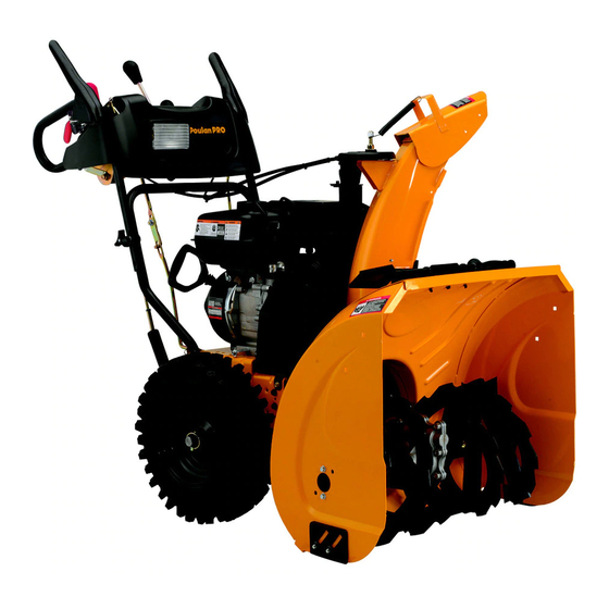
OWNER'S MANUAL
MODEL NUMBER:
PR624ES
SNOW THROWER
Always Wear Eye Protection During Operation
Gasoline containing up to 10% ethanol (E10) is acceptable for use in this machine.
The use of any gasoline exceeding 10% ethanol (E10) will void the product warranty.
581 45 58-27
DO NOT THROW AWAY
WARNING:
Read the Owner's Manual and
fol low all Warnings and Safety
In struc tions. Fail ure to do so
can result in serious injury.
Advertisement
Table of Contents

Related Manuals for Poulan Pro PR624ES


Summary of Contents for Poulan Pro PR624ES
-
Page 1: Snow Thrower
IMPORTANT MANUAL DO NOT THROW AWAY OWNER'S MANUAL MODEL NUMBER: WARNING: PR624ES Read the Owner's Manual and fol low all Warnings and Safety In struc tions. Fail ure to do so can result in serious injury. SNOW THROWER Always Wear Eye Protection During Operation Gasoline containing up to 10% ethanol (E10) is acceptable for use in this machine. -
Page 2: Safety Rules
IMPORTANT Safe Operation Practices for Walk-Behind Snow Throwers This snow thrower is capable of amputating hands and feet and throwing objects. Failure to observe the following safety instructions could result in serious injury. WARNING: Snow throwers have ex- Look for this symbol to point out im- posed rotating parts, which can cause por tant safety precautions. -
Page 3: Table Of Contents
Clearing a Clogged Discharge Chute 6. When cleaning, repairing or inspecting the snow thrower, stop the engine and make certain the collector/impel- Hand contact with the rotating impeller inside the discharge ler and all moving parts have stopped. Disconnect chute is the most common cause of injury associated with the spark plug wire and keep the wire away from the snow throwers. - Page 4 PARTS PACKED SEPARATELY IN CARTON (1) POWER CORD (1) MULTI- (198563) WRENCH (180684) (3) RETAINER SPRINGS (169675) (2) LOCKNUTS (2) SHEAR BOLTS 1/4-20 x 1-3/4 1/4-20 (192090) (2) FLAT WASHERS (73800400) (2) CARRIAGE BOLTS 3/8-16 x 2.25 SAFTEY IGNITION KEY(S) (1) LOCKNUT 3/8 (1) WASHER 3/8 (443059)
-
Page 5: Assembly / Pre-Operation
ASSEMBLY / PRE-OPERATION Read these instructions and this manual in its entirety before you attempt to assemble or operate your new snow thrower. Reading the entire manual will familiarize you with the unit, which will assist you in assembly, operation and maintenance of the product. Your new snow thrower has been as sem bled at the factory with the ex cep tion of those parts left unassembled for shipping purposes. - Page 6 ASSEMBLY / PRE-OPERATION INSTALL TRACTION DRIVE CONTROL ROD INSTALL AUGER CONTROL ROD (See Figs. 5 and 6) (See Figs. 3 and 4) 1. Retrieve vinyl sleeve and spring from bag of parts and retrieve the auger control rod from carton chute tray. The traction drive control rod is installed on the snow thrower.
-
Page 7: Assembly / Pre-Operation
ASSEMBLY / PRE-OPERATION INSTALL DISCHARGE CHUTE / CHUTE ROTATER INSTALL CHUTE DEFLECTOR REMOTE CONTROL HEAD (See Fig. 7) (See Figs. 8 and 9) 1. Install remote cable bracket to discharge chute with NOTE: The multi-wrench provided in your parts bag may 5/16-18 carriage bolt and 5/16-18 locknut as shown. -
Page 8: Operation
OPERATION KNOW YOUR SNOW THROWER READ THIS OWNER'S MANUAL AND ALL SAFETY RULES BEFORE OPERATING YOUR SNOW THROWER. Compare the illustrations with your snow thrower to familiarize yourself with the location of various controls and adjustments. Save this manual for future reference. These symbols may appear on your snow thrower or in literature supplied with the product. - Page 9 OPERATION MUF FLER ELECTRIC AUGER DISCHARGE CHUTE CONTROL LEVER START CONTROL BUTTON LEVER DEFLECTOR TRACTION DRIVE SPEED GAS O LINE REMOTE DRIVE CON TROL LEVER FILLER CAP CONTROL CONTROL POWER LEVER LEVER CORD PLUG CHUTE CHOKE DE FLEC TOR CON- TROL SAFETY IGNITION...
- Page 10 OPERATION TO CONTROL SNOW DISCHARGE (See Fig. 13) The operation of any snow thrower can result in foreign objects thrown into the eyes, which WARNING: Snow throwers have ex- can result in severe eye damage. Always wear posed rotating parts, which can cause safety glasses or eye shields while operating severe injury from contact, or from ma- your snow thrower or performing any ad just-...
-
Page 11: Using The Clean-Out Tool
OPERATION TO MOVE FORWARD AND BACKWARD (See Fig. 16) USING THE CLEAN-OUT TOOL (See Fig. 15) SELF-PROPELLING, forward and reverse movement of In certain snow conditions, the discharge chute may be- the snow thrower, is controlled by the traction drive control come clogged with ice and snow. -
Page 12: Before Starting The Engine
OPERATION BEFORE STARTING THE ENGINE TO ADJUST SKID PLATES (See Fig. 18) NOTE: The wrench provided in your parts bag may be CHECK ENGINE OIL LEVEL (See Fig. 19) used to adjust the skid plates. The engine on your snow thrower has been shipped from the factory already filled with oil. -
Page 13: Snow Throwing Tips
OPERATION TO START ENGINE 6. When the engine starts, release the recoil starter han dle and slowly move the choke control to the “OFF” position. • Be sure fuel shut-off valve is in the “OPEN” position. Allow the engine to warm up for a few minutes. Engine will Your snow thrower engine is equipped with both a 120 Volt not develop full power until it has reached normal operat- A.C. -
Page 14: Maintenance Schedule
MAINTENANCE GENERAL REC OM MEN DA TIONS LUBRICATION CHART The warranty on this snow thrower does not cover items SAE 5W-30 Motor Oil that have been sub ject ed to operator abuse or negligence. To receive full value from the warranty, operator must See “ENGINE”... -
Page 15: Cleaning
MAINTENANCE SNOW THROWER Check the crankcase oil level before starting the engine and after each five (5) hours of continuous use. Tighten oil Always observe safety rules when performing main te nance. fill cap / dipstick securely each time you check the oil level. TIRES TO CHANGE ENGINE OIL •... -
Page 16: Service And Adjustments
SERVICE AND ADJUSTMENTS To replace the capscrew/shear bolts: WARNING: To avoid serious injury, before 1. Disengage all controls and move throttle control to performing any service or ad just ments: STOP position. Wait for all moving parts to stop. 1. Ensure the on/off switch is in the OFF 2. -
Page 17: To Replace Belts
SERVICE AND ADJUSTMENTS TO REPLACE BELTS (See Fig. 22) HINT: Insert a 3/8" drive ratchet (in the “ON” position) into the square hole in idler arm and rotate ratchet clockwise The auger and traction drive belts are not adjustable. If the to relieve tension. - Page 18 SERVICE AND ADJUSTMENTS TO REMOVE WHEELS (See Fig. 23) TO ADJUST CABLE TENSION (See Fig. 24) • Remove the wheel pin and retainer pin and remove Adjust cable tension by turning the adjuster turn buckle, wheel from axle. located on the right hand cable. Grasp the long section tightly and turn the short section to lengthen the adjuster.
-
Page 19: Storage
STORAGE Immediately prepare your snow thrower for storage at • Empty the fuel tank by starting the engine and letting it run until the fuel lines and car bu re tor are empty. the end of the season or if the unit will not be used for 30 days or more. -
Page 20: Troubleshooting
TROUBLESHOOTING See appropriate section in manual unless directed to an authorized service center/department. PROBLEM CAUSE CORRECTION Does not start 1. Fuel shut-off valve (if so 1. Turn fuel shut-off valve to OPEN position. equipped) in OFF position. 2. Safety ignition key 2. -
Page 21: Repair Parts
SNOW THROWER - MODEL PR624ES (96198004604) REPAIR PARTS AUGER HOUSING / IMPELLER ASSEMBLY PART DESCRIPTION 532 43 88-28 AUGER HOUSING 532 40 78-25 SCRAPER BAR 872 27 05-05 CARRIAGE BOLT 5/16−18 X .625 532 15 53-77 NUT 5/16−18 3 (5x) 4 (5x) 01.07.001-A... - Page 22 SNOW THROWER - MODEL PR624ES (96198004604) REPAIR PARTS AUGER HOUSING / IMPELLER ASSEMBLY 2 (EXPLODED) 01.07.026-F NOTE: All component dimensions given in U.S. inches. 1 inch = 25.4 mm IMPORTANT: Use only Original Equipment Manufacturer (O.E.M.) replacement parts. Failure to do so could be hazardous, damage your snow thrower and void your warranty.
- Page 23 SNOW THROWER - MODEL PR624ES (96198004604) REPAIR PARTS AUGER HOUSING / IMPELLER ASSEMBLY PART DESCRIPTION 532 18 41-05 IMPELLER 532 42 71-48 GEARBOX ASSEMBLY 532 18 89-09 BEARING 532 42 71-46 IMPELLER PULLEY 532 44 24-38 DISCHARGE BASE 532 18 40-95...
- Page 24 SNOW THROWER - MODEL PR624ES (96198004604) REPAIR PARTS AUGER HOUSING / IMPELLER ASSEMBLY PART DESCRIPTION 532 43 59-51 PLATE SKID PLASTIC HDPE 532 42 65-89 NUT 5/16-18 LARGE HEX FLANGE BLK 872 11 05-10 CARRIAGE BOLT 5/16-18 X 1.25 01.11.003-B...
- Page 25 SNOW THROWER - MODEL PR624ES (96198004604) REPAIR PARTS CONTROL PANEL / DISCHARGE CHUTE PART DESCRIPTION 532 44 42-39 CHUTE WELDMENT 532 43 88-32 DEFLECTOR WELDMENT 532 42 06-73 DEFLECTOR CONTROL ASSEMBLY 532 42 03-25 DEFLECTOR SEAL 532 41 42-80 KNOB BLACK...
- Page 26 SNOW THROWER - MODEL PR624ES (96198004604) REPAIR PARTS CONTROL PANEL / DISCHARGE CHUTE PART DESCRIPTION 532 42 82-72 LEVER/CABLE ROTATOR ASSEMBLY 817 50 10-10 SCREW 10-24 X .625 01.09.010-B 532 42 06-78 ROTATOR HEAD 532 40 59-32 ROTATOR PIVOT BRACKET...
- Page 27 SNOW THROWER - MODEL PR624ES (96198004604) REPAIR PARTS HANDLES PART DESCRIPTION 532 42 11-20 LOOP HANDLE LH 532 42 11-21 LOOP HANDLE RH 874 78 05-24 SCREW 5/16−18 X 1.50 532 75 11-53 NUT 5/16−18 532 05 56-11 WASHER FLAT 01.08.004-C...
- Page 28 SNOW THROWER - MODEL PR624ES (96198004604) REPAIR PARTS HANDLES 01.08.002-J PART DESCRIPTION 532 41 55-39 CONTROL PANEL 580 68 78-02 CONTROL LEVER LH 580 68 77-02 CONTROL LEVER RH 532 41 55-46 TRACTION ROD ARM 532 42 90-98 IMPELLER ROD ARM...
- Page 29 SNOW THROWER - MODEL PR624ES (96198004604) REPAIR PARTS HANDLES PART DESCRIPTION 580 79 77-01 IMPELLER ROD ASSEMBLY 580 79 79-01 TRACTION ROD ASSEMBLY 532 18 04-45 SHIFTER ROD TOP 532 18 77-16 SHIFTER ROD BOTTOM 532 18 04-47 SPRING SLEEVE...
- Page 30 SNOW THROWER - MODEL PR624ES (96198004604) REPAIR PARTS HANDLES PART DESCRIPTION 532 41 62-88 INTERLOCK SPRING 532 44 52-91 INTERLOCK CAM 532 44 32-15 TORSION SPRING 532 16 96-75 RETAINER 817 06 04-10 SCREW 1/4−20 X .625 532 42 18-14 INTERLOCK STOP 01.08.007-D...
- Page 31 SNOW THROWER - MODEL PR624ES (96198004604) REPAIR PARTS DRIVE 01.03.002-B PART DESCRIPTION 532 40 49-23 AXLE ASSEMBLY (ASSY OF 1A,1B) 532 40 43-07 AXLE SHAFT 532 18 42-06 ROLL PIN 3/16 X 1.50 532 40 26-91 SPROCKET 532 44 49-49...
- Page 32 SNOW THROWER - MODEL PR624ES (96198004604) REPAIR PARTS DRIVE ITEM 42 EXPLODED 01.02.013-C...
- Page 33 SNOW THROWER - MODEL PR624ES (96198004604) REPAIR PARTS DRIVE PART PART DESCRIPTION DESCRIPTION 532 19 88-75 SPEED SELECTOR ASSEMBLY 532 17 53-44 BEARING 817 50 10-10 SCREW 10-24 X .625 532 17 86-13 WHEEL HUB 532 43 88-37 END PLATE 874 76 05-14 SCREW 5/16-18-.875...
-
Page 34: Chassis/Engine/Pulleys
SNOW THROWER - MODEL PR624ES (96198004604) REPAIR PARTS CHASSIS / ENGINE / PULLEYS PART DESCRIPTION 580 42 60-01 COMPLETE LCT ENGINE PW2HK1865017-8E 01.00.034-A 532 43 88-40 FRAME 532 15 04-06 BOLT 3/8-16 532 42 88-67 SCREW 5/16-18 X .750 PART... - Page 35 SNOW THROWER - MODEL PR624ES (96198004604) REPAIR PARTS CHASSIS / ENGINE / PULLEYS 01.21.003-D PART DESCRIPTION 40 80-07 IMPELLER BELT 41 97-44 TRACTION BELT 42 92-71 IDLER ARM BRACKET 18 05-23 IDLER PULLEY 42 65-89 NUT 5/16-18 874 78 05-24 SCREW 5/16-18 X 1 .50...
- Page 36 SNOW THROWER - MODEL PR624ES (96198004604) REPAIR PARTS WHEELS 13 13 PART DESCRIPTION 532 40 51-61 COVER 532 18 44-71 SHOULDER SCREW 812 00 00-45 RETAINER RING 01.15.001-D 532 19 21-26 WHEEL DRIVER 532 18 24-66 RETAINER RING 532 18 76-22...
- Page 37 SNOW THROWER - MODEL PR624ES (96198004604) REPAIR PARTS WHEELS PART DESCRIPTION 532 43 94-08 WHEEL ASSEMBLY LH 532 43 94-09 WHEEL ASSEMBLY RH 01.06.015-A PART DESCRIPTION 532 43 84-46 CABLE BRACKET LH 532 43 84-47 CABLE BRACKET RH 817 49 04-08 SCREW 1/4-20 X .500...
- Page 38 SNOW THROWER - MODEL PR624ES (96198004604) REPAIR PARTS BAG OF PARTS PART DESCRIPTION 532 19 85-63 POWER CORD 532 16 96-75 RETAINER PIN 532 42 91-12 WRENCH 532 18 45-05 REMOTE SPRING 532 17 98-29 SHOULDER BOLT 1/4-20 532 19 17-30...
-
Page 39: Repair Parts
SNOW THROWER - MODEL PR624ES (96198004604) REPAIR PARTS DECALS PART DESCRIPTION 532 18 10-37 DECAL, DANGER 532 18 10-35 DECAL, DANGER, DEFLECTOR 532 18 10-42 DECAL, DANGER 532 18 10-33 DECAL, INSTRUCTION 581 43 01-01 DECAL, SPEED CONTROL/TRIGGER 581 43 01-02... -
Page 40: Warranty
LIMITED WARRANTY The Manufacturer warrants to the original consumer purchaser that this product as manufactured is free from defects in mate- rials and work man ship. For a period of two (2) years from date of purchase by the original consumer purchaser, we will repair or replace, at our option, without charge for parts or labor incurred in replacing parts, any part which we find to be defective due to materials or workmanship.