Nokia N8-00 Service Manual
Rm-596
Hide thumbs
Also See for N8-00:
- User manual (145 pages) ,
- User giude (131 pages) ,
- Service manual (33 pages)
Table of Contents
Advertisement
Quick Links
1
SERVICE MANUAL
Level 1&2
RM-596
Transceiver characteristics
Band
WCDMA HSPA 850/900/1700/1900/2100
EGSM 850/900/1800/1900
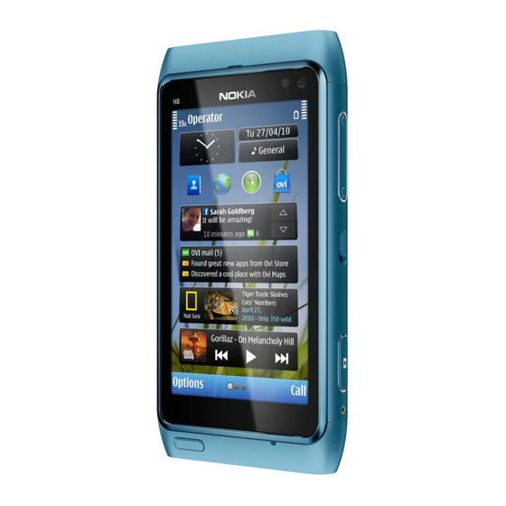
Display
3.5" AMOLED, up to 16.7 million colors, 16:9
widescreen aspect ratio, 640x360 pixel resolution
Camera
12 Mpix Carl Zeiss autofocus camera with CMOS
sensor, Xenon flash, 1280x720 25 fps HD video
recording
Operating System
Symbian^3
Connections:
HDMI connector with Dolby Digital 5.1 audio, analog
TV out with stereo audio via 3.5 mm AV connector,
Micro USB 2.0 with OTG support, Bluetooth 3.0, WLAN
802.11 b/g/n
Transceiver with BL-4D battery pack
Talk time
GSM:
Up to 12 hours
WCDMA:
Up to 5.8 hours
Note:
Talk times are dependent on network parameters
and phone settings
Confidential | Copyright © 2010 Nokia | All rights reserved
Nokia N8-00
Service Manual Level 1&2
Standby
GSM:
Up to 390 hours
WCDMA:
Up to 400 hours
RM-596
Version 3.0
Advertisement
Table of Contents

Related Manuals for Nokia N8-00


Summary of Contents for Nokia N8-00
- Page 1 Up to 12 hours Up to 390 hours WCDMA: WCDMA: Up to 5.8 hours Up to 400 hours Note: Talk times are dependent on network parameters and phone settings Confidential | Copyright © 2010 Nokia | All rights reserved Version 3.0...
-
Page 2: Table Of Contents
BATTERY INFORMATION ..............................8 EXPLODED VIEW ................................. 9 SERVICE DEVICES ................................11 SOFTWARE UPDATE ................................12 DISASSEMBLY INSTRUCTIONS ............................13 10. ASSEMBLY INSTRUCTIONS ............................... 23 11. SOLDER COMPONENTS ..............................32 Confidential | Copyright © 2010 Nokia | All rights reserved Version 3.0... - Page 3 Torx sizes corrected for disassembly and exploded view The purpose of this document is to help NOKIA service levels 1 and 2 workshop technicians to carry out service to NOKIA products. This Service Manual is to be used only by authorized NOKIA service suppliers, and the content of it is confidential.
-
Page 4: Copyright
Nokia operates a policy of continuous development. Nokia reserves the right to make changes and improvements to any of the products described in this document without prior notice. Under no circumstances shall Nokia be responsible for any loss of data or income or any special, incidental, consequential or indirect damages howsoever caused. -
Page 5: Warnings And Cautions
3. Use only approved components as specified in the parts list. 4. Ensure all components, modules screws and insulators are correctly re–fitted after servicing and alignment. 5. Ensure all cables and wires are repositioned correctly Confidential | Copyright © 2010 Nokia | All rights reserved Version 3.0... -
Page 6: Esd Protection
RM-596 Service Manual Level 1&2 3. ESD PROTECTION Nokia requires that service points have sufficient ESD protection (against static electricity) when servicing the phone. Any product of which the covers are removed must be handled with ESD protection. The SIM card can be replaced without ESD protection if the product is otherwise ready for use. -
Page 7: Care And Maintenance
All of the above suggestions apply equally to the product, battery, charger or any accessory. Confidential | Copyright © 2010 Nokia | All rights reserved Version 3.0... -
Page 8: Battery Information
Batteries’ performance is particularly limited in temperatures well below freezing. Do not dispose batteries in a fire! Dispose of batteries according to local regulations (e.g. recycling). Do not dispose as household waste. Confidential | Copyright © 2010 Nokia | All rights reserved Version 3.0... -
Page 9: Exploded View
Nokia N8-00 RM-596 Service Manual Level 1&2 6. EXPLODED VIEW Confidential | Copyright © 2010 Nokia | All rights reserved Version 3.0... - Page 10 Nokia N8-00 RM-596 Service Manual Level 1&2 Confidential | Copyright © 2010 Nokia | All rights reserved Version 3.0...
-
Page 11: Service Devices
Service Bulletin (SB-011) on Nokia Online. Supplier or manufacturer contacts for tool re-order can be found in “Recommended service BL-4D Battery SS-182 Camera Removal tool equipment” document on Nokia Online. Confidential | Copyright © 2010 Nokia | All rights reserved Version 3.0... -
Page 12: Software Update
To use the FLS-5 Flash Dongle, follow the user guide inside the sales package. Please check always for the latest version of flash software, which is available on Nokia Online. Confidential | Copyright © 2010 Nokia | All rights reserved... -
Page 13: Disassembly Instructions
5) Unscrew also the second Torx+ size 4 screw on the 6) Pull out the BOTTOM COVER to the direction shown other side of the phone 7 full turns. Do not remove and remove it. the screw completely! Confidential | Copyright © 2010 Nokia | All rights reserved Version 3.0... - Page 14 11) Unscrew the Torx+ size 5 screw. Do not use it 12) Remove the TOP COVER by pushing it from the again. Discard it. back side to the direction shown. Confidential | Copyright © 2010 Nokia | All rights reserved Version 3.0...
- Page 15 Be CONNECTOR. Be careful not to damage the connector careful not to damage the connectors while lifting or components nearby! up the WINDOW ASSY! Confidential | Copyright © 2010 Nokia | All rights reserved Version 3.0...
- Page 16 DISPLAY. Be careful not to damage the DISPLAY while releasing it! 23) Protect the other side of the WINDOW ASSY with 24) Protect the DISPLAY with protective film. protective film. Confidential | Copyright © 2010 Nokia | All rights reserved Version 3.0...
- Page 17 29) Use tweezers to remove the two WINDOW FRAME 30) Remove the EARPIECE GASKET with the tweezers. FIXING SPRINGS. Do not use them again. Discard Do not use it again. Discard it. them. Confidential | Copyright © 2010 Nokia | All rights reserved Version 3.0...
- Page 18 35) Remove the FRONT CAMERA BOOT with the 36) Lift up the AV JACK carefully as shown before tweezers. Do not use it again. Discard it. releasing the ENGINE BOARD. Confidential | Copyright © 2010 Nokia | All rights reserved Version 3.0...
- Page 19 41) Use the SS-93 to release the PWB SPACER ASSY. Be 42) Remove the PWB SPACER ASSY. Do not use it careful not to damage the components nearby! again. Confidential | Copyright © 2010 Nokia | All rights reserved Version 3.0...
- Page 20 46) Pull out and remove the MICRO SD CARD HATCH. not use it again. Discard it. 47) Remove also the SIM CARD HATCH. 48) Carefully lever out the FLASH MODULE with the SS- Confidential | Copyright © 2010 Nokia | All rights reserved Version 3.0...
- Page 21 52) Remove the screw and the FIXING NUT with the FIXING NUT. tweezers. 53) To release the second FIXING NUT, unscrew the 54) Remove the screw with the tweezers. Torx+ size 4 screw. Confidential | Copyright © 2010 Nokia | All rights reserved Version 3.0...
- Page 22 Nokia N8-00 RM-596 Service Manual Level 1&2 55) Remove the FIXING NUT. 56) The Nokia N8-00 disassembly is now complete. -END OF DISASSEMBLY- Confidential | Copyright © 2010 Nokia | All rights reserved Version 3.0...
-
Page 23: Assembly Instructions
5) Press the PWB SPACER ASSY along the edges with 6) Place the SUB PWB on top of the PWB SPACER ASSY. the SS-93 to activate the adhesive. Be careful not to damage the flex! Confidential | Copyright © 2010 Nokia | All rights reserved Version 3.0... - Page 24 12) Place the FLASH MODULE with the tweezers. dental tool to lever the SIDE SWITCH under the two shown clips. Be careful not to injure yourself with the sharp end of the dental tool! Confidential | Copyright © 2010 Nokia | All rights reserved Version 3.0...
- Page 25 18) Place the IHF SPEAKER. Make sure that the IHF down carefully with the SS-93 to activate the SPEAKER springs point towards the FLASH MODULE. adhesive. Press the speaker with the SS-93 to activate the adhesive. Confidential | Copyright © 2010 Nokia | All rights reserved Version 3.0...
- Page 26 23) Remove the EARPIECE ADHESIVE protective film. 24) Place the EARPIECE ADHESIVE and activate the adhesive by carefully pressing down on it with the SS-93. Remove the blue EARPIECE ADHESIVE protective film. Confidential | Copyright © 2010 Nokia | All rights reserved Version 3.0...
- Page 27 30) Use the SS-93 to spread the sides of the BODY SPRINGS, press down on the shown places to get the ASSY and push down the ENGINE CHASSIS ASSY to lock springs correctly in their place. the springs. Confidential | Copyright © 2010 Nokia | All rights reserved Version 3.0...
- Page 28 SS-93. Be careful with the SS-93. Be careful not to damage the not to damage the connector or components nearby! connector or components nearby! Confidential | Copyright © 2010 Nokia | All rights reserved Version 3.0...
- Page 29 42) Tighten the TORX + size 5 screw to the torque of the TOP COVER is in its place by firmly pressing on 11 Ncm. both corners of the TOP COVER. Confidential | Copyright © 2010 Nokia | All rights reserved Version 3.0...
- Page 30 Note that the BATTERY PULL-OUT TAPE is left under the BATTERY LID. 47) Remove the protective film of the BOTTOM DECO 48) And attach it to the BOTTOM COVER. ASSY. Confidential | Copyright © 2010 Nokia | All rights reserved Version 3.0...
- Page 31 51) Hold the BOTTOM COVER in its place and tighten 52) Nokia N8-00 assembly is now complete. the TORX + size 4 screws to the torque of 21 Ncm on both sides. -END OF ASSEMBLY- Confidential | Copyright © 2010 Nokia | All rights reserved Version 3.0...
-
Page 32: Solder Components
Service Manual Level 1&2 11. SOLDER COMPONENTS S2401 S2402 S2400 F3350 X7402 V2422 S2403 V2420 G2200 F3300 V2411 V2410 X2500 BOTTOM X3300 X1650 X6700 X6702 X7403 X7404 Ver. 1.0 Confidential | Copyright © 2010 Nokia | All rights reserved Version 3.0...