
Related Manuals for Husqvarna 225 HBV


Summary of Contents for Husqvarna 225 HBV
- Page 1 225 HBV Operator´s manual Read the operator’s manual carefully and make sure that you understand the contents before using the blower. EPA Version 101 90 68-95...
- Page 2 Svenska –...
-
Page 3: Table Of Contents
Safety instructions ... 4 Description... 6 Fuel handling ... 11 Starting and stopping ... 13 Using the blower ... 14 Maintenance... 18 Technical data... 25 Maintenance, replacement, or repair of the emission control devices and systems may be performed by any nonroad engine repair establishment or individual. -
Page 4: Introduction
Husqvarna AB has a policy of continuous product development and therefore reserves the right to modify the design and appearance of products without prior notice. This operator’s manual describes in detail how to use and service the blower and how to carry out regular maintenance. -
Page 5: Key To Symbols
Read the operator’s man-ual carefully and make sure that you understand the contents before using the blower. WARNING! Make sure that the inspection cover is locked in the closed position or that the vacuum tube is mounted on the blower. -
Page 6: Safety Instructions
SAFETY INSTRUCTIONS Personal safety equipment Persons who use the blower shall wear the following safety equipment: 1. Approved ear protection. 2. Approved eye protection. 3. Face mask when operating the blower in dusty environments. 4. Boots or work shoes with a non-slip sole. - Page 7 3. Never point the blower nozzle toward people or animals. 4. Stop the engine before fitting or dismantling accessories or other components. 5. Never operate the blower if any of the guards is missing. 6. Never operate the blower in poorly ventilated spaces where exhause fumes might otherwise be inhaled.
-
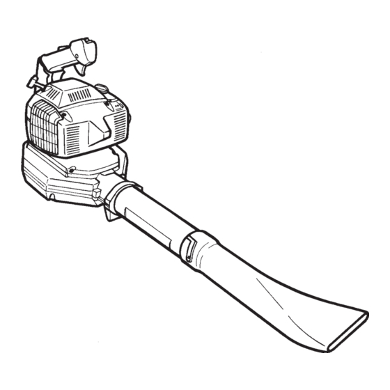
Page 8: Description
9. Air filter 10. Choke – English DESCRIPTION 11. Inspection cover 12. Cutters 13. Fan impeller 14. Nozzle 15. Blower tube 16. Muffler 17. Start handle 18. Starter device 19. Carburetor adjustment screws 20. Operator’s manual 21. High velocity nozzle. 7 13... - Page 9 Accessories 21. Vacuum device with collection components consisting of items 22 - 25 below. 22. Vacuum bag tube. 23. Collection bag. 24. Vacuum tube in two sections. 25. Auxiliary handle. DESCRIPTION English –...
- Page 10 Safety equipment The following equipment on the blower is designed for protecting personnel and materials. These com- ponents should receive special attention whenever you operate, inspect and service the blower. Stop switch (3) The stop switch is used to stop the engine.
- Page 11 The nozzle and the blower tube have a bayonet mount for connection to the blower. Air is channeled through the blower tube to the nozzle, where the air discharge velocity increases and the air stream dis- charge pattern is formed to provide best perform- ance.
- Page 12 The air filter consists of foam-rubber filter medium, integrated in a plastic casing. The air filter should be cleaned at specific intervals. Otherwise, the power blower will consume too much fuel, the performance will be reduced and an oily deposit may form on the spark plug electrodes.
-
Page 13: Fuel Handling
Husqvarna two-stroke engines. Mixing ratio: 1:50 (2%). • If HUSQVARNA two-stroke oil is not available, you may use another two-stroke oil of good quality that is intended for air-cooled engines. Contact your dealer when selecting an oil. - Page 14 Mixture • Always mix gasoline and oil in a clean container intended for fuel. • Always start by filling half the quantity of gasoline required. Then add the entire oil quantity. Mix (shake) the fuel mixture. Fill the remaining quantity of gasoline. •...
-
Page 15: Starting And Stopping
Doing so will damage the starter 3. Press the blower against the ground and pull the starter handle slowly until resistance is felt (when the starter pawls engage). Then pull it with quick, vigorous movements. -
Page 16: Using The Blower
The blower tube and nozzle have a bayonet mount. Fit them in the following manner: 1. Press the blower tube (15) against the blower air outlet and turn it 90 degrees until a snap is heard. - Page 17 WARNING! Never point the blower nozzle at people or animals. The high-velocity air stream can contain particles that may cause serious injury, especially if the blower has previously been used for vacuuming. Be careful, particurlarly if left hand operation is applied. Avoid any direct body contact with the exhaust outlet area.
- Page 18 Close the zipper on the bag. 2. Press the collection bag tube on the blower, turn it 1/4 of a turn until a snap is heard. The section...
- Page 19 Avoid any direct body contact with the exhaust outlet area. Start the blower as described on page 13. Work ac- cording to the following instructions: 1. Do not vacuum large solid objects that can damage the fan, such as wood, cans (tins) or lengths of string or ribbon.
-
Page 20: Maintenance
California Air Resources Board. Low speed jet, L 1. Check that the blower tube (15) and the nozzle (14) are mounted on the blower. 2. Turn the H and L adjustment screws fully counter- clockwise so that they rest against the stop. -
Page 21: Cooling System
4. Cylinder cowling (guides cooling air flow against cylinder surfaces). Clean the cooling system by brushing once a week, or more often, if necessary. A dirty or blocked cooling system will cause the blower to overheat and this will damage the cylinder and piston. MAINTENANCE English –... -
Page 22: Air Filter
A dirty air filter. These factors cause deposits on the spark plug electrodes, which may result in malfunction and difficulty starting the blower. If the engine is low on power, difficult to start or runs poorly at idling speed, always check the spark plug first. - Page 23 To change a broken or worn cord 1. Unscrew the screws (A) to remove the starter device from the blower. 2. Pull out the cord approx. 30 cm (12”) and lift it up into the notch in the periphery of the pulley.
- Page 24 To change the recoil spring 1. Dismantle the pulley according to items 1 to 5 in the instructions on the preceding page. WARNING! The recoil spring may pop out and cause injury. Wear protective goggles or a visor. 2. Carefully lift out the recoil spring. 3.
-
Page 25: Maintenance Schedule
If more detailed instructions are required, get in touch with your local servicing dealer. Daily maintenance 1. Clean the exterior surfaces of the blower. 2. Check that the throttle lock and the throttle trig- ger function in a safe manner. Replace damaged parts. -
Page 26: Monthly Maintenance
Monthly maintenance 1. Flush the fuel tank with clean gasoline, which afterward should be disposed of in an environ- mentally correct manner. 2. Clean the outside of the carburetor and the space around it. Replace damaged parts. 3. Clean the fan blades on the flywheel and the space around it. -
Page 27: Technical Data
Electrode gap, mm: Fuel and lubrication system Manufacturer/type of carburetor: Fuel tank volume, liters: Weight Weight, without fuel but with blower tube and standard nozzle fitted, kg: Noise levels Equivalent noise pressure level at operator’s ear. Weighted value for 50%... -
Page 28: Emission Control Warranty Statement
REPAIR OR REPLACEMENT OF PARTS Repair or replacement of any warranted part will be performed at no charge to the owner at an approved Husqvarna Forest & Garden servicing dealer. If you have any questions regarding your warranty rights and responsibilities, you should contact your nearest authorized servicing dealer or call Husqvarna Forest &... - Page 29 Svenska –...
- Page 30 Svenska –...
- Page 31 Svenska –...
- Page 32 2000W01...