Table of Contents
Advertisement
Advertisement
Table of Contents

Related Manuals for Invacare Pegasus


Summary of Contents for Invacare Pegasus
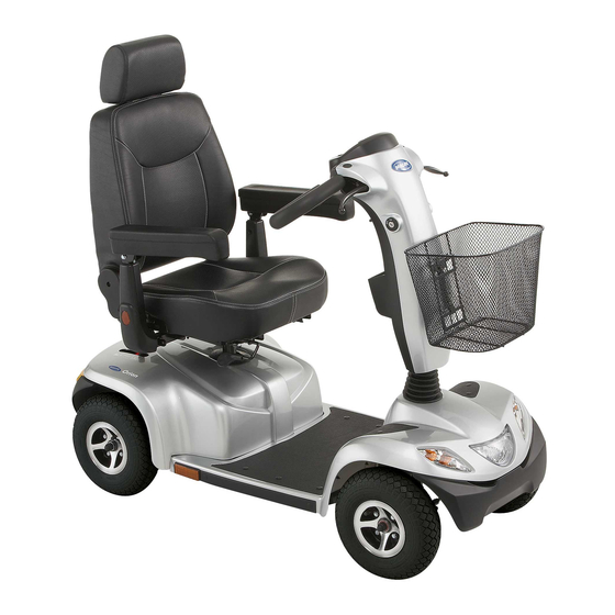
- Page 1 Yes, You Can.® Invacare® Pegasus Scooter Operating manual...
- Page 2 How can you get in touch with Invacare®? If you have any questions or need support, please contact your authorised Invacare® Dealer, who has the necessary know-how and equipment plus the special knowledge concerning your Invacare® product, and can offer you all-round satisfactory service. Should you wish to contact Invacare® directly, you can reach us in Europe at the following addresses and phone numbers.
-
Page 3: Table Of Contents
Table of Contents Chapter Page Introduction Guarantee........................7 Important symbols in this manual ................... 8 Important symbols found on the v ehicle ............... 10 Type classification and permissible use................ 11 Life expectancy ......................11 Safety notes General safety notes...................... 12 Safety information w ith regard to care and maintenance.......... - Page 4 Operating Console Arrangement................... 26 6.1.1 Status Display ..................... 27 6.1.2 Battery Charge Display ..................27 Driv ing the Scooter......................28 Activ ating and Deactivating Acoustic Signals............... 29 Activ ating and Deactivating Speed Reduction During Bend Trav el....... 33 Diagnosis and fault repair .................... 34 6.5.1 Error diagnosis ....................
- Page 5 Care and maintenance 10 Repair Instructions 10.1 Repairing a flat tire ....................... 60 10.1.1 Mending punctures (pneumatic tires of type 4.10 / 3.50 - 5)........61 10.1.1.1 Repairing punctured tires................62 11 Disposal 12 Technical specifications 13 Inspections Performed...
-
Page 6: Introduction
The decision whether the model is suitable for the user may only be taken by medical specialists with appropriate aptitude. Invacare® or their statutory representatives can accept no liability in cases in which the mobility product has not been adapted to suit the user's handicaps. -
Page 7: Guarantee
This manual contains copyrighted information. It may not be reproduced or copied in whole or in part without the prior written consent of Invacare® or its authorised representative. It may also contain information that pertains to models sold only in certain countries. In this case the information will be clearly marked as pertaining to a particular country-specific version. -
Page 8: Important Symbols In This Manual
1.2 Important symbols in this manual General risks This symbol warns you of general hazards! Always follow the instructions to avoid injury to the user or damage to the product. EXPLOSION HAZARD! This symbol warns you of an explosion hazard, w hich can be caused by excessive tire pressure in a pneumatic tire. - Page 9 Wear eye protection This symbol refers to the requirement for w earing eye protection, for example w hen w orking w ith batteries. You must wear safety goggles when this symbol is displayed. Wear protective gloves This symbol indicates the requirement to wear protective gloves, for example w hen w orking w ith batteries.
-
Page 10: Important Symbols Found On The Vehicle
1.3 Important symbols found on the vehicle This product has been supplied from an env ironmentally aware manufacturer. This product may contain substances that could be harmful to the environment if disposed of in places (landfills) that are not appropriate according to legislation. ... -
Page 11: Type Classification And Permissible Use
1.4 Type classification and permissible use This vehicle was designed for persons whose ability to walk is impaired, but who are still in terms of their eyesight and physically and mentally able to operate an electric vehicle. It has been classified according to EN 12184 as a class B mobility product (for indoor and outdoor areas). -
Page 12: Safety Notes
2 Safety notes READ WELL BEFORE OPERATION! 2.1 General safety notes Danger of inj ury if this scooter is used in any other w ay than the purpose described in this manual! Adhere strictly to the instructions in this user manual! Danger of inj ury if the scooter is driven w hen your ability to driv e is impaired by medication or alcohol! ... - Page 13 Danger of inj ury if the On/Off Button is pressed w hile the vehicle is in motion, due to it coming to an abrupt, sharp stop! If you have to brake in an emergency, simply pull the handbrake until the scooter comes to a halt! Only switch the vehicle off while in motion as a last resort! Danger of inj ury if the scooter is transported in another vehicle w ith the occupant seated in it!
- Page 14 Invacare® for this purpose! Have all electrical installations done by your authorised Invacare® Dealer! Danger of technical failure and inj ury if unauthorised spare parts and components are used! Only use original Invacare® spare parts, which have been approved for use with this vehicle!
-
Page 15: Safety Information With Regard To Care And Maintenance
2.2 Safety information with regard to care and maintenance Danger of accident and loss of guarantee if maintenance is insufficient! For reasons of safety and in order to avoid accidents which result from unnoticed wear, it is important that this electric mobility product undergoes an inspection once every year under normal operating conditions (see inspection plan contained in service instructions). -
Page 16: Safety Information On Electromagnetic Interference
2.3 Safety information on electromagnetic interference This electric vehicle was successfully tested in accordance with International standards as to its compliance with Electromagnetic Interference (EMI) Regulations. However, electromagnetic fields, such as those generated by radio and television transmitters, and cellular phones, can influence the functions of electric vehicles. -
Page 17: Safety Information On Driving And Freewheel Mode
2.4 Safety information on driving and freewheel mode Danger of inj ury if the vehicle tips ov er! Only ever negotiate gradients up to the maximum tilt-resistant gradient and only with the backrest in an upright position, and the seat lifter in the lowest position (if installed)! ... - Page 18 Danger of inj ury if the vehicle tips ov er! (Continued) Never use the vehicle to transport more than one person! Do not exceed the maximum permissible load! When loading the vehicle, always distribute the weight evenly! Always try to keep the centre of gravity of the vehicle in the middle, and as close to the ground as possible! ...
- Page 19 CAUTION: it may be difficult to turn in front of a lift or building entrance because the scooter turning circle may not necessarily comply w ith building standards! Always be aware of the limitations of your scooter, particularly the turning circle capabilities when entering a building or a lift.
-
Page 20: Key Features
3 Key features Disengaging lever Unlocking lever for sliding seat rails (front right below seat) Unlocking lever for swivelling and removing seat (left under the seat, not visible in picture) Operating console Brake lever (right-hand lever) Lever for adjusting steering column inclination (left-hand lever, not visible in picture). -
Page 21: Driving
4 Driving 4.1 Getting in and out The armrests can be swivelled upwards to assist getting in and out. The seat can also be rotated to assist getting in and out. Lift the detent lever (1) Turn the seat to the side. Information on turning the seat The detent automatically engages again after 45°. -
Page 22: Before Driving For The First Time
4.2 Before driving for the first time... Before you take your first trip, you should familiarise yourself well with the operation of the vehi cle and with all operating elements. Take your time to test all functions and driving modes. NOTE: If installed, make sure to properly adjust and use the postural belt each time you use the wheelchair. -
Page 23: Taking Obstacles
4.3 Taking Obstacles Your Scooter can climb obstacles and kerbs of up to 6 cm in height. CAUTION: Danger of Tipping Ov er! Never approach obstacles at an angle but at 90 degrees as shown below. Put your backrest into an upright position before climbing an obstacle. Driv ing up over an obstacle Correct Approach the kerb or obstacle slowly head-on. -
Page 24: Driving Up And Down Gradients
4.4 Driving up and down gradients For information concerning the maximum safe slope, please see chapter "Technical Specifications" starting on page 65. WARNING: Danger of tipping ov er! Only ever drive downhill at a maximu m of 2/3rds of the top speed! ... -
Page 25: Pushing The Scooter By Hand
5 Pushing the scooter by hand The motors of the scooter are equipped with automatic brakes, preventing the scooter from rolling away out of control when the power supply is switched off. When pushing the scooter, the magnetic brakes must be disengaged. 5.1 Disengaging Motors Danger of the vehicle running aw ay! ... -
Page 26: Operating Console
6 Operating Console 6.1 Operating Console Arrangement Status display Speed controller Switching speed reduction during bend travel on and off Horn Left-hand direction indicator (switches itself off automatically after 30 seconds) Battery charge display Speed reduction Warning blinker Right-hand direction indicator (switches itself off automatically after 30 seconds) 10) Lighting... -
Page 27: Status Display
6.1.1 Status Displa y NOTE: The ON/OFF diode is used as a fault display (status display). Chapter "Error Codes and Diagnostic Codes" on page 26 contains an explanation of the error codes. 6.1.2 Battery Charge Display All diodes illuminate: maximum driving range ... -
Page 28: Driving The Scooter
Pull the right-hand drive lever carefully to travel forwards. Pull the left-hand drive lever carefully to travel in reverse. NOTE: The control system is programmed with standard values in the works. Your Invacare®dealer can carry out programming tailored to fit your requirements. -
Page 29: Activating And Deactivating Acoustic Signals
CAUTION: any changes to the drive program can affect the driving characteristics and the tipping stability of the v ehicle! Changes to the drive program may only be carried out by trained Invacare® specialist dealers! Invacare® supplies all mobility products with a standard drive program ex-works. Invacare®... - Page 30 The electronic system must be switched off in order to activate or deactivate an acoustic signal for particular functions, and a particular keystroke combination needs to be entered when switching on again. After a signal for a particular function has been successfully activated/deactivated, a combination of LEDs on the battery charge display will blink as a confirmation.
- Page 31 The keystroke combinations and LED codes for various options are as follows: Function: Keystroke combination LED(s) Condition Acoustic signal at "Lighting" + "direction deactivated low battery capacity indicator left" D1+D2 activated Acoustic signal "Lighting" + "direction deactivated when direction indicator right" indicators actuated D3+D4 activated...
- Page 32 Activ ating or deactivating an acoustic signal Please proceed as follows to activate or deactivate an acoustic signal for a particular function: 1) Switch off the electronic system. 2) Enter the keystroke combination and hold. 3) Switch on the electronic system 4) Wait two seconds until the appropriate blink code is displayed on the battery charge display, then release the keys.
-
Page 33: Activating And Deactivating Speed Reduction During Bend Travel
6.4 Activating and Deactivating Speed Reduction During Bend Travel Your Scooter is fitted with automatic speed reduction which is activated as standard when the Scooter is switched on. This function lowers the Scooter's speed as soon as you start driving round a bend. -
Page 34: Diagnosis And Fault Repair
6.5 Diagnosis and fault repair The electronic system offers diagnostic information to support the technician during the recognition and rectification of faults on the Scooter. If there is a fault, the status display blinks several times, pauses, then blinks again. The type of fault is displayed by the number of blinks in each group, which are also known as the "blink code". -
Page 35: Error Diagnosis
6.5.1 Error diagnosis If the Scooter shows a failure, please use the following guide to locate the fault. NOTE: Before making any diagnosis, ensure that the Scooter has been switched on at the keyswitch. If the status display is OFF: check w hether the keysw itch is SWITCHED ON. -
Page 36: Error Codes And Diagnostic Codes
6.6 Error Codes and Diagnostic Codes Blink Fault Consequence Comments code for the Scooter Battery must be Continues to The batteries are discharged. Charge the charged drive battery as soon as possible. Battery voltage too Stops driving The batteries are depleted. Charge batteries. - Page 37 There is a defect in the braking coil or in the cabling. Check the magnetic brake and cabling for open or short-circuited circuitry. Contact your Invacare® dealer. No neutral position Stops driving Drive lever is not in neutral when the when switching keyswitch was turned.
- Page 38 Motor voltage error Stops driving The motor or its cabling is defective Check the cabling for open or short- circuited circuitry. Miscellaneous Stops driving Contact your Invacare® dealer. internal fault Push/freewheel Stops driving The Scooter has exceeded the ...
-
Page 39: Adjustment Facilities
7 Adjustment facilities 7.1 Moving the seat position forwards or backwards The disengaging lever for adjusting the seat is located front right below the seat Pull the lever (1) to disengage the seat. Slide the seat forwards or backwards into the required position. -
Page 40: Adjusting The Armrest Width
7.2 Adjusting the armrest width The hand wheels for releasing the armrests are located under the seat (1). Turn the hand wheels to loosen the fixing for the armrest. Adjust the armrests to the required width. Retighten the handwheels ... -
Page 41: Adjusting The Armrest Height
7.3 Adjusting the armrest height Requirements: Phillips screwdriver Use the screwdriver to loosen and remove the armrest fixing screw. Adjust the armrests to the required height. Reposition the screw and tighten again. ... -
Page 42: Adjusting Backrest Angle
7.4 Adjusting backrest angle The lever (1) for adjusting the backrest angle is located on the right of the seat. Pull the lever and adjust the backrest to the required angle by leaning forwards or backwards. -
Page 43: Disengaging The Seat To Rotate It Or Remove It
7.5 Disengaging the seat to rotate it or remove it The seat can be turned to one side to make getting in and out of the scooter easier. The seat is also easier to remove from this position. The lever for disengaging the seat is located under the seat (1) on the left. -
Page 44: Adjusting The Seat Height Manually
7.6 Adjusting the seat height manually Requirements: 2x open-ended spanners 17 mm Remove the seat Remove the battery and motor compartment cover. Remove the seat pillar locking bolt using both open-ended spanners. Adjust the seat height. ... -
Page 45: Postural Belts
7.1 Postural belts A postural belt is an option which can either be fixed to the wheelchair ex-works or can be retrofitted by your specialist dealer. If your wheelchair is fitted with a postural belt, your specialist dealer will have informed you about fitting and usage. The postural belt is used to help the wheelchair user keep an optimum sitting position. -
Page 46: Adjusting The Postural Belt Correctly
If the belt is only fastened with a bolted connection, ensure that the connection has not loosened or undone. You can find more information about maintenance work on belts in the service manual, which is available from Invacare®. -
Page 47: Fixing The Containment Belt To The Scooter
7.1.3 Fixing the containment belt to the scooter Requirements: jaw spanner 12 mm jaw spanner 13 mm The fixing points (1) for attaching the belt are located under the seat (the figure shows only the left hand side). - Page 48 Take hold of the belt mounting and hold it in front of the hole in the fixing. Position the bolt (1), screw the nut on from the other side and tighten with a jaw spanner. Repeat the same procedure on the other side of ...
-
Page 49: Electrical System
8 Electrical system 8.1 Electronics protection system The vehicle's electronics are equipped with an overload-protection system. If the motors are put under considerable strain for a longer period of time (for example, when driving up a steep hill) and especially when the ambient temperature is high, then the electronic system could overheat. -
Page 50: The Main Fuse
NOTE A defective main fuse may be replaced only after checking the entire electric system. An Invacare® specialised dealer must perform the replacement. You can find information on the fuse type in chapter "Technical Specifications" starting on page 65. 8.2 Batteries 8.2.1 What you need to know about batteries... - Page 51 The batteries cannot be overcharged with the specified charger. Please use only charging devices in Class 2. This class of chargers may be left unattended during charging. All charging devices which are supplied by Invacare® comply with these requirements.
-
Page 52: Charging The Batteries
Only ever use the battery charger supplied with your vehicle, or a charger that has been approved by Invacare®. Danger of electric shock and damage to the battery charger if it is allowed to get wet! Protect the battery charger from water. - Page 53 The charging socket is located on the left of the steering column Connecting the battery charger Switch off the Scooter. Push the protective cap on the side of the charging socket to the side. Connect the battery charger to the Scooter. ...
-
Page 54: Removing And Fitting Batteries
8.2.3 Removing and fitting batteries WARNING: Danger of inj ury if the batteries are not handled correctly during assembly and maintenance w ork! New batteries should be installed by authorised technicians! Observe the warnings on the batteries! Take into account the heavy weight of the batteries! ... -
Page 55: Removing The Batteries
8.2.3.1 Remov ing the batteries Requirements: Open spanner, 11 mm. Remove the seat. Remove the battery and motor compartment cover. Open the battery retaining strap (1). Unplug the battery connecting plug (2). Remove the batteries. - Page 56 Loosen the blue cable on the negative battery terminal with the open-ended spanner, and remove the cable. Loosen the red cable battery clamp on the positive battery terminal with the open-ended spanner, and remove the cable. Repeat the procedure for the other battery ...
-
Page 57: How To Handle Damaged Batteries Correctly
Only ever transport damaged batteries in an appropriate acid-resistant receptacle. Wash all objects that have come into contact with acid with lots of water. Disposing of dead or damaged batteries correctly Dead or damaged batteries can be given back to your dealer or directly to Invacare®. -
Page 58: Care And Maintenance
9 Care and maintenance NOTE: Have your vehicle checked once a year by an authorised Invacare® dealer in order to maintain it's driving safety and roadworthiness. Cleaning the vehicle When cleaning the vehicle, pay attention to the following points: Only use a damp cloth and gentle detergent. - Page 59 Clean all parts carefully. Once a year you should have your vehicle inspected and serv iced by your authorised dealer. A complete checklist of necessary maintenance w ork can be found in the Service Manual, w hich can be obtained from Invacare®.
-
Page 60: Repair Instructions
"Technical Specifications" on page 65, or consult the Service Manual, available from Invacare® (in this connection please see the addresse s and phone numbers in section "How can you get in touch w ith Invacare®?" on page 2). In case you require assistance, please contact your Invacare® Dealer. -
Page 61: Mending Punctures (Pneumatic Tires Of Type 4.10 / 3.50 - 5)
Remove the wheel by tapping it gently with the rubber hammer on the rear face to carefully loosen it from the axle. Problems w hen removing w heel? It may be necessary to use a special tool Please ask your Invacare® dealer to help you. -
Page 62: Repairing Punctured Tires
10.1.1.1 Repairing punctured tires Requirements inner tube repair set or a new inner tube talcum powder open-ended spanner, 12 mm Remove valve cap. De-inflate the tire by pressing in the centre valve pin. Loosen the 4 bolts (1) with the socket spanner and ... - Page 63 Did the old inner tube get w et during the repair? If you repaired the old inner tube and reused it, and it became wet during repair, it is much easier to refit it into the wheel if you powder it lightly with talcum powder. ...
-
Page 64: Disposal
Electric components and printed circuit boards are disposed of as electronic scrap. Exhausted or damaged batteries can be returned to your medical equipment supplier or Invacare®. Disposal must be carried out in accordance with the respective national legal provisions. ... -
Page 65: Technical Specifications
12 Technical specifications Permissible operating and storage conditions Temperature range for operation -25° … +50 °C according to ISO 7176-9: Temperature range for storage -40° … +65 °C according to ISO 7176-9: Electrical system Motor 6 km/h: S1: 240 W, Max 500 W peak ... - Page 66 Driv ing characteristics Speed 6 km/h 10 km/h 12 km/h Max. safe slope 3-wheel: 8° 4-wheel: 12° Max. climbable obstacle height 8 cm Turning radius 3-wheel: 112.5 cm 4-wheel: 140 cm Drive range in accordance with ...
- Page 67 Loading Max. load 136 kg Axle loads Max. front axle load 3-wheel: 67 kg 4-wheel: 75 kg Max. rear axle load 3-wheel: 171 kg 4-wheel: 170 kg *** Note: T he drive range of an electric wheelchair is strongly influenced by external factors, such as the charging state of the batteries, surrounding temperature, local topography, road surface characteristics, tire pressure, weight of driver, drive style and use of batteries for lighting, servos etc.
-
Page 68: Inspections Performed
It is confirmed by stamp and signature that all jobs listed in the inspection schedule of the Service and Repair Instructions have been properly performed. The list of the inspection jobs to be performed can be found in the Service Manual which is available through Invacare®. Delivery Inspection... - Page 69 Manufacturer: CHIEN TI ENTERPRISE CO. LTD. No. 13, Lane 227, Fu Ying Road Hsin Chuang, Taipei, Taiwan R.O.C. Distribution: Canada Inv acare Canada L.P. 570 Matheson Blvd East Mississauga Ontario L4Z 4G4 Canada Phone: 1-800-668-5324, Fax: 1-800-950-3176...
-
Page 70: Limited Warranty
(24) months from the date of purchase from Invacare or a dealer. Invacare warrants all batteries for a period of six (6) months from the date of purchase from Invacare or a dealer. - Page 71 WRITTEN CONSENT INCLUDING, BUT NOT LIMITED TO, MODIFICATION THROUGH THE USE OF UNAUTHORIZED PARTS OR ATTACHMENTS; PRODUCTS DAMAGED BY REASON OF REPAIRS MADE TO ANY COMPONENT WITHOUT THE SPECIFIC CONSENT OF INVACARE, OR TO A PRODUCT DAMAGED BY CIRCUMSTANCES BEYOND INVACARE'S CONTROL, AND SUCH EVALUATION WILL BE SOLELY DETERMINED BY INVACARE.