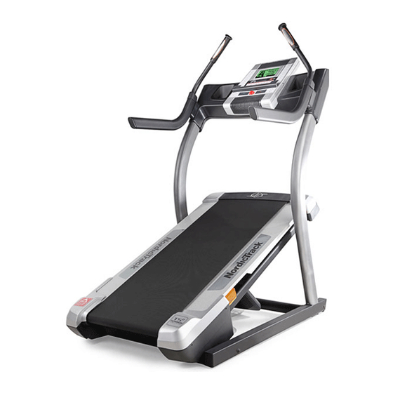
NordicTrack INCLINE TRAINER X5I INTERACTIVE User Manual
Ntl15810.0
Hide thumbs
Also See for INCLINE TRAINER X5I INTERACTIVE:
- Manual (33 pages) ,
- User manual (32 pages) ,
- User manual (34 pages)
Table of Contents
Advertisement
www.nordictrack.com
Model No. NTL15810.0
Serial No.
Write the serial number in the space
above for reference.
Serial Number
QUESTIONS?
If you have questions, or if parts are
damaged or missing, DO NOT
CONTACT THE STORE; please
contact Customer Care.
IMPORTANT: Please register this
product (see the limited warranty
on the back cover of this manual)
before contacting Customer Care.
1-800-TO-BE-FIT
CALL TOLL-FREE:
(1-800-862-3348)
Mon.–Fri. 6 a.m.–6 p.m. MT
Sat. 8 a.m.–4 p.m. MT
ON THE WEB:
www.nordictrackservice.com
CAUTION
Read all precautions and instruc-
tions in this manual before using
this equipment. Save this manual
for future reference.
Decal
USER'S MANUAL
Advertisement
Table of Contents

Related Manuals for NordicTrack INCLINE TRAINER X5I INTERACTIVE


Summary of Contents for NordicTrack INCLINE TRAINER X5I INTERACTIVE
- Page 1 USER'S MANUAL Model No. NTL15810.0 Serial No. Write the serial number in the space above for reference. Serial Number Decal QUESTIONS? If you have questions, or if parts are damaged or missing, DO NOT CONTACT THE STORE; please contact Customer Care.
-
Page 2: Table Of Contents
Apply the decal in the location shown. Note: The decals may not be shown at actual size. NordicTrack is a registered trademark of ICON IP, Inc. -
Page 3: Important Precautions
Do not put the incline page 12. To purchase a surge suppressor, see trainer in a garage or covered patio, or near your local NordicTrack dealer or call the tele- water. phone number on the front cover of this man- ual and order part number 146148, or see your 5. - Page 4 18. The incline trainer is capable of high speeds. 23. Inspect and properly tighten all parts of the Adjust the speed in small increments to incline trainer regularly. avoid sudden jumps in speed. 24. Never insert or drop any object into any 19.
-
Page 5: Before You Begin
BEFORE YOU BEGIN Thank you for selecting the revolutionary NordicTrack reading this manual, please see the front cover of this ® INCLINE TRAINER X5I INTERACTIVE. The INCLINE manual. To help us assist you, note the product model TRAINER X5I INTERACTIVE offers a selection of fea- number and serial number before contacting us. -
Page 6: Assembly
ASSEMBLY Assembly requires two persons. Set the incline trainer in a cleared area and remove all packing materials. Do not dispose of the packing materials until assembly is completed. Note: The underside of the incline trainer walking belt is coated with high-performance lubricant. During shipping, some lubricant may be transferred to the top of the walking belt or the shipping carton. -
Page 7: Wire Tie
1. Make sure that the power cord is unplugged. With the help of a second person, tip the incline trainer onto its left side. Have the second per- son hold the incline trainer to prevent it from tipping. Attach four Base Feet (10) and two Base Foot Spacers (11) to the Base (80) with four #8 x 1"... - Page 8 3. With the help of a second person, carefully tip the incline trainer down so that the Base (80) is flat on the floor. Attach a Wheel (12) to each side of the Base (80) with a 3/8" x 2 1/2" Bolt (6) and a 3/8" Nut (7) (only one side is shown).
- Page 9 6. Set the Console Cover (87) on the Uprights (77, 79). Make sure that the Console Cover is ori- ented with the ties toward the bottom as shown. Attach the Console Cover (87) with the two #8 x 1 1/2" Screws (104) that you removed in step 4. Start both Screws, and then tighten each of them.
- Page 10 8. Have a second person hold the Console (85) near the Console Cover (87). Insert the wires from the Console through the indicated hole. Connect the Upright Wire (78), the Left and Right Pulse Wires (90, 91), and the Ground Hole Wire (97) to the wires extending from the Console (85).
-
Page 11: Tighten Each Of Them. Do Not Overtighten The
10. Attach the Console Back (89) to the Console Cover (87) with two #8 x 1 1/2" Screws (104) and twelve #8 x 3/4" Screws (1). Start all four- teen Screws, and then tighten each of them. Do not overtighten the Screws. Make sure no wires are pinched. -
Page 12: Operation And Adjustment
OPERATION AND ADJUSTMENT THE PRE-LUBRICATED WALKING BELT dance with all local codes and ordinances. IMPORTANT: The incline trainer is not compatible with GFCI-equipped outlets and may not be com- Your incline trainer features a walking belt coated with high-performance lubricant. IMPORTANT: Never patible with AFCI-equipped outlets. - Page 13 CONSOLE DIAGRAM FEATURES OF THE CONSOLE less network through an optional iFit Live module. With the iFit Live mode, you can download personalized The incline trainer console offers an impressive array workouts, create your own workouts, track your work- of features designed to make your workouts more ef- out results, race against other runners, and access many other features.
- Page 14 HOW TO TURN ON THE POWER HOW TO USE THE MANUAL MODE IMPORTANT: If the incline trainer has been ex- 1. Insert the key into the console. posed to cold temperatures, allow it to warm to room temperature before turning on the power. If See HOW TO TURN ON THE POWER at the left.
- Page 15 4. Change the incline of the incline trainer as If desired, adjust the volume level by pressing the desired. Volume (VOL) increase and decrease buttons on the console. To change the incline of the incline trainer, press the Incline increase and decrease buttons or one To reset the console, press the Stop button, re- of the incline buttons numbered -3 to 40.
- Page 16 HOW TO USE A CALORIE WORKOUT ment, the speed setting and/or incline setting will appear in the display for a moment to alert you and 1. Insert the key into the console. the incline trainer will automatically adjust to the speed and incline settings for the next segment.
- Page 17 HOW TO USE A RANDOM WORKOUT At the end of the first segment of the workout, a se- ries of tones will sound. If a different speed and/or 1. Insert the key into the console. incline setting is programmed for the second seg- ment, the speed setting and/or incline setting will See step 1 on page 14.
- Page 18 THE INFORMATION MODE The console features a display demo mode, designed to be used if the incline trainer is displayed in a store. The console features an information mode that keeps While the demo mode is turned on, the console will track of the total distance that the walking belt has function normally when you plug in the power cord, moved and the total number of hours that the incline...
- Page 19 HOW TO USE THE STEREO SOUND SYSTEM HOW TO USE THE IFIT TRAINING MODE To play music or audio books through the consoleʼs The optional iFit Live module allows your incline trainer speakers, you must connect your MP3 player, CD to communicate with your wireless network and un- player, or other personal audio player to the console.
-
Page 20: How To Move The Incline Trainer
HOW TO MOVE THE INCLINE TRAINER Before moving the incline trainer, insert the key into the console, raise the incline to the maximum incline level, remove the key, and unplug the power cord. Due to the size and weight of the incline trainer, moving it requires two or three persons. -
Page 21: Troubleshooting
TROUBLESHOOTING Most incline trainer problems can be solved by following the steps below. Find the symptom that applies, and follow the steps listed. If further assistance is needed, please see the front cover of this manual. PROBLEM: The power does not turn on SOLUTION: a. - Page 22 Locate the Reed Switch (55) and the Magnet (41) on the left side of the Pulley (42). Turn the Pulley until the View Magnet is aligned with the Reed Switch. Make sure that the gap between the Magnet and the Reed 1/8 in.
- Page 23 PROBLEM: The walking belt is off-center or slips when walked on SOLUTION: a. If the walking belt is off-center, remove the key and UNPLUG THE POWER CORD. If the walking belt has shifted to the left, use the hex key to turn the left idler roller bolt clockwise 1/2 of a turn;...
-
Page 24: Exercise Guidelines
EXERCISE GUIDELINES WARNING: Burning Fat—To burn fat effectively, you must exer- cise at a low intensity level for a sustained period of Before beginning any time. During the first few minutes of exercise, your exercise program, consult your physician. body uses carbohydrate calories for energy. Only after This is especially important for persons over the first few minutes of exercise does your body begin age 35 or persons with pre-existing health... - Page 25 SUGGESTED STRETCHES The correct form for several basic stretches is shown at the right. Move slowly as you stretch—never bounce. 1. Toe Touch Stretch Stand with your knees bent slightly and slowly bend forward from your hips. Allow your back and shoulders to relax as you reach down toward your toes as far as possible.
-
Page 26: Part List
PART LIST Model No. NTL15810.0 R0111A To locate the parts listed below, see the EXPLODED DRAWING near the end of this manual. Key No. Qty. Description Key No. Qty. Description #8 x 3/4" Screw Grommet #8 x 1" Tek Screw Belly Pan Cover 5/16"... - Page 27 Key No. Qty. Description Key No. Qty. Description Incline Sensor Wire Rubber Spacer Right Pulse Handrail 5/16" Flat Washer Console Crossbar Frame Bushing #8 x 1 1/2" Screw – Userʼs Manual Note: Specifications are subject to change without notice. For information about ordering replacement parts, see the back cover of this manual.
-
Page 28: Exploded Drawing
EXPLODED DRAWING A Model No. NTL15810.0 R0111A... - Page 29 EXPLODED DRAWING B Model No. NTL15810.0 R0111A...
- Page 30 EXPLODED DRAWING C Model No. NTL15810.0 R0111A...
- Page 31 EXPLODED DRAWING D Model No. NTL15810.0 R0111A...
-
Page 32: Ordering Replacement Parts
ORDERING REPLACEMENT PARTS To order replacement parts, please see the front cover of this manual. To help us assist you, be prepared to provide the following information when contacting us: • the model number and serial number of the product (see the front cover of this manual) •...