Epson Stylus Pro 7400 Service Manual
Large format color inkjet printer
Hide thumbs
Also See for Stylus Pro 7400:
- Unpacking and setup manual (27 pages) ,
- Notice sheet (4 pages) ,
- User manual (393 pages)
Table of Contents
Advertisement
Quick Links
Download this manual
See also:
User Manual
Advertisement
Chapters
Table of Contents
Troubleshooting

Related Manuals for Epson Stylus Pro 7400


Summary of Contents for Epson Stylus Pro 7400
-
Page 1: Service Manual
SERVICE MANUAL Large Format Color Inkjet Printer EPSON Stylus Pro 7400/7800/9400/9800 SEIJ05002... - Page 2 The contents of this manual are subject to change without notice. All effort have been made to ensure the accuracy of the contents of this manual. However, should any errors be detected, SEIKO EPSON would greatly appreciate being informed of them.
- Page 3 2. MAKE CERTAIN THAT THE SOURCE VOLTAGES IS THE SAME AS THE RATED VOLTAGE, LISTED ON THE SERIAL NUMBER/RATING PLATE. IF THE EPSON PRODUCT HAS A PRIMARY AC RATING DIFFERENT FROM AVAILABLE POWER SOURCE, DO NOT CONNECT IT TO THE POWER SOURCE.
-
Page 4: About This Manual
Provides Epson-approved methods for adjustment. CHAPTER 6.MAINTENANCE Provides preventive maintenance procedures and the lists of Epson- approved lubricants and adhesives required for servicing the product. May indicate an operating or maintenance procedure, practice or APPENDIX Provides the following additional information for reference: condition that is necessary to accomplish a task efficiently. - Page 5 Revision Status Revision Date of Issue Description Draft Version July 29, 2005 First release September 2, 2005 Revised Contents [All chapters] • “Weight” has been changed to “mass”. [Chapter 1] • “Service Personnel Mode” has been changed to “SERVICEMAN MODE”. •...
- Page 6 September 2, 2005 [Chapter 5] • Descriptions have been added in Table 5-1. Parts and Units that Require Adjustments (Page 293). • Descriptions have been added in Table 5-2. Required Adjustments in the Order of Execution (Page 294). • Descriptions have been added in Basic Adjustment (Page 297).
-
Page 7: Table Of Contents
EPSON Stylus Pro 7400/7800/9400/9800 Revision B Contents Chapter 1 Product Description 1.6.4 Received Buffer Full Operation .............. 143 1.6.5 Interface Selection ................... 143 1.1 Product Description .................... 11 1.7 Optional Units and Consumables ..............144 1.1.1 Features ...................... 11 1.7.1 Ink Cartridge .................... 144 1.1.2 Difference between 8 color and 4 color machines ........ - Page 8 EPSON Stylus Pro 7400/7800/9400/9800 Revision B Chapter 4 Disassembly & Assembly 5.3.6 Cutter Pressure Adjustment ..............320 5.3.7 Nozzle Bi-D Adjustment ................. 321 4.1 Overview ......................208 5.3.8 Print Head Slant Adjustment (PF) ............322 4.1.1 Precautions ....................208 5.3.9 Print Head Slant Adjustment (CR) ............325 4.1.2 Recommended Tools ................
- Page 9 EPSON Stylus Pro 7400/7800/9400/9800 Revision B Chapter 6 Maintenance 6.1 Overview ......................374 6.1.1 Product Life Information ................. 375 6.1.2 Required Maintenance Items ..............376 6.2 Lubrication ....................... 377 Chapter 7 Appendix 7.1 Connectors ......................381 7.2 Circuit Diagrams ....................384 7.3 Exploded Diagrams ..................
- Page 10 C H A P T E R PRODUCT DESCRIPTION...
-
Page 11: Product Description
Model configuration and ink set Accurate automatic loading of cut sheet media The Stylus Pro 7400/9400 are 4 color machines and the Stylus Pro 7800/9800 are 8 color machines. Borderless printing (full-bleed print on all four sides) with roll paper Up to 1.5 mm thick paper can be used... - Page 12 EPSON Stylus Pro 7400/7800/9400/9800 Revision B High-speed throughput Table 1-2. Throughput Throughput Resolution Stylus Pro 7800 / Stylus Pro 9800 / Ink type Paper Image quality Dot Size Mode (dpi) Stylus Pro 7400 Stylus Pro 9400 (Time for printing on A1 cut sheet)
-
Page 13: Difference Between 8 Color And 4 Color Machines
Revision B 1.1.2 Difference between 8 color and 4 color machines Item 8 color machine (Stylus Pro 7800/9800) 4 color machine (Stylus Pro 7400/9400) Ink configuration LLk, Lm, Lc, Lk, Pk (Mk), C, M, Y Mk, M, C, Y Ink Type... -
Page 14: Basic Specifications
EPSON Stylus Pro 7400/7800/9400/9800 Revision B 1.2 Basic Specifications Ink cartridge configuration: The ink cartridge configuration differs between the 4 and 8 color machines as follows. 1.2.1 Print Specifications Table 1-4. Ink Cartridge Configuration Print method: On-demand Ink Jet Method... -
Page 15: Character Specifications
(1 CPS = 2.54 mm/s) Multilingual (PC850) Maximum 10 CPI (characters per inch) • Graphic print mode Typeface: EPSON original typeface Table 1-5. Graphics Modes (Stylus Pro 7400/7800) Alphanumeric characters Courier Horizontal Definition Printable number of Printing Printing range (dpi) -
Page 16: Paper Specifications
The allowable cut sheet paper dimensions are shown in the table below. See “1.2.4.4 1.2.4.1 Roll Paper Allowable EPSON and Other Media” (p.18) for details on the allowable paper The allowable roll paper dimensions are shown in the table below. See “1.2.4.4... - Page 17 EPSON Stylus Pro 7400/7800/9400/9800 Revision B 1.2.4.3 Selectable Paper Size The following paper sizes can be selected in the driver for Roll paper/cut sheet. Table 1-9. Selectable Paper Size Paper Size Size (W x H) Paper Size Size (W x H)
- Page 18 EPSON Stylus Pro 7400/7800/9400/9800 Revision B 1.2.4.4 Allowable EPSON and Other Media Table 1-10. Allowable EPSON and Other Media 8 color machine 4 color machine (Stylus Pro 7800/9800) (Stylus Pro 7400/9400) Spindle Borderless Category Type Media name Size Form Specifications printing 16”...
- Page 19 EPSON Stylus Pro 7400/7800/9400/9800 Revision B Table 1-10. Allowable EPSON and Other Media (continued) 8 color machine 4 color machine (Stylus Pro 7800/9800) (Stylus Pro 7400/9400) Spindle Borderless Category Type Media name Size Form Specifications printing Photo RC-Heavy Weight Glossy...
- Page 20 EPSON Stylus Pro 7400/7800/9400/9800 Revision B Table 1-10. Allowable EPSON and Other Media (continued) 8 color machine 4 color machine (Stylus Pro 7800/9800) (Stylus Pro 7400/9400) Spindle Borderless Category Type Media name Size Form Specifications printing Versatile RC-Medium Weight Glossy Premium Glossy Photo Paper 24”...
- Page 21 EPSON Stylus Pro 7400/7800/9400/9800 Revision B Table 1-10. Allowable EPSON and Other Media (continued) 8 color machine 4 color machine (Stylus Pro 7800/9800) (Stylus Pro 7400/9400) Spindle Borderless Category Type Media name Size Form Specifications printing Proofing RC-Medium Weight Semimatte EPSON Proofing Paper 13”...
- Page 22 EPSON Stylus Pro 7400/7800/9400/9800 Revision B Table 1-10. Allowable EPSON and Other Media (continued) 8 color machine 4 color machine (Stylus Pro 7800/9800) (Stylus Pro 7400/9400) Spindle Borderless Category Type Media name Size Form Specifications printing Fine Art Cotton UltraSmooth Fine Art Paper 17”...
-
Page 23: Mechanism Specifications
EPSON Stylus Pro 7400/7800/9400/9800 Revision B 1.2.5 Mechanism Specifications 3: When printing off both left and right edges of the media, the bleed on both sides is set to 3 mm as the automatic skew detection function can sense 3 mm or more horizontal shift of the media during printing. - Page 24 EPSON Stylus Pro 7400/7800/9400/9800 Revision B 1.2.5.2 Borderless Printing Specifications BORDERLESS PRINTING MODE The following borderless printing modes are supported by command transmission from BORDERLESS PRINTING WIDTH the driver. The printer is capable of printing off both left and right edges of roll or cut sheet media with widths shown in the table below.
- Page 25 EPSON Stylus Pro 7400/7800/9400/9800 Revision B BORDERLESS PRINTING SETTING PROCEDURES BORDERLESS PRINTING GUARANTEE CONDITIONS Borderless printing guarantee conditions Table 1-14. Borderless Printing Setting Environmental: Borderless 4 sides borderless 4 sides borderless Right/left borderless Temperature: 59 to 77ºF (15 to 25 ºC), Humidity: 40 to 60 % RH...
- Page 26 EPSON Stylus Pro 7400/7800/9400/9800 Revision B 1.2.5.3 Cut Specifications 1.2.5.4 Paper Set Lever Both automatic and manual cut are available on this printer. Table 1-15. Paper Set Lever Lever Position Description There are some types of media which are not allowed to be cut C A U T I O N automatically.
-
Page 27: Electrical Related Information
AC1.0 kV rms 1minute or AC1.2 kVrms 1 second (A1+ size plain paper, Quality mode, Continuous printing) (between AC line and chassis) Stylus Pro 7400: Approx. 2,000 sheets Leakage: Less than 0.25 mA [Adapts Japan National Electronics (A1+ size plain paper, Quality mode, Continuous printing) Development Incorporated Association “Personal... - Page 28 1.2.7.7 MPBF (Mean Pages Between Failure) 7800* 7400* 9800* 9400* Stylus Pro 7400/7800: More than 22 sheets of A1 by continuous printing RTC backup battery Stylus Pro 9400/9800: More than15 sheets of B0 by continuous printing Cleaning unit • Cap assembly NOTE: Without running a cleaning, no dot missing, and no skew.
-
Page 29: Environmental Conditions
• All top, bottom, left and right margins were set to 3 mm for both A1 (for the Stylus Pro 7800) and B0 (for the Stylus Pro 9800). Table 1-21. Ink Cartridge Lifespan of Stylus Pro 7400/9400 Stylus Pro 7400... - Page 30 EPSON Stylus Pro 7400/7800/9400/9800 Revision B 1.2.8.2 Vibration Resistance Operating: 0.15 G, 10 to 55 Hz in X, Y, Z direction Store: 0.50 G, 10 to 55 Hz in X, Y, Z direction 1.2.8.3 Shock Resistance Operating: 1G within 1 millisecond in X, Y, Z direction...
-
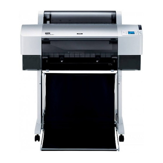
Page 31: Overall Dimensions
Note • For “rearward paper eject”, the paper exit tray is brought down toward the rear. • For “frontward paper eject”, the paper exit tray is brought down toward the front. 1,178 (When no base is mounted) 1,033 Figure 1-3. External Dimension of the Stylus Pro 7400/7800 Product Description Basic Specifications... - Page 32 EPSON Stylus Pro 7400/7800/9400/9800 Revision B 1.2.9.2 Stylus Pro 9400/9800 Overall Dimensions Outer dimensions Mass Conditions Width (W) x Depth (D) x Height (H) (mm) Conditions Mass Printer body 1,702 x 681 x 1,196 Main body (without base mounted)* Approx. 67.5kg...
-
Page 33: Accessories/Options/Consumables
Note "*1": Stylus Pro 7800, Stylus Pro 9800 (1 of each color Pk, Mk, Lk, LLk, C, M, Lc, Lm, Y) "*2": Stylus Pro 7400/7800: 1 tank, Stylus Pro 7400, Stylus Pro 9400 (2 of each color Mk, C, M, Y) Stylus Pro 9400/9800: 2 tanks... - Page 34 C13T563330 Light Cyan (Lc) C13T562530 C13T563530 Light Magenta (Lm) C13T562630 C13T563630 Yellow (Y) C13T562430 C13T563430 Table 1-25. Ink Cartridges of Stylus Pro 7400/9400 Part Number Cartridge 110 ml (Standard) 220 ml (Option) Matte Black (Mk) C13T566830 C13T567830 Cyan (C) C13T566230...
-
Page 35: External View And Parts Names
Ink Cartridge Compartment (right) Front Cover Maintenance Tank Stylus Pro 7400/7800: only one on the right side Stylus Pro 9400/9800: one each on the left and right side Figure 1-5. External View and Parts Names Product Description External View and Parts Names... -
Page 36: Control Panel
EPSON Stylus Pro 7400/7800/9400/9800 Revision B 1.4 Control Panel 1.4.1.1 LED The following table describes the LED displays and status. 1.4.1 Buttons and Functions Table 1-26. LED Color Displays Status Power Pause Paper check Ink check LED Paper Feed Enter... - Page 37 EPSON Stylus Pro 7400/7800/9400/9800 Revision B 1.4.1.2 Buttons Table 1-27. Button Functions Functions Function at the Function Button panel setting (+ Power On) Normal One Press Hold Down for Three Seconds* Power Turns the power ON or OFF Power OFF...
- Page 38 EPSON Stylus Pro 7400/7800/9400/9800 Revision B Table 1-27. Button Functions (continued) Functions Function at the Function Button panel setting (+ Power On) Normal One Press Hold Down for Three Seconds* Enter Ejects a cut sheet when it is loaded after printing Accepts the When paper is loaded during printing with no error.
-
Page 39: Panel Display
EPSON Stylus Pro 7400/7800/9400/9800 Revision B 1.4.2 Panel Display 1.4.2.1 Panel Display (LCD and LED) Note : Explanation of marks used in the following table Functions Does Not function ---: The display is in accordance with the display of printer status under operation. - Page 40 EPSON Stylus Pro 7400/7800/9400/9800 Revision B Table 1-28. Panel Display (continued) LED Status Panel Button Function Paper Printer Status Messages on the LCD Paper Cleaning Reset Power Pause Paper Enter ejection Paper feed Menu Pause Select (3 sec.) (3 sec.) (3 sec.)
- Page 41 EPSON Stylus Pro 7400/7800/9400/9800 Revision B Table 1-28. Panel Display (continued) LED Status Panel Button Function Paper Printer Status Messages on the LCD Paper Cleaning Reset Power Pause Paper Enter ejection Paper feed Menu Pause Select (3 sec.) (3 sec.) (3 sec.)
- Page 42 EPSON Stylus Pro 7400/7800/9400/9800 Revision B Table 1-28. Panel Display (continued) LED Status Panel Button Function Paper Printer Status Messages on the LCD Paper Cleaning Reset Power Pause Paper Enter ejection Paper feed Menu Pause Select (3 sec.) (3 sec.) (3 sec.)
- Page 43 EPSON Stylus Pro 7400/7800/9400/9800 Revision B Table 1-28. Panel Display (continued) LED Status Panel Button Function Paper Printer Status Messages on the LCD Paper Cleaning Reset Power Pause Paper Enter ejection Paper feed Menu Pause Select (3 sec.) (3 sec.) (3 sec.)
- Page 44 EPSON Stylus Pro 7400/7800/9400/9800 Revision B Table 1-28. Panel Display (continued) LED Status Panel Button Function Paper Printer Status Messages on the LCD Paper Cleaning Reset Power Pause Paper Enter ejection Paper feed Menu Pause Select (3 sec.) (3 sec.) (3 sec.)
- Page 45 “3.2.1 List of Panel Messages” (p.172) for more information on the error display. "*5": EPSON logo and a progress bar are displayed while running the power-on initialization sequence. "*6": Returning the printer forcedly to its normal state from a cut sheet loading error can be made by pressing the [Pause] button.
- Page 46 EPSON Stylus Pro 7400/7800/9400/9800 Revision B 1.4.2.2 Icons on the LCD Platen Gap Setting The platen gap setting made by the PLATEN GAP function in the panel setting menu Paper Source is indicated. It does not appear when using the CUSTOM PAPER setting.
- Page 47 EPSON Stylus Pro 7400/7800/9400/9800 Revision B Ink Counter and Maintenance Tank Counter Table 1-33. Ink and Maintenance Tank Counter Icons The remaining amount of ink in each cartridge and the free space of the Maintenance Tank Remaining Ink Icon Free Space Maintenance Tanks are indicated.
-
Page 48: Job Information
EPSON Stylus Pro 7400/7800/9400/9800 Revision B 1.4.3 Job Information Paper Suction The suction power to attract paper can be adjusted when the Paper Set Lever is Job Definition released, and when a paper is detected by the Rear Manual Feed sensor and the PE Each print job is defined as a “Job”* and the printer stores a variety of information... - Page 49 EPSON Stylus Pro 7400/7800/9400/9800 Revision B Job Information Note "*1": Currently reserved as 00h 00h fixed. The job information (68 bytes x 10 jobs) is stored on the NVRAM on the main "*2": As the printer is not equipped with a parallel I/F, 01h is reserved.
-
Page 50: Panel Setting
EPSON Stylus Pro 7400/7800/9400/9800 Revision B 1.4.4 Panel Setting Exiting from the Panel Setting Mode Any one of the following operations returns the printer to “ready for printing” 1.4.4.1 Outline status. Press the [Pause] button. Entering the Panel Setting Mode Press the [Paper Select ] button while the top menu is displayed. - Page 51 EPSON Stylus Pro 7400/7800/9400/9800 Revision B Panel display Printer Setup menu NOTE: Pressing the [Pause] button returns the printer to the ready status regardless which menu screen is displayed. MENU PRINTER SETUP PRINTER SETUP PRINTER SETUP Top menu TEST PRINT...
- Page 52 EPSON Stylus Pro 7400/7800/9400/9800 Revision B Test Print menu Printer Status menu MENU MENU PRINTER SETUP TEST PRINT TEST PRINT [ / ] PRINTER STATUS PRINTER STATUS TEST PRINT NOZZLE CHECK PRINTER STATUS VERSION MAINTENANCE TANK PRINTER STATUS STATUS SHEET...
- Page 53 Note : A custom paper number which is currently selected is indicated at the “nn” position. Note : Stylus Pro 7400 and Stylus Pro 9400 are not equipped with the BK Ink Change menu. The number does not appear when custom paper is not used.
- Page 54 EPSON Stylus Pro 7400/7800/9400/9800 Revision B Head Alignment menu MENU CUSTOM PAPER MAINTENANCE HEAD ALIGNMENT HEAD ALIGNMENT PAPER SELECT ALIGNMENT HEAD ALIGNMENT PAPER SELECT ALIGNMENT Product Description Control Panel...
- Page 55 EPSON Stylus Pro 7400/7800/9400/9800 Revision B 1.4.4.2 Panel Setting Mode Items List Table 1-37. Panel Setting Mode Items List Top menu (Panel display) Item menu Panel display Set value (Underline: Default) Ref. ---, 5.0~20~99.5m p.61 ROLL PAPER LENGTH ---, 15~60~300ft...
- Page 56 EPSON Stylus Pro 7400/7800/9400/9800 Revision B Table 1-37. Panel Setting Mode Items List (continued) Top menu (Panel display) Item menu Panel display Set value (Underline: Default) Ref. Firmware Version VERSION SN0xxxx.ICBS (SW0xxxx.ICBS) p.79 1st row LIGHT LIGHT BLACK xxxxxxPAGES p.79...
- Page 57 (0%, nn%, E* F, E** F, E*** F, E**** F, E*****F) MAINTENANCE XXXXXXX (XXXXXXX is any of the following) p.82 Maintenance Tank Count (Stylus Pro 7400 and Stylus Pro 9400) TANK (0%, nn%, E* F, E** F, E*** F, E**** F, E*****F) INK xxxxx.xml Consumables usage p.82...
- Page 58 EPSON Stylus Pro 7400/7800/9400/9800 Revision B Table 1-37. Panel Setting Mode Items List (continued) Top menu (Panel display) Item menu Panel display Set value (Underline: Default) Ref. Cutter XXXXXXX (XXXXXXX is any of the following) p.84 Cutter Life (0%, nn%, E* F, E** F, E*** F, E**** F, E*****F) CR MOTOR XXXXXXX (XXXXXXX is any of the following) p.84...
- Page 59 EPSON Stylus Pro 7400/7800/9400/9800 Revision B Table 1-37. Panel Setting Mode Items List (continued) Top menu (Panel display) Item menu Panel display Set value (Underline: Default) Ref. PAPER p.95 Paper Thickness (in 0.1mm units) *1 STANDARD, 0.1mm~1.5mm THICKNESS UNI-D BI-D 2 COLOR...
- Page 60 EPSON Stylus Pro 7400/7800/9400/9800 Revision B Table 1-37. Panel Setting Mode Items List (continued) Top menu (Panel display) Item menu Panel display Set value (Underline: Default) Ref. #1 MK/PK 1~5~9 p.95 #1 LLK 1~5~9 #2 MK/PK 1~5~9 BI-D ALL #2 LLK...
- Page 61 EPSON Stylus Pro 7400/7800/9400/9800 Revision B 1.4.4.3 Roll Paper Counter Setting the Warning Length of Roll Paper When the Roll Paper length is set, an asterisk (*) is displayed beside the set This menu appears when REMAINING PPR SETUP in the Maintenance mode has been set to value for two seconds and then the Roll Length Alert screen appears.
- Page 62 EPSON Stylus Pro 7400/7800/9400/9800 Revision B 1.4.4.4 Platen Gap Table 1-38. Platen Gap Settings Paper thickness Actual PG location This function allows you to select a gap between the printhead and paper (platen) from PH command Panel SN command: m2...
- Page 63 EPSON Stylus Pro 7400/7800/9400/9800 Revision B The following 5 positions are available in the actual platen gap setting. Platen Gap Setting menu Table 1-39. Actual Platen Gap Setting PLATEN GAP Position Gap width NARROW Setting STANDARD Maximum 2.6mm For thick paper WIDE 2.1mm...
- Page 64 EPSON Stylus Pro 7400/7800/9400/9800 Revision B 1.4.4.5 Page Lines 1.4.4.6 Interface This menu allows you to print or not print a page lines (cutoff lines). The page line, a This menu allows you to switch the interface setting between auto-detection, USB, black solid line with 1 dot width, cannot be printed on cut sheet media (only for roll IEEE1394, and optional interface.
- Page 65 EPSON Stylus Pro 7400/7800/9400/9800 Revision B 1.4.4.7 Code Page 1.4.4.8 Roll Paper Margin The Code Page for the printer can be switched between PC437 (extended graphics) and Margin setting for roll paper can be selected from the following settings: PC850 (multilingual).
- Page 66 EPSON Stylus Pro 7400/7800/9400/9800 Revision B If the width of image is larger than that of the specified printable area, the extended Note 1: Using the Borderless Print function, left and right margins can be set to 0. width of the image is clipped off from its right side. In such case, a vertical page line is 2: When the following patterns are printed, left and right margins are fixed to 3mm.
- Page 67 EPSON Stylus Pro 7400/7800/9400/9800 Revision B Roll Paper Margin menu 1.4.4.9 Page Size Check The printer automatically detects the width of loaded media if this function is set to PRINTER SETUP ON. Disabling this (setting it to OFF) is not recommended especially when performing...
-
Page 68: Time Out
EPSON Stylus Pro 7400/7800/9400/9800 Revision B 1.4.4.10 Paper Skew Check 1.4.4.11 Time Out When this is set to “ON”, the printer automatically detects that a paper is loaded or fed This menu allows you to select a time period for job time out from five options. When at an angle and causes a paper skew error. -
Page 69: Cutter Adjustment
EPSON Stylus Pro 7400/7800/9400/9800 Revision B 1.4.4.12 Cutter Adjustment Cutter Adjustment menu This menu is provided to adjust a position to cut top and bottom edges of media to PRINTER SETUP produce a full-bleed print on all four sides (Borderless print). So, the menu is enabled TIEM OUT only when the “Roll Auto Cut ON”... -
Page 70: Auto Nozzle Check
EPSON Stylus Pro 7400/7800/9400/9800 Revision B 1.4.4.13 Refresh Margin 1.4.4.14 Auto Nozzle Check This function is used to feed paper by the amount of “minimum cut length” and cut it The printer automatically checks nozzles for clogging before starting each print job before starting the next print job after making a 4-side borderless print. - Page 71 EPSON Stylus Pro 7400/7800/9400/9800 Revision B 1.4.4.15 Auto Cleaning 1.4.4.16 Quiet Cut The printer automatically runs a head cleaning when this is set to ON. If the “Auto The “Quiet Cut” enables the slowest cutting mode (20 CPS). The default is OFF. This Nozzle Check”...
- Page 72 Cur.PaperCount:<ddddd.d>cm Pre.PaperCount:<eeeee.e>cm C-P:<fffff.f>cm AUTO NOZZLE CHECK Figure 1-13. Auto Nozzle Check Pattern (Stylus Pro 9800) AUTO CLEANING QUIET CUT Order of colors (Stylus Pro 7400 and Stylus Pro 9400: from left) Initialize Settings menu Matte Black→Cyan→Magenta→Yellow→Matte Black→Cyan→ Magenta→Yellow PRINER SETUP...
- Page 73 (5.1-digit) <ccccc.c>: Value obtained by subtracting <bbbbb.b> from <aaaaa.a> (5.1-digit) Order of colors (Stylus Pro 7400 and Stylus Pro 9400: from left) <ddddd.d>: Paper consumption counter detected immediately before Matte Black x 2→Magenta x 2→Cyan x 2→Yellow x 2 printing the pattern (5.1-digit)
- Page 74 EPSON Stylus Pro 7400/7800/9400/9800 Revision B 1.4.4.19 Printing Status Sheet Type B : Installed - Current Setting +-----------------+- Printer Status -+---------------- The “Status Sheet” in the TEST PRINT menu allows you to print a Status Sheet (a list Platen Gap...
- Page 75 E[*****]F Production Date `02/03 `02/03 Expire Date `03/10 `03/10 Ink Life 6 month 6 month Passed 2 month 2 month Printable Sheet 120 pages 120 pages ------------------+------------------+-----------------+----------------- Figure 1-18. Status Sheet of the Stylus Pro 7400 Product Description Control Panel...
- Page 76 EPSON Stylus Pro 7400/7800/9400/9800 Revision B 1.4.4.20 Printing Job Information Note "*1": Available space in the Maintenance Tank is indicated as shown below. A job history report (up to 10 jobs) stored on the printer can be printed using the “Job 100 to 81% E∗∗∗∗∗F...
- Page 77 M xxx.xxml Y xxx.xxml xxx.xxml C2 xxx.xxml Y xxx.xxml Y2 xxx.xxml Figure 1-19. Job information print pattern (Stylus Pro 7800 / Stylus Pro 9800) Figure 1-20. Job information print pattern (Stylus Pro 7400 / Stylus Pro 9400) Product Description Control Panel...
- Page 78 EPSON Stylus Pro 7400/7800/9400/9800 Revision B 1.4.4.21 Printing Custom Paper Information Paper No.1 Custom Name : XXXXXXXXXXXXXXXXXXXXXXXXXXXXXX User-defined paper settings stored on the printer using the CUSTOM PAPER menu Platen Gap : Standard Drying Time : 10.0 sec Suction : Standard can be printed out by executing the “Custom Paper”...
-
Page 79: Firmware Version
EPSON Stylus Pro 7400/7800/9400/9800 Revision B 1.4.4.22 Firmware Version 1.4.4.23 Printable Pages The “Version” in the PRINTER STATUS menu displays the version of the installed The “Printable Pages” in the PRINTER STATUS menu displays estimated pages that firmware on the LCD panel. -
Page 80: Ink Level
EPSON Stylus Pro 7400/7800/9400/9800 Revision B Stylus Pro 7400 and Stylus Pro 9400 1.4.4.24 Ink Level The “Ink Level” in the PRINTER STATUS menu displays remaining amount of ink PRINTER STATUS per ink cartridge. VERSION PRINTABLE PAGES PRINTABLE PAGES MATTE BLACK Table 1-43. - Page 81 EPSON Stylus Pro 7400/7800/9400/9800 Revision B Ink Level Menu Stylus Pro 7800 and Stylus Pro 9800 Stylus Pro 7400 and Stylus Pro 9400 PRINTER STATUS PRINTER STATUS PRINTABLE PAGES INK LEVEL PRINTABLE PAGES INK LEVEL INK LEVEL LIGHT LIGHT BLACK...
- Page 82 EPSON Stylus Pro 7400/7800/9400/9800 Revision B 1.4.4.25 Maintenance Tank Counter 1.4.4.26 (Ink and Paper) Usage Counter The “Maintenance Tank” in the PRINTER STATUS menu displays available space in The “Usage Count” in the PRINTER STATUS menu displays a cumulative amount of the Maintenance Tank.
- Page 83 EPSON Stylus Pro 7400/7800/9400/9800 Revision B 1.4.4.27 Clear Usage Counter 1.4.4.28 Job History Clear Usage Count - INK The “Job History” displays job history report (up to 10 jobs) stored on the printer. Resets the “Ink usage counter” to 0.
- Page 84 EPSON Stylus Pro 7400/7800/9400/9800 Revision B 1.4.4.29 Total Prints CR Motor life Calculation method The “Total Prints” displays a cumulative number of printed pages by decimal number The life of the CR motor is regarded as that of the Ink Supply Tube because a up to 6-digit.
- Page 85 EPSON Stylus Pro 7400/7800/9400/9800 Revision B PF Motor life Head Unit life Calculation method Calculation method The PF motor and any other parts or components in the paper feed mechanism The total life of the unit is calculated by multiplying the guaranteed number of are not required to be replaced within the lifespan of the printer.
- Page 86 EPSON Stylus Pro 7400/7800/9400/9800 Revision B Cleaning Unit life Pressure Motor life Calculation method Calculation method The life of the cleaning unit is judged by the life of the pump motor. When The life of the Pressure Pump Unit is judged by the life of the Pressure Pump.
- Page 87 EPSON Stylus Pro 7400/7800/9400/9800 Revision B Service Life Menu 1.4.4.31 Custom Paper This function allows the user to store the user-defined paper settings up to 10. Once the PRINTER STATUS paper setting is made, the user can retrieve the setting just by specifying the assigned JOB HISTORY number.
- Page 88 EPSON Stylus Pro 7400/7800/9400/9800 Revision B Custom Paper setting handling Table 1-46. Custom Paper Settings (continued) Item Details Setting value Paper setup Operation PAPER Paper suction level to SN m1 = 05h Standard When each setting item values are set by commands, the printer follows...
- Page 89 EPSON Stylus Pro 7400/7800/9400/9800 Revision B M/W Setting List Table 1-47. M/W (Print Mode) Settings Raster M/W mode setting resolution Dot size setting Mode ID ESC (i Color Bit/ Output Panel UNIT setting DS range Remarks Restrictions number Pixel resolution...
- Page 90 EPSON Stylus Pro 7400/7800/9400/9800 Revision B Table 1-47. M/W (Print Mode) Settings(continued) Raster M/W mode setting resolution Dot size setting Mode ID ESC (i Color Bit/ Output Panel UNIT setting DS range Remarks Restrictions number Pixel resolution setting Color Horizontal...
- Page 91 EPSON Stylus Pro 7400/7800/9400/9800 Revision B Custom Paper menu * When the Custom Paper No.1 to * The "nn" indicates the specified number. 10 are used. PAPER NUMBER CUSTOM PAPER PAPER NUMBER PAPER NUMBER Setting PLATEN GAP Setting STANDARD THICKNESS PATTERN...
- Page 92 EPSON Stylus Pro 7400/7800/9400/9800 Revision B Paper thickness detection pattern Printing specifications Head speed 240cps Pattern height 64 Dot Dot size VSD2 Large A4 narrow side width Color Black Print direction Uni-D Pattern interval Upper row: Regular intervals Lower row: One of the 16 lines reflects the current PG setting. The gap between the line and the upper line becomes the center value.
- Page 93 EPSON Stylus Pro 7400/7800/9400/9800 Revision B Shifting amount of the lower lines 1.4.4.32 Cutter Replacement The following illustrates and explains the shifting amount of the lower lines The “Cutter Replacement” in the MAINTENANCE menu displays instructions for printed on the pattern assuming that the shift amount is “x” micrometers when replacing the cutter on the LCD panel in accordance with operations made by the user.
- Page 94 The set time is used for the Job Information. NOTE: The Stylus Pro 7400 and Stylus Pro 9400 are not equipped with this This time setting is disabled if the time synchronization is adopted by the TypeB function.
- Page 95 Thickness PG Settings adjustment Saved as Remarks Select the “Standard” in the “Paper Thickness” menu if the paper is EPSON Sensor Input pattern paper with thickness of 0.2 or 1.2 mm. If the paper does not fit the requirements, the thickness can be entered in increments of 0.1 mm.
- Page 96 EPSON Stylus Pro 7400/7800/9400/9800 Revision B Note "*1": [When performing Auto or Manual Bi-D Adjustment] • The printer compares the default settings and the user-defined settings, and performs the following operations if it detects no difference between them. • Prints the adjustment pattern with PG 1.6-mm setting.
-
Page 97: Head Alignment Menu
BI-D #1 BI-D 2 COLOR BI-D #2 BI-D ALL BI-D #3 *Characters in the round brackets indicate color names displayed on the Stylus Pro 7400/9400. Adjustment Value (UP) Adjustment Value (UP) Adjustment Value (UP) UNI-D #1 C (C2) UNI-D #3 LLK (MK2) - Page 98 EPSON Stylus Pro 7400/7800/9400/9800 Revision B Head Alignment adjustment patterns Adjustment pattern printing of each adjustment item Adjustment pattern print specifications Number of printing 9 Patterns (1 for each color) Adjustment pattern Bi-D 2-COLOR (#1, #2, #3) patterns height Bi-D All (#1, #2, #3)
-
Page 99: Maintenance Mode
EPSON Stylus Pro 7400/7800/9400/9800 Revision B 1.4.5 Maintenance Mode Panel display (Level structure of Maintenance Mode) OUTLINE MAINTENANCE MODE HEX DUMP HEX DUMP LANGUAGE Start Up PRINT Executes REMAINING PPR SETUP LIGHT LIGHT BLACK the operation The printer starts up in the Maintenance mode when it is turned ON with the MANUFACTURER [PAUSE] button pressed. - Page 100 EPSON Stylus Pro 7400/7800/9400/9800 Revision B MAINTENANCE MODE SETUP ITEMS Table 1-50. Maintenance Mode Setup Items Top Menu Panel Display Item Menu 1 Panel Display Item Menu 2 Panel Display Setting Values Hexadecimal Dump Printing HEX DUMP – – –...
- Page 101 EPSON Stylus Pro 7400/7800/9400/9800 Revision B Table 1-50. Maintenance Mode Setup Items(continued) Top Menu Panel Display Item Menu 1 Panel Display Item Menu 2 Panel Display Setting Values Manufacture logo MANUFACTURE "EPSON" Ink color COLOR LIGHT CYAN (MAGENTA) Ink type...
- Page 102 EPSON Stylus Pro 7400/7800/9400/9800 Revision B Table 1-50. Maintenance Mode Setup Items(continued) Top Menu Panel Display Item Menu 1 Panel Display Item Menu 2 Panel Display Setting Values Manufacture logo MANUFACTURE "EPSON" Ink color COLOR CYAN (CYAN) Ink type INK TYPE...
- Page 103 EPSON Stylus Pro 7400/7800/9400/9800 Revision B HEX DUMP UNIT Print data received by the printer is printed out in hexadecimal notation. Using this Switches the unit of length used in the panel display and pattern printing between meter function, users can check that data has been sent correctly from the computer to the and feet/inch.
- Page 104 EPSON Stylus Pro 7400/7800/9400/9800 Revision B SS (SUPERSONIC) CLEANING INK INFO MENU Executes a supersonic cleaning. (Executes CL3.) Displays the ink information recorded on the CSIC. Table 1-52. Ink Information PWR ON ROLL PPR FEED Item Explanation Specifies the paper feeding operation at power-On when the Auto Roll Cut is Off.
-
Page 105: Serviceman Mode
EPSON Stylus Pro 7400/7800/9400/9800 Revision B 1.4.6 SERVICEMAN MODE Startup The printer starts up in the SERVICEMAN MODE when it is turned ON with the [Pause], [Paper Feed ], and [Menu ] buttons hold down. OUTLINE Operation The SERVICEMAN MODE, consists of the SELF TESTING, the VIEW COUNTER,... - Page 106 PF encoder Continued to next page Note "*1": ““Anti-home side” or “Home side” is displayed with the “Maintenance Tank” on the Stylus Pro 9400/9800. They are not displayed on the Stylus Pro 7400/7800. "*2": Not displayed for the Stylus Pro 7400/7800.
- Page 107 Discharged amount of ink (G) Fire H Discharged amount of ink (H) Cutting times Cutter Solenoid operating Cut Sole frequency Continued to next page "*3": Not displayed for the Stylus Pro 7400/7800. "*4": Home side "*5": Anti-home side Product Description Control Panel...
- Page 108 EPSON Stylus Pro 7400/7800/9400/9800 Revision B Table 1-53. Self Testing Menu Items(continued) 1st Screen 2nd Screen 3rd Screen 4th Screen 5th Screen Panel Panel Panel Panel Display Description Panel Display Description Description Description Display Display Display Error0 Error 0 Error1...
- Page 109 EPSON Stylus Pro 7400/7800/9400/9800 Revision B Table 1-53. Self Testing Menu Items(continued) 1st Screen 2nd Screen 3rd Screen 4th Screen 5th Screen Panel Panel Panel Panel Display Description Panel Display Description Description Description Display Display Display PF Head Bid Bi-D adjustment Adj.
- Page 110 EPSON Stylus Pro 7400/7800/9400/9800 Revision B Panel Function Check TEST MENU This function allows you to check the operation of the buttons, LCD and LEDs on the Version Display panel. To exit the panel function check, press the [Pause] switch twice.
- Page 111 • 00: Paper thickness is 0.3mm or less • 10: Paper thickness is 0.4mm to 0.8mm NOTE 1: “Paper3” (paper suction fan 3) is not displayed on the Stylus Pro 7400/ 7800. • 11: Paper thickness is more than 0.9mm 2: Paper suction fan located at the Carriage home side is referred to as •...
- Page 112 EPSON Stylus Pro 7400/7800/9400/9800 Revision B Electric Actuator 2 Fatal errors of up to 7 maintenance items recorded as history can be checked. (CPU This allows you to check the operation of the Cutter Solenoid, Pump motor, Regulator error is not recorded.) Solenoid, and Pressure motor.
- Page 113 EPSON Stylus Pro 7400/7800/9400/9800 Revision B Paper Thickness Sensor Adjustment ADJUSTMENT The sensor can be adjusted. Paper Suction Function The meaning of the displayed numbers is as follows: Operation check 00: Paper thickness 0.3mm or less The two or three paper suction fans can be checked individually if they work 10: Paper thickness is within 0.4mm to 0.8mm...
- Page 114 EPSON Stylus Pro 7400/7800/9400/9800 Revision B Head Nozzle Check Horizontal alignment check • The pattern is printed in the order of E, F, G, H, D, C, B, and A row from the This function allows you to check the nozzles by a printed pattern if they discharge ink left.
- Page 115 The position of each ink pad on the platen can be detected and adjusted. Ink Color Nozzle Stylus Pro 7800, Stylus Pro 9800 Stylus Pro 7400, Stylus Pro 9400 Light Light Black Matte Black Light Magenta Print mode: 360dpi, Uni-D, 320cps, VSD1, Large...
- Page 116 EPSON Stylus Pro 7400/7800/9400/9800 Revision B Platen Position Check Rear Sensor Position Adjustment The position of each ink pad on the adjusted platen can be checked. Rear sensor position setting in the firmware can be adjusted to detect cut sheet length accurately (to ensure the maximum printable area on the bottom of the sheet).
- Page 117 Table 1-57. Nozzle Row and Ink Color Ink Color PF Head Alignment Figure 1-31. Check Pattern Nozzle Row Stylus Pro 7800, Stylus Pro 9800 Stylus Pro 7400, Stylus Pro 9400 Light Light Black Matte Black Magenta Yellow Product Description Control Panel...
- Page 118 Prints Figure 1-34 in VSD1 mode Uni-D pattern (VSD1) The Stylus Pro 9400/9800: three pattern blocks for each waveform The Stylus Pro 7400/7800: two pattern blocks for each waveform Prints Figure 1-34 in VSD2 mode Uni-D pattern (VSD2) Figure 1-33. Gap Adjustment (Uni-D) Pattern...
- Page 119 PK: AVE____ C: AVE____ M: AVE____ Y: AVE____ The Stylus Pro 9400/9800: three pattern blocks for each waveform Stylus Pro 9800 Above the The Stylus Pro 7400/7800: two pattern blocks for each waveform pattern Stylus Pro 7400, C: AVE____ C-2: AVE____ Y: AVE____ Y-2: AVE____ Figure 1-35.
- Page 120 EPSON Stylus Pro 7400/7800/9400/9800 Revision B Paper Skew Check Band Feed and Top & Bottom Margins Adjustment Loaded paper is fed by the set amount (one bus) at one time. Positions of the paper An amount (length) of paper feeding at a time (Band feed), and the top, bottom, and edge before and after the feeding is detected by sensors and checked if they are the side margins can be adjusted.
- Page 121 EPSON Stylus Pro 7400/7800/9400/9800 Revision B Table 1-62. Positions of Printed Lines Ink-mark Sensor Position Adjustment 360dpi-based On a millimeter 360dpi-based On a millimeter The position of the Ink-mark sensor can be adjusted and checking the sensor for Intervals basis...
- Page 122 EPSON Stylus Pro 7400/7800/9400/9800 Revision B [PG=1.2] [Count] MK:5 C :0 M :0 Y :0 LLk:0 Lm:0 LC:0 Lk:0 [Position] MK : ( 0), ( 0), ( 0), ( 0), ( 0), ( 0), ( 0), ( 0), ( 0), (...
- Page 123 EPSON Stylus Pro 7400/7800/9400/9800 Revision B 1.4.6.2 Counter Display Menu (VIEW COUNTERS) Cutter Life Counter This menu displays the counter value of each unit/part. Displays cutter life counter value. Cutter life counter is counted every cut operation. Cutter life counter value is initialized (initial value 0) when replacing cutter.
- Page 124 EPSON Stylus Pro 7400/7800/9400/9800 Revision B Pressure Motor Life Counter Displays life counter of the Pressure Pump motor. Head Unit Life Counter Value Display (A Row - H Row) Displays life counter of each nozzle from A row to H row. Head unit life counter is counted every ink discharging.
- Page 125 EPSON Stylus Pro 7400/7800/9400/9800 Revision B 1.4.6.3 Maintenance Information Menu (MAINT INFO) All the life counters, and other various information on usage conditions stored on the NVRAM can be displayed on the LCD panel. Table 1-64. MAIN INFO Menu Items...
- Page 126 Note • The number of executions of the initial ink charge is counted when CL1 is performed at the beginning of the charging sequence. • The “L” (anti-home side) and “R” (home side) are displayed on the Stylus Pro 9400/9800 only. They are not displayed on the Stylus Pro 7400/7800.
- Page 127 EPSON Stylus Pro 7400/7800/9400/9800 Revision B Table 1-64. MAIN INFO Menu Items (continued) Top menu 1st hierarchy 2nd hierarchy Settings Unit Item Item Description Item Description Cumulative amount of ink consumed Slot 1 EPSON ink <nnnnnnnnnn> Cumulative amount of ink consumed...
- Page 128 EPSON Stylus Pro 7400/7800/9400/9800 Revision B Table 1-64. MAIN INFO Menu Items (continued) Top menu 1st hierarchy 2nd hierarchy Settings Unit Item Item Description Item Description Date and time of ink replacement (Slot 1) <YY><MM><DD> Date and time Ink vendor name (Slot 1) <xxxxxxxxxxxxxxxxx>...
- Page 129 EPSON Stylus Pro 7400/7800/9400/9800 Revision B Table 1-64. MAIN INFO Menu Items (continued) Top menu 1st hierarchy 2nd hierarchy Settings Unit Item Item Description Item Description Date and time of ink replacement (Slot 6) <YY><MM><DD> Date and time Ink vendor name (Slot 6) <xxxxxxxxxxxxxxxxx>...
- Page 130 EPSON Stylus Pro 7400/7800/9400/9800 Revision B Table 1-64. MAIN INFO Menu Items (continued) Top menu 1st hierarchy 2nd hierarchy Settings Unit Item Item Description Item Description Number of settings of roll paper <nnnnnnnnn> Number of times Number of settings of cut sheet (manual feed) <nnnnnnnnn>...
- Page 131 EPSON Stylus Pro 7400/7800/9400/9800 Revision B Table 1-64. MAIN INFO Menu Items (continued) Top menu 1st hierarchy 2nd hierarchy Settings Unit Item Item Description Item Description Printable length Paper width 1 <nnnnnnnnn> Number of ejections of paper Paper width 1 <nnnnnnnnn>...
- Page 132 EPSON Stylus Pro 7400/7800/9400/9800 Revision B Table 1-64. MAIN INFO Menu Items (continued) Top menu 1st hierarchy 2nd hierarchy Settings Unit Item Item Description Item Description Number of times the print mode is specified 1 2880-1440 4PASS Uni-D <nnnnnnnnn> Number of times...
- Page 133 EPSON Stylus Pro 7400/7800/9400/9800 Revision B Table 1-64. MAIN INFO Menu Items (continued) Top menu 1st hierarchy 2nd hierarchy Settings Unit Item Item Description Item Description Number of changes of the platen gap setting <nnnnnnnnn> Number of times Number of changes of roll paper margin setting <nnnnnnnnn>...
- Page 134 EPSON Stylus Pro 7400/7800/9400/9800 Revision B Table 1-64. MAIN INFO Menu Items (continued) Top menu 1st hierarchy 2nd hierarchy Settings Unit Item Item Description Item Description Service call error type ever occurred 1 <xxxxxxxx> Error code Date and time of occurrence of the error 1 <YY><MM><DD>...
- Page 135 EPSON Stylus Pro 7400/7800/9400/9800 Revision B Table 1-64. MAIN INFO Menu Items (continued) Top menu 1st hierarchy 2nd hierarchy Settings Unit Item Item Description Item Description Normal error type ever occurred 1 <xxxxxxxx> Error code Date and time of occurrence of the error 1 <YY><MM><DD>...
-
Page 136: Mib Function
1.4.7 MIB Function 1.4.8 Function to Prevent Irregular Printing The Stylus Pro 7400/7800 and the Stylus Pro 9400/9800 are compatible with the two Forced cancel of print job types of MIB described in the tables below. This allows you to see the printer... -
Page 137: Initialization
EPSON Stylus Pro 7400/7800/9400/9800 Revision B 1.4.9 Initialization 1.4.10 Default Setup Values The printer performs initialization operation by the following method. 1.4.10.1 Operation Default Setting 1.4.9.1 Hardware Initialization Default Status Default setup values in initialization operation are as follows. The parameters for... -
Page 138: Controller
EPSON Stylus Pro 7400/7800/9400/9800 Revision B 1.5 Controller CPU: SH7709S 144 MHz Code ROM: 2 MB Font ROM: None RAM: Stylus Pro 7400/7800: 64 MB Stylus Pro 9400/9800: 128 MB Interface IEEE1394 USB (HS, FS) Type-B Interface Hitachi HI7700 (µITRON 3.0 compatible) -
Page 139: Interface
EPSON Stylus Pro 7400/7800/9400/9800 Revision B 1.6 Interface SIGNAL ASSIGNMENT AND SIGNAL DEFINITION OF INPUT CONNECTOR PIN Table 1-66. Signal Assignment and Signal Definition of 1.6.1 USB interface Input Connector Pin (USB (FS)) Pin No. Signal name In/Out Function description SPECIFICATION Cable power. -
Page 140: Ieee1394 Interface
EPSON Stylus Pro 7400/7800/9400/9800 Revision B 1.6.2 IEEE1394 Interface PROTOCOL SB-2 (ANSI NCITS 325-1998) compliant FEATURES EP-PPDT (Based on IEEE 1394.3 specification) IEEE Std.1394-1995,1394a-2000 compliant 400 Mbps 1 port (Standard 6-pin receptacle) Power Class: POWER_CLASS=000 Node does not need power and does not repeat power... -
Page 141: Optional Interface
EPSON Stylus Pro 7400/7800/9400/9800 Revision B 1.6.3 Optional Interface REPLY FOR OPTION COMMAND Type-B interface (level 3, MIB, 1200mA type) is supported. Table 1-68. Reply List Option command REPLY MESSAGE Command name Reply-A Reply-B number Main-Type No-operation Accept None Stylus Pro 7400/7800... - Page 142 EPSON Stylus Pro 7400/7800/9400/9800 Revision B SUPPORTED MAIN COMMAND AND SENDING TIMING TYPE-B LEVEL 3 PACKET MODE Communication between Type-B I/F card and Printer corresponds to Type-B Level 3 Table 1-69. Supported Main Command and Sending Timing (Packet Mode) Communication Specification. (IEEE P1284.4 (Draft 1.50) compliant)
-
Page 143: Chapter 1 Product Description
EPSON Stylus Pro 7400/7800/9400/9800 Revision B 1.6.4 Received Buffer Full Operation Supported Packet Apply the following communication packet. If the receiving buffer free space becomes less than 32Kbytes when data is being Table 1-71. Supported Packet received from the USB interface or IEEE1394 interface, and there are no errors... -
Page 144: Optional Units And Consumables
Stylus Pro 7800, Stylus Pro 9800 Photo black, magenta, light magenta, cyan, light cyan, yellow, light black, matte black, light light black Stylus Pro 7400, Stylus Pro 9400 Matte black, magenta, cyan, yellow Product Description Optional Units and Consumables... -
Page 145: Cleaning Cartridge
EPSON Stylus Pro 7400/7800/9400/9800 Revision B 1.7.2 Cleaning Cartridge 1.7.3 Conversion Cartridge Type: Exclusive cleaning cartridge Type: Exclusive cartridge for ink change (not to be used as an ink cartridge) Dimension: Dimension: 110 ml / 220 ml (W): 27.1 mm x (D): 185 mm x (H): 107 mm 110 ml / 220 ml (W): 27.1 mm x (D): 185 mm x (H): 107 mm... -
Page 146: Maintenance Tank
The Stylus Pro 9400/9800 have two Maintenance Tanks on their lower left and right sides respectively. The Stylus Pro 7400/7800 have one Maintenance Tank on their lower right side. The tank can be replaced by the user when it becomes full. -
Page 147: Chapter 2 Operating Principles
C H A P T E R OPERATING PRINCIPLES... -
Page 148: Overview
EPSON Stylus Pro 7400/7800/9400/9800 Revision B 2.1 Overview This chapter explains the print mechanism and operating principles for the EPSON Stylus Pro 7400/7800/9400/9800. The explanation is composed as follows: 2.2 Print Mechanism Components (p.149) 2.2.1 Print Mechanism (Print Head) (p.150) 2.2.2 Carriage (CR) Mechanism (p.151) -
Page 149: Print Mechanism Components
EPSON Stylus Pro 7400/7800/9400/9800 Revision B 2.2 Print Mechanism Components Table 2-1. Printer Mechanism Components Drive Refer Part Explanation The major electrical parts used in the printer mechanism of this printer are as shown voltage below. Hereafter, we will explain each printer mechanism focusing on these parts. -
Page 150: Print Mechanism (Print Head)
2.258mm 2.258mm 2.258mm 2.258mm 64/720inch 64/720inch 64/720inch 64/720inch Stylus Pro 7400/7800/9400/9800 employ a single print head which incorporates both 7.620mm 7.620mm 7.620mm functions for black and color as the previous model; Stylus Pro 7600/9600. 216/720inch 216/720inch 216/720inch The print head incorporates a thermistor. According to the temperature around the head... -
Page 151: Carriage (Cr) Mechanism
Carriage To ensure reliable and high-precision printing on wide-width paper (Stylus Pro 9400/ 9800 support B0 size, and Stylus Pro 7400/7800 support A1 size), the printer is P EDGE Sensor equipped with a unique carriage mechanism which enables stable and high-precision movement of the on-carriage head. - Page 152 EPSON Stylus Pro 7400/7800/9400/9800 Revision B Ink Mark Sensor CARRIAGE MOVING UNIT This is a diffuse reflectance photosensor which functions in the same way as the multi sensor used on the previous models; Stylus Pro 4000/4400/4800. The sensor The carriage is installed on the square pipe - CR shaft (guide rail) made of extruded located on the rear of the carriage unit performs emitting light and responding to aluminum via roller type bearings as the previous model;...
- Page 153 EPSON Stylus Pro 7400/7800/9400/9800 Revision B PLATEN GAP ADJUSTMENT UNIT CR Guide Rail In order to maintain the print precision, it is necessary to maintain the carriage (= head) Bearing (Roll Type) mounting position so that it is always a constant distance from the surface of the paper.
- Page 154 EPSON Stylus Pro 7400/7800/9400/9800 Revision B PG HP Sensor (Platen Gap HP Detection) A shield is attached on the shaft of the PG slide gear (on the carriage) which works Start with the pump motor. The sensor detects the edge of the shield to adjust height of the print head.
- Page 155 EPSON Stylus Pro 7400/7800/9400/9800 Revision B P EDGE (Paper Width Detection) Sensor Carriage This sensor, mounted at the left-bottom side of the carriage unit, detects paper edges by moving the carriage. It detects four points of paper edges, namely, left and right points on the front edge and a front point on the left and right edges of the paper.
-
Page 156: Operating Principles
EPSON Stylus Pro 7400/7800/9400/9800 Revision B Paper size detection sequence (left and right edges) Note "*1":Printing area MAX position · Stylus Pro 9400/9800 Error display: Left and right edge detection start 1,257.91mm + 7.0mm (Reserved width) Set the paper correctly ·... - Page 157 EPSON Stylus Pro 7400/7800/9400/9800 Revision B Paper size detection sequence (front edge) Note "*1":Paper left upper detection Front edge detection start position = Paper left edge Conditions: position + 27.5 mm The CR moves onto Fl_Box. (320CPS) For execution of this processing, the paper level threshold value must be "*2":PF maximum travel =...
- Page 158 EPSON Stylus Pro 7400/7800/9400/9800 Revision B Simplified detection sequence for left and right edges (skew check) Left and right edge detection start When the paper width detection function is turned off, left and right edge Paper absence detected Edge sensor LED lights up detection (skew check) is not carried out.
- Page 159 EPSON Stylus Pro 7400/7800/9400/9800 Revision B Cutter Solenoid Cutter Solenoid Carriage This DC solenoid controls the cutting pressure of the roll paper cutter. It also unlocks the carriage. Roll Paper The function can be set to On or Off using the Panel buttons.
-
Page 160: Paper Feed Assembly
EPSON Stylus Pro 7400/7800/9400/9800 Revision B 2.2.3 Paper Feed Assembly PF motor The PF motor is a DC motor. The slit of the loop scale mounted on the Grid Roller This printer uses friction feed to carry out highly precise feeding of roll paper and cut is read by the PF_ENC sensor and the output pulse is fed back to control the sheets, and comprises a unique paper feed mechanism. - Page 161 The printer is equipped with suction fans in the front lower space. The space behind the Paper Guide L is divided into 3 compartments (Stylus Pro 7400/7800 are divided into 2), and one fan is mounted in each compartment. Paper on the Paper Guide L1 and L2 is firmly attracted to the guides by air flow created by the fans.
- Page 162 EPSON Stylus Pro 7400/7800/9400/9800 Revision B The sensors used in the paper feeding mechanism are explained below. P REAR sensor This is a photo-reflective sensor located on the backside of the H Top Cover. It detects paper absence by detecting the rear edge of the paper, and detects the leading edge of paper when the paper is loaded to let the printer start the paper setting operation such as attracting the paper to the paper guides.
-
Page 163: Cleaning Mechanism
Major differences in the cleaning mechanism between the previous Stylus Pro 7600/ (Drive Mode) Revolving Speed Amount (2-2 phase conversion) 9600 and the Stylus Pro 7400/7800/9400/9800 are pressure pump and the number of Low speed (IS4) 0.55 rev/sec 0.3g/sec 182 Hz flushing boxes and maintenance tanks. - Page 164 EPSON Stylus Pro 7400/7800/9400/9800 Revision B Table 2-7. Explanation of Operation Operation Explanation Carriage (CR) Lock • This is the carriage stop position when the power is Off. • The time when the carriage is in the standby position (home position) with the power ON and with no paper loaded and no print data to print.
-
Page 165: Ink Supply Mechanism
EPSON Stylus Pro 7400/7800/9400/9800 Revision B 2.2.5 Ink Supply Mechanism Pressure Pump The Stylus Pro 7800/9800 have two Ink Holders (I/H) on left and right side of them and each I/H carries 8 cartridges for 8 colors. A projection and unique marking are... -
Page 166: Others
EPSON Stylus Pro 7400/7800/9400/9800 Revision B 2.2.6 Others Panel Unit COVER SENSOR In order to detect whether the front cover on the lower front of this printer is open or closed, a cover sensor is mounted on the printer on the left side where the front cover opens and closes. -
Page 167: Outline Of Power Supply Circuit Board
A3958 CR Motor Drivers IC • PWM constant current drive control A6628 Pump Motor/Pressure Motor Drivers IC Note "*": Stylus Pro 7400/7800: IC2/9 only (64MByte) Stylus Pro 9400/9800: IC2/9 and IC7/10 (128MByte) Operating Principles Outline of Power Supply Circuit Board... -
Page 168: Outline Of Power Supply Circuit Board
EPSON Stylus Pro 7400/7800/9400/9800 Revision B 2.4 Outline of Power Supply Circuit Board There are three control signals between the C594 MAIN Board and the Power Supply Circuit Board as shown in the table below. The 100 V AC power from the wall outlet is supplied via the power cable, an accessory Table 2-10. -
Page 169: Colorimetric Calibration (Color Id) Overview
EPSON Stylus Pro 7400/7800/9400/9800 Revision B 2.5 Colorimetric Calibration (Color ID) Overview Main Unit This printer employs “Colorimetric Calibration (Color ID)” to correct unit-to-unit variations in color. “Colorimetric Calibration (Color ID)” corrects not only the weight of ink droplets Printhead... -
Page 170: Chapter 3 Troubleshooting
C H A P T E R TROUBLESHOOTING... -
Page 171: Overview
EPSON Stylus Pro 7400/7800/9400/9800 Revision B 3.1 Overview When handling the lithium battery used for backup of the RTC on W A R N I N G the Main Board, strictly follow the safety instructions given in This section explains the basic procedure for troubleshooting problems on the printer “4.1.1 Precautions”... -
Page 172: Troubleshooting Based On Panel Messages
EPSON Stylus Pro 7400/7800/9400/9800 Revision B 3.2 Troubleshooting based on Panel Messages The printer runs diagnostic checks on itself according to various conditions detected by sensors. If an error condition is detected as a result of the self-diagnosis, the printer displays the corresponding error message on its LCD panel. - Page 173 EPSON Stylus Pro 7400/7800/9400/9800 Revision B Table 3-1. List of Panel Messages (continued) LED Indication Panel Message Printer Condition Reference Pages Power Pause Ink Check Paper Check PAPER ERROR The paper is not loaded correctly. Flashing p.182 LOAD PAPER PROPERLY...
- Page 174 EPSON Stylus Pro 7400/7800/9400/9800 Revision B Table 3-1. List of Panel Messages (continued) LED Indication Panel Message Printer Condition Reference Pages Power Pause Ink Check Paper Check NO CARTRIDGE No ink cartridge is installed. p.185 INSTALL INK CARTRIDGE MAINTENANCE TANK FULL The Maintenance Tank on the left side of the printer is full.
- Page 175 EPSON Stylus Pro 7400/7800/9400/9800 Revision B Table 3-1. List of Panel Messages (continued) LED Indication Panel Message Printer Condition Reference Pages Power Pause Ink Check Paper Check INK LEVER The left ink lever is released.* p.185 LOWER THE LEFT INK...
- Page 176 EPSON Stylus Pro 7400/7800/9400/9800 Revision B Table 3-1. List of Panel Messages (continued) LED Indication Panel Message Printer Condition Reference Pages Power Pause Ink Check Paper Check NO MAINTENANCE TANK The Maintenance Tank is not installed on the printer. p.187...
- Page 177 EPSON Stylus Pro 7400/7800/9400/9800 Revision B Table 3-2. List of Service Call Errors Table 3-2. List of Service Call Errors Error Code Description Reference Pages Error Code Description Reference Pages 00010040 Printing position error p.199 00000101 The CR Motor reached its end of life.
-
Page 178: Remedies For Warning Messages
EPSON Stylus Pro 7400/7800/9400/9800 Revision B 3.2.2 Remedies for Warning Messages MAINTENANCE REQUEST XXXX When a Warning error occurs, the printer displays a Warning message instead of Description “READY” or “PRINTING” messages, however, it does not interfere with printing A maintenance is required. - Page 179 EPSON Stylus Pro 7400/7800/9400/9800 Revision B Remedy NNNN Cause of the Error Parts or Components need to be Replaced Remedies 0002 The number of carriage movement cycles reached the specified value. See “ Service Call 00000101 (p.188)”. “ Service Call 00000101 (p.188)”.
- Page 180 EPSON Stylus Pro 7400/7800/9400/9800 Revision B PAPER LOW Item Description Description The remaining amount of loaded paper is low. LED Indication Paper Check LED: Flashing Cause This occurs when the REMAINING PPR SETUP in the Maintenance mode is set to “ROLL” and the counter becomes lower than the preset near-end value.
-
Page 181: Remedies For Error Messages
EPSON Stylus Pro 7400/7800/9400/9800 Revision B 3.2.3 Remedies for Error Messages SENSOR ERROR LOAD DIFFERENT PAPER When an error occurs, the printer displays the error message instead of “READY” or “PRINTING” messages. Description Remedy The following tables explains the error messages and remedies. - Page 182 EPSON Stylus Pro 7400/7800/9400/9800 Revision B BORDERLESS ERROR PAPER ERROR LOAD CORRECT SIZE PAPER LOAD PAPER PROPERLY Description Remedy Description Remedy The printer cannot perform borderless Release the Paper Set Lever to correct the The paper is not loaded correctly 1.
- Page 183 EPSON Stylus Pro 7400/7800/9400/9800 Revision B PAPER SKEW COMMAND ERROR LOAD PAPER PROPERLY CHECK DRIVER SETTINGS Description Remedy Description Remedy The paper is loaded at an angle/Cut sheet Release the Paper Set Lever to reset the paper Command Error Cancel the print job and press the [Pause]...
- Page 184 EPSON Stylus Pro 7400/7800/9400/9800 Revision B PAPER SETTING ERROR CONVERSION CRTG LIFE LOAD ROLL PAPER REPLACE CONVERSION CRTG WITH A NEW ONE Description Remedy Description Remedy The roll paper is not set correctly. If the loaded paper type is different from the...
- Page 185 Replace the ink cartridge with the correct one. MAINTENANCE TANK NEAR FULL Or the printer can recover from the error by The installed ink cartridge is not the EPSON REPLACE THE (LEFT (RIGHT) SIDE) MAINTENANCE TANK pressing the [Pause] button.
- Page 186 EPSON Stylus Pro 7400/7800/9400/9800 Revision B COVER OPEN LEVER RELEASED CLOSE COVER LOWER THE PAPER SET LEVER Description Remedy Description Remedy The front cover is open. Close the front cover. The paper set lever is released during printing. The front cover is open.
- Page 187 EPSON Stylus Pro 7400/7800/9400/9800 Revision B PAPER JAM F/W INSTALL ERROR REMOVE PAPER UPDATE FAILED RESTART THE PRINTER Description Remedy Description Remedy A paper jam occurred. Release the Paper Set Lever, open the front cover and remove the jammed paper.
-
Page 188: Remedies For Service Call Errors
Life end of the CR Motor (includes the Ink Tubes) Explanation The number of Carriage movement cycles reached the specified upper limit. Stylus Pro 7400/7800: 3,700,000 cycles Stylus Pro 9400/9800: 6,300,000 cycles If the printer is used continuously ignoring the error, it may cause the following defective conditions. - Page 189 EPSON Stylus Pro 7400/7800/9400/9800 Revision B Remedy SERVICE CALL 00010000 Check the life count of the CR Motor in the “1.4.4 Panel Setting” (p.50). Description Press the [Menu] button → PRINTER STATUS menu - PF Encoder check error SERVICE LIFE → CR MOTOR.
- Page 190 EPSON Stylus Pro 7400/7800/9400/9800 Revision B SERVICE CALL 00010001 SERVICE CALL 00010002 Description Description The PF Motor is out-of-step. Overcurrent occurred on the PF Motor. Explanation Explanation The printer causes this error and stops operation if it cannot detect the specified-...
- Page 191 EPSON Stylus Pro 7400/7800/9400/9800 Revision B SERVICE CALL 00010003 SERVICE CALL 00010004 Description Description The PF Motor out of position time-out error CR Encoder check error Explanation Explanation The printer causes this error and stops operation if it detects that the paper could...
- Page 192 EPSON Stylus Pro 7400/7800/9400/9800 Revision B SERVICE CALL 00010005 SERVICE CALL 00010007 Description Description CR Motor is out of step. The CR Motor out of position time-out error Explanation Explanation The printer causes this error and stops operation if it cannot detect the specified-...
- Page 193 EPSON Stylus Pro 7400/7800/9400/9800 Revision B SERVICE CALL 00010008 SERVICE CALL 0001000A Description Description Servo interrupt watchdog time-out error Carriage home position detection error Explanation Explanation The printer causes this error and stops operation if it detects a watchdog time-out...
- Page 194 EPSON Stylus Pro 7400/7800/9400/9800 Revision B SERVICE CALL 0001000C SERVICE CALL 00010014 Description Description PG home position detection error Failure of pressurizing Explanation Explanation The printer causes this error and stops operation if it cannot detect the PG home The printer causes this error and stops operation if it detects an abnormal condition...
- Page 195 EPSON Stylus Pro 7400/7800/9400/9800 Revision B SERVICE CALL 0001001B SERVICE CALL 0001001D Description Description Head driver (TG) temperature error CR servo parameter error Explanation Explanation The printer causes this error and stops operation if it detects an abnormal internal The printer causes this error and stops operation when it detects that a voltage temperature of the printhead by the thermistor in the head while performing beyond the prescribed range is output to the CR Motor.
- Page 196 EPSON Stylus Pro 7400/7800/9400/9800 Revision B SERVICE CALL 0001001E SERVICE CALL 00010020 Description Description PF servo parameter error CSIC reading/writing error Explanation Explanation The printer causes this error and stops operation when it detects that a voltage The printer causes this error and stops operation if it cannot load the information beyond the prescribed range is output to the PF Motor.
- Page 197 EPSON Stylus Pro 7400/7800/9400/9800 Revision B SERVICE CALL 00010026 SERVICE CALL 00010028 Description Description RTC communication error Head error Explanation Explanation The printer causes this error and stops operation when it detects that the RTC The printer causes this error and stops operation when it detects an undefined NMI circuit on the C594 Main Board malfunctions (operates in test mode).
- Page 198 EPSON Stylus Pro 7400/7800/9400/9800 Revision B SERVICE CALL 00010035 SERVICE CALL 00010038 Description Description Pump phase detection error Transistor thermistor error Possible Causes Possible Causes A position of the pump cannot be detected after the Pump Motor rotates the The transistor thermistor is faulty.
- Page 199 EPSON Stylus Pro 7400/7800/9400/9800 Revision B SERVICE CALL 0001003F SERVICE CALL 00020000 Description Description The Pressure Motor reached its end of life. NVRAM error Possible Causes Explanation The cumulative number of steps of the Pressure Motor reached the prescribed The printer causes this error and stops operation when it detects that parameters upper limit.
- Page 200 EPSON Stylus Pro 7400/7800/9400/9800 Revision B SERVICE CALL 00020003 SERVICE CALL 0002000B Description Description Boot program sum error The internal memory is insufficient. Explanation Explanation The printer causes this error and stops operation when it detects that the boot This error occurs when the cache area is judged as insufficient. The cache program of the firmware is corrupted.
- Page 201 EPSON Stylus Pro 7400/7800/9400/9800 Revision B SERVICE CALL 0EXXXXXX SERVICE CALL 10000100 Description Description A time-lag of the RTC timer CPU address error (misalignment of storing) Explanation Possible Causes This error occurs when the printer failed to communicate with the RTC chip on the Board failure Main Board.
- Page 202 EPSON Stylus Pro 7400/7800/9400/9800 Revision B SERVICE CALL 100001A0 SERVICE CALL 100005C0 Description Description CPU slot undefined command exception error CPU DMA address error Possible Causes Possible Causes CPU cold soldering Board failure Malfunction of the program, Failed to generate commands for the printer...
-
Page 203: Troubleshooting Based On Printed Result
EPSON Stylus Pro 7400/7800/9400/9800 Revision B 3.3 Troubleshooting based on Printed Result Printing Nozzle Check Pattern (Test Print Menu) (p.72) Print a nozzle check pattern. (Panel Setting → TEST PRINT → NOZZLE CHECK) This section describes the major print quality troubles and provides troubleshooting procedure for each of the trouble. - Page 204 EPSON Stylus Pro 7400/7800/9400/9800 Revision B INCONSISTENCIES IN DENSITY, BLURRING, OR UNEXPECTED SMUDGES ON THE PRINTED SIDE COLORS When smudges caused by the head or etc. appear on printed side, perform the When a print quality trouble such as inconsistencies in density, blurring images, following items.
- Page 205 EPSON Stylus Pro 7400/7800/9400/9800 Revision B SMUDGES ON THE BACKS OF PAGES HORIZONTAL WHITE OR BLACK STREAKS When ink smudges appear on the backs of pages, perform the following items. When white or black streaks appear on the printed images in the Carriage movement direction, check the following items.
- Page 206 EPSON Stylus Pro 7400/7800/9400/9800 Revision B VERTICAL BANDS When bands (inconsistencies in density, or partly grainy) appear on the printed images in the paper feeding direction, check the following items. Bi-D Adjustment Carry out the Bi-D Adjustment using any one of the following tools.
-
Page 207: Chapter 4 Disassembly & Assembly
C H A P T E R DISASSEMBLY & ASSEMBLY... -
Page 208: Overview
Wide models; Stylus Pro 9400/9800. The procedures for the Narrow This printer is equipped with a lithium battery. When handling models; Stylus Pro 7400/7800 are given under the heading the lithium battery, the following precautions should be “CHECK POINT” only when they differ from those of the Wide followed. - Page 209 Be careful not to hit it against metal parts of the printer as it can be easily damaged. • Stylus Pro 7400/7800: 49 kg (two or more persons are required) When you have to remove any parts or components that are...
-
Page 210: Recommended Tools
4.1.2 Recommended Tools 4.1.3 Recommended Screws To protect this product from damage, use the tools indicated in the following table. The following table indicates the screws used in the EPSON Stylus Pro 7400/7800/ 9400/9800 Printers. Table 4-1. Specified Tools Table 4-2. Recommended Screws... - Page 211 EPSON Stylus Pro 7400/7800/9400/9800 Revision B Table 4-2. Recommended Screws Name Color Definition C.B.P. M3x6 Silver Phillips Bind Head P-tite Screw C.P.S.(S-P2) M3x5 Silver Phillips Pan Head S-tite Screw with Spring Lock Washers and Plane Washer 2 C.P.S.(S-P2) Silver Phillips Pan Head S-tite Screw with Spring Lock Washers M2.6x6...
-
Page 212: Disassembly Procedure
EPSON Stylus Pro 7400/7800/9400/9800 Revision B 4.2 Disassembly Procedure Disassembling the frame and some components of the printer is C A U T I O N prohibited because they are assembled with precise measurements in 1/100 mm unit at the factory. Parts or components allowed to be disassembled/reassembled are listed with there part numbers on “Parts List”... - Page 213 EPSON Stylus Pro 7400/7800/9400/9800 Revision B START PANEL ASSY. (p.220) Spindle (p.219) H TOP COVER ASSY. (p.221) Maintenance Tank (p.217) Maintenance Tank (p.217) Spindle (p.219) H TOP COVER ASSY. (p.221) Ink Cartridges (p.216) H TOP COVER ASSY. (p.221) BOARD ASSY., SUB (p.236) I/H COVER R ASSY.
-
Page 214: Basic Operations
EPSON Stylus Pro 7400/7800/9400/9800 Revision B 4.2.1 Basic Operations Protective Metal Plate CARRIAGE ASSY. 4.2.1.1 Protective metal plate Open the FRONT COVER ASSY. Remove the screw that secures the protective metal plate on the left side of the CARRIAGE ASSY. and remove the plate. - Page 215 EPSON Stylus Pro 7400/7800/9400/9800 Revision B 4.2.1.2 Unlocking/Locking the CARRIAGE ASSY. Right Side of the Printer UNLOCKING THE CARRIAGE ASSY. CARRIAGE ASSY. Open the FRONT COVER ASSY. Press the CUTTER CAP and unlock the CARRIAGE ASSY. See Figure 4-4. CUTTER CAP Figure 4-4.
-
Page 216: Consumables
EPSON Stylus Pro 7400/7800/9400/9800 Revision B 4.2.2 Consumables KNOB, I/C, LOCK LEVER; C593 4.2.2.1 Ink Cartridges Open the I/H COVER R and the I/H COVER L. See Figure 4-7. Raise the two KNOB, I/C, LOCK LEVER; C593 to unlock the Ink Cartridges. - Page 217 EPSON Stylus Pro 7400/7800/9400/9800 Revision B 4.2.2.2 Maintenance Tank When removing the Maintenance Tank in the next step, be sure not C A U T I O N to touch the IC chip on the tank. Doing so may cause a malfunction of the printer.
- Page 218 EPSON Stylus Pro 7400/7800/9400/9800 Revision B 4.2.2.3 Cutter Cutter Cap After turning the printer ON, press and hold the Paper Source button for 3 seconds or more to put the printer into the cutter replacement mode. The CARRIAGE ASSY. will move to the cutter replacement position.
- Page 219 EPSON Stylus Pro 7400/7800/9400/9800 Revision B 4.2.2.4 Spindle ROLL TOP COVER Spindle REMOVING THE IM SPINDLE Open the ROLL TOP COVER. Remove the Spindle. See Figure 4-13. DISASSEMBLING THE SPINDLE Remove the Spindle. Remove the Adjustable Paper Stopper (black) from the Spindle together with the Figure 4-13.
-
Page 220: Removing The Panel Unit And Housing
EPSON Stylus Pro 7400/7800/9400/9800 Revision B 4.2.3 Removing the Panel Unit and Housing Hooked tabs 4.2.3.1 PANEL ASSY. Unlock the CARRIAGE ASSY. and move the unit to the center. See Section on page 215. When performing the next step, be careful not to pull the PANEL C A U T I O N ASSY. - Page 221 EPSON Stylus Pro 7400/7800/9400/9800 Revision B 4.2.3.2 H TOP COVER ASSY. Open the FRONT COVER ASSY. Remove the four screws that secure the H TOP COVER ASSY. Four C.B.S.(O) M4 x 8 screws Slide the H TOP COVER ASSY. toward the front side and then lift it to remove it.
- Page 222 EPSON Stylus Pro 7400/7800/9400/9800 Revision B 4.2.3.3 I/H COVER R, I/H COVER L 4: C.B.S. 3x8 I/H COVER R ASSY. I/H COVER R ASSY. Remove the Ink Cartridges. See Section 4.2.2.1 on page 216. Lower the KNOB, I/C, LOCK LEVER; C593 to the position shown in the figure.
- Page 223 EPSON Stylus Pro 7400/7800/9400/9800 Revision B 4.2.3.4 R SIDE COVER ASSY. PRESSURE LEVER 10: C.F.P. 4x12 PRESSURE LEVER KNOB Ink may leak from the Cleaning Unit while or after removing the R C A U T I O N SIDE COVER ASSY. Have a waste cloth beforehand to wipe out the leaked ink.
- Page 224 EPSON Stylus Pro 7400/7800/9400/9800 Revision B 4.2.3.5 L SIDE COVER ASSY. C.F.P. 4x12 Ink may leak from the Cleaning Unit while or after removing the L C A U T I O N SIDE COVER ASSY. Have a waste cloth beforehand to wipe out the leaked ink.
- Page 225 EPSON Stylus Pro 7400/7800/9400/9800 Revision B 4.2.3.6 COVER, REAR Right Rear of the Printer C.C.S 3x12 Remove the two screws that secure the COVER, CONNECTOR, UPPER; B and remove it. See Figure 4-24. Two C.C.S. M3 x 12 screws Remove the two screws that secure the COVER, I/F and remove it together with the GROUND PLATE, IF.
- Page 226 One C.B.S. M3 x 6 screw One C.B. M3 x 6 screw COVER, REAR Two hex socket screws The Stylus Pro 7400/7800 use ten screws to secure the COVER, C H E C K P O I N T REAR.
- Page 227 EPSON Stylus Pro 7400/7800/9400/9800 Revision B 4.2.3.7 P GUIDE L ASSY. Hold the P GUIDE L ASSY. with your hand while removing the C A U T I O N screws in the next step, as it may slip off the printer.
- Page 228 Two C.C.S. M4 x 8 screws Remove the E-RING, 4 that secures the TOP COVER SPACER and remove it. See Figure 4-29. The Stylus Pro 7400/7800 do not have the TOP COVER C H E C K P O I N T SPACER and the E-RING,4.
- Page 229 DAMPER DISK When performing the next step, be careful not to damage the ROLL TOP COVER. The next step is not required for the Stylus Pro 7400/7800 as they do C H E C K P O I N T not have the break pins.
-
Page 230: Front Cover Assy
EPSON Stylus Pro 7400/7800/9400/9800 Revision B 4.2.3.9 FRONT COVER ASSY. FRONT COVER ASSY. Open the FRONT COVER ASSY. Remove the four screws that secure the FRONT COVER ASSY. and remove it together with the two Reinforcing Hinges. Four C.C.S. M4 x 10 screws... - Page 231 EPSON Stylus Pro 7400/7800/9400/9800 Revision B 4.2.3.10 Front Sensor Left Side of the Printer FRONT SENSOR COVER Open the FRONT COVER ASSY. Remove the screw that secures the FRONT SENSOR COVER. See Figure 4-36. One C.C.S. M3 x 8 screw Release the tab that secures the FRONT SENSOR COVER and turn it in the direction shown in the figure.
-
Page 232: Removing The Circuit Boards
EPSON Stylus Pro 7400/7800/9400/9800 Revision B 4.2.4 Removing the Circuit Boards Connect the FFCs to their correct positions matching the numbers written on the FFCs with those printed on the board as shown in 4.2.4.1 BOARD ASSY., MAIN Figure 4-39. - Page 233 EPSON Stylus Pro 7400/7800/9400/9800 Revision B Remove the seven screws that secure the BOARD ASSY., MAIN and remove it. C.C.S. 3x6 Seven C.C.S. M3 x 6 screws Do not put the board directly on conductive surfaces with its C A U T I O N side that components are soldered to facing down.
- Page 234 EPSON Stylus Pro 7400/7800/9400/9800 Revision B 4.2.4.2 P/S BOARD ASSY. C.C.S. 3x6 P/S BOARD ASSY. When removing the P/S BOARD ASSY., do not start the work W A R N I N G immediately after disconnecting the AC cable. Wait for at least five minutes for the electrolytic capacitor to finish discharging residual charges.
- Page 235 EPSON Stylus Pro 7400/7800/9400/9800 Revision B 4.2.4.3 INLETS ASSY. When removing the INLET ASSY., do not start the work 2: C.C.S. 4x8 INLET ASSY. W A R N I N G Retaining Clip immediately after disconnecting the AC cable. Wait for at least five minutes for the electrolytic capacitor to finish discharging residual charges.
- Page 236 EPSON Stylus Pro 7400/7800/9400/9800 Revision B 4.2.4.4 BOARD ASSY., SUB Remove the H Top Cover. See Section 4.2.3.2 on page 221. Unlock the CARRIAGE ASSY. and move the unit to the center. See Section 4.2.1.2 on page 215. Loosen the screw that secures the CR COVER ASSY.
- Page 237 EPSON Stylus Pro 7400/7800/9400/9800 Revision B Connect the FFCs to their correct positions matching the numbers C.C.P. 3x8 written on the FFCs with those printed on the board as shown in Figure 4-44. CN1, CN2, CN4, CN5, CN6 Grounding BOARD ASSY., SUB C.P.S.(S-P2) 3x14...
- Page 238 EPSON Stylus Pro 7400/7800/9400/9800 Revision B 4.2.4.5 BOARD ASSY., SUB; B Remove the R SIDE COVER ASSY. See Section 4.2.3.4 on page 223. Disconnect the all connectors and FFCs from the BOARD ASSY., SUB; B. CN13 CN12 Figure 4-47. Table 4-6. Connectors and FFCs Connected to the BOARD ASSY., SUB; B Number of Connector No.
- Page 239 EPSON Stylus Pro 7400/7800/9400/9800 Revision B 4.2.4.6 BOARD ASSY., SUB; C CN15 Remove the L Side Cover Assy. See Section 4.2.3.5 on page 224. Disconnect the all connectors and FFCs from the BOARD ASSY., SUB; C. Figure 4-49. Table 4-7. Connectors and FFCs Connected to the BOARD ASSY., SUB; C...
-
Page 240: Removing The Carriage Mechanism
EPSON Stylus Pro 7400/7800/9400/9800 Revision B 4.2.5 Removing the Carriage Mechanism Tension Nut Plate 4.2.5.1 CR BELT Remove the R SIDE COVER ASSY. See Section 4.2.3.4 on page 223. Remove the CR COVER ASSY. See Section 4.2.4.4 on page 236. - Page 241 EPSON Stylus Pro 7400/7800/9400/9800 Revision B When performing the next step, be careful not to lose the Bearing C A U T I O N Retainer and the Driven Pulley Shaft as they may come off the CR CR DRIVE PULLEY ASSY.
- Page 242 EPSON Stylus Pro 7400/7800/9400/9800 Revision B Tilt the MAIN TUBE HOLDER frontward and pull out the CR BELT from the retainer of the CARRIAGE ASSY. Whenever the CR BELT is reinstalled or replaced, the A D J U S T M E N T R E Q U I R E D corresponding adjustment must be carried out.
-
Page 243: Cr Motor Assy
C.P.S.(S-P2) 3x8 Replace the SCALE. CR at the timing described below. Section 4.2.5.7 on page 251. • Stylus Pro 7400/7800: Every other time the CR MOTOR ASSY. is replaced CR MOTOR ASSY. • Stylus Pro 9400/9800: Each time the CR MOTOR ASSY. is replaced Reinstall the CR MOTOR ASSY. -
Page 244: Cr Hp Sensor
EPSON Stylus Pro 7400/7800/9400/9800 Revision B 4.2.5.3 CR HP Sensor Remove the MAIN TUBE HOLDER. See Section 4.2.5.1 on page 240. When performing the next step, be careful not to pull out the MAIN C A U T I O N... - Page 245 EPSON Stylus Pro 7400/7800/9400/9800 Revision B 4.2.5.4 PG HP Sensor PG HP Sensor Remove the MAIN TUBE HOLDER. See Section 4.2.5.1 on page 240. Connector When performing the next step, be careful not to pull out the MAIN C A U T I O N TUBE HOLDER forcibly as TUBE, SUPPLY, INKs are routed inside the holder.
- Page 246 EPSON Stylus Pro 7400/7800/9400/9800 Revision B 4.2.5.5 CR Encoder Sensor SCALE, CR Remove the H TOP COVER ASSY. See Section 4.2.3.2 on page 221. C.P.S.(S-P2) 3x8 Unlock the CARRIAGE ASSY. and move the unit to the center. See Section on page 215.
- Page 247 EPSON Stylus Pro 7400/7800/9400/9800 Revision B Disconnect the FFC from the CR Encoder Sensor connector. CR Encoder Sensor Connector Remove the screw that secures the CR Encoder Sensor and remove it. One C.B.P. M3 x 6 screw Set the two positioning holes of the CR Encoder Sensor onto the two guide pins.
- Page 248 EPSON Stylus Pro 7400/7800/9400/9800 Revision B 4.2.5.6 CUTTER SOLENOID ASSY. CUTTER SOLENOID ASSY. harness Disconnect the connector of the CUTTER SOLENOID ASSY. from the BOARD ASSY, SUB. See Section 4.2.4.4 on page 236. Pull out the harness of the CUTTER SOLENOID ASSY. through the notch of the CR BOARD HOLDER.
- Page 249 EPSON Stylus Pro 7400/7800/9400/9800 Revision B Release the harness of the CUTTER SOLENOID ASSY. from the retaining clip CUTTER SOLENOID and the hooked tab of the IM Sensor Cover. See Figure 4-70. ASSY. harness C.C.P. 3x8 Remove the three screws that secure the CUTTER HOLDER.
- Page 250 EPSON Stylus Pro 7400/7800/9400/9800 Revision B 11. Remove the two screws that secure the CUTTER SOLENOID ASSY. and remove C.P.S.(S-P2) 2.6x6 Two C.P.S.(S-P2) M2.6 x 6 screws Whenever the CUTTER SOLENOID ASSY. is reinstalled or A D J U S T M E N T R E Q U I R E D replaced, the corresponding adjustment must be carried out.
- Page 251 Release the SCALE, CR from the hooked tab each on the three SCALE CENTER GUIDE C, and carefully pull out the SCALE, CR rightward from the inner side of the CARRIAGE ASSY. When removing the SCALE, CR of the Stylus Pro 7400/7800, C H E C K P O I N T release it from a hooked tab on the left SCALE CENTER GUIDE C, then follow the same procedure described above.
-
Page 252: Removing The Paper Feed Mechanism
Release the two hooked tabs on each of the seven PAPER OUTLET ROLLER Assies, and remove them. See Figure 4-75. PAPER OUTLET ROLLER ASSY. The Stylus Pro 7400/7800 have four PAPER OUTLET ROLLER C H E C K P O I N T Assies. - Page 253 See Figure 4-77. SEAL, HOLD Two C.C.S. M3 x 8 screws The SEAL, HOLD is not included in the Stylus Pro 7400/7800. C H E C K P O I N T Disconnect the three connectors of the VACUUM FAN ASSY. from the relay connectors.
- Page 254 VACUUM FAN ASSY., and then raise the rear of the assy. toward you to remove it from the rear. See Figure 4-81. The Stylus Pro 7400/7800 have two VACUUM FAN Assies. C H E C K 10-1 P O I N T Figure 4-80.
- Page 255 EPSON Stylus Pro 7400/7800/9400/9800 Revision B 4.2.6.2 PF MOTOR ASSY. Left Side of the Printer Remove the L Side Cover Assy. See Section 4.2.3.5 on page 224. When performing the next step, be careful not to deform or damage C A U T I O N the SCALE, PF.
- Page 256 EPSON Stylus Pro 7400/7800/9400/9800 Revision B Set the two positioning holes of the PF Encoder Mounting Plate onto the two guide pins. See Figure 4-83. Retaining Clip After installing the PF Encoder Mounting Plate, make sure that the SCALE, PF is properly inserted into the slit of the PF Encoder Sensor.
- Page 257 EPSON Stylus Pro 7400/7800/9400/9800 Revision B Remove the three screws that secure the PF MOTOR ASSY. and remove it. Figure 4-87. C.P.S.(S-P2) 4x8 PF MOTOR ASSY. Three C.P.S.(S-P2) M4 x 8 screws Reinstall the PF MOTOR ASSY. so that the harness outlet of the assy.
-
Page 258: Pf Encoder Sensor
EPSON Stylus Pro 7400/7800/9400/9800 Revision B 4.2.6.3 PF Encoder Sensor Left Side of the Printer Remove the L SIDE COVER ASSY. See Section 4.2.3.5 on page 224. When removing the SCALE, PF, be careful not to deform or C A U T I O N damage it. - Page 259 EPSON Stylus Pro 7400/7800/9400/9800 Revision B Make sure that the two positioning pins on the PF Encoder Whenever the PF Encoder Sensor is reinstalled or replaced, the A D J U S T M E N T R E Q U I R E D Sensor match up with the positioning holes on the holder.
- Page 260 EPSON Stylus Pro 7400/7800/9400/9800 Revision B 4.2.6.4 SCALE, PF Left Side of the Printer Remove the PF Encoder Mounting Plate. See Section 4.2.6.2 on page 255. PF Encoder Retainer Remove the three screws that secure the PF Encoder Retainer and remove it together with the SCALE, PF.
- Page 261 EPSON Stylus Pro 7400/7800/9400/9800 Revision B 4.2.6.5 P Thick1 Sensor, P Thick2 Sensor P Thick Sensor Mounting Plate Upper Right of the Printer Remove the H TOP COVER ASSY. See Section 4.2.3.2 on page 221. Remove the screw that secures the P Thick Sensor Mounting Plate and remove it.
- Page 262 EPSON Stylus Pro 7400/7800/9400/9800 Revision B 4.2.6.6 P Rear Sensor Remove the P Thick Sensor Mounting Plate. See Section 4.2.6.5 on page 261. Disconnect the FFC from the connector. Release the two tabs that secure the P Rear Sensor and remove it.
- Page 263 EPSON Stylus Pro 7400/7800/9400/9800 Revision B 4.2.6.7 IM (Ink Mark) Sensor C.P.S.(S-P2) M3x5 Remove the L SIDE COVER ASSY. See Section 4.2.3.5 on page 224. Unlock the CARRIAGE ASSY. and move the unit to the center. See Section 4.2.1.2 on page 215.
- Page 264 EPSON Stylus Pro 7400/7800/9400/9800 Revision B Remove the screw that secures the IM Sensor and remove it. One C.P.P. M1.4 x 5 screw Put the protrusion of the IM Sensor into the hole located under the tab. IM (Ink Mark) Sensor...
- Page 265 EPSON Stylus Pro 7400/7800/9400/9800 Revision B 4.2.6.8 P Edge Sensor Disconnect the connector of the P Edge Sensor from the BOARD ASSY., SUB. P Edge Sensor See Section 4.2.4.4 on page 236. harness Pull out the harness of the P Edge Sensor through the notch of the CR BOARD...
- Page 266 EPSON Stylus Pro 7400/7800/9400/9800 Revision B Cut the cable tie and release the P Edge Sensor harness. Remove the screw that secures the P Edge Sensor and remove it. One C.B.P. M3 x 6 screw Set the positioning hole of the P Edge Sensor onto the guide pin.
-
Page 267: Removing The Ink System Mechanism
EPSON Stylus Pro 7400/7800/9400/9800 Revision B 4.2.7 Removing the Ink System Mechanism HEAD FG PLATE; C 3: C.B.S. M3x10 4.2.7.1 PRINT HEAD Remove the H TOP COVER ASSY. See Section 4.2.3.2 on page 221. Unlock the CARRIAGE ASSY. and move the unit to the center. - Page 268 EPSON Stylus Pro 7400/7800/9400/9800 Revision B Put the left retaining hook of the Damper Unit on the hole on the left bottom of the Hole CR COVER ASSY. to hang the Unit on the Assy. See Figure 4-104. CR COVER ASSY.
- Page 269 EPSON Stylus Pro 7400/7800/9400/9800 Revision B When removing the PRINT HEAD, be careful not to touch and C A U T I O N Rails damage the nozzles and Ink Supply Needles. Upper Slide the HOLDER, HEAD downward and then pull it toward you releasing the two lower tabs and one upper tab and pulling out the two rails.
- Page 270 EPSON Stylus Pro 7400/7800/9400/9800 Revision B 10. Remove the three screws that secure the PRINT HEAD and remove it. See Figure C.B.P. M2.6x6 4-109. Three C.B.P. M2.6 x 6 screws When removing the PRINT HEAD, the ABSORBER, CR may come off the HOLDER, HEAD. If this occurs, attach the ABSORBER, CR as shown in the figure below.
- Page 271 EPSON Stylus Pro 7400/7800/9400/9800 Revision B 4.2.7.2 VALVE ASSY., HEAD; C TUBE, SUPPLY, INK Remove the Damper Unit. See Section 4.2.7.1 on page 267. Beware of the following items when performing the next step. C A U T I O N...
- Page 272 EPSON Stylus Pro 7400/7800/9400/9800 Revision B Make sure that the O-RING, CONNECTER, M7 is attached to Markings (a character “L” or “R” followed by a number) are the leading end of each one of the four TUBE, SUPPLY, INK. printed on the surface of the all TUBE, SUPPLY, INK to identify the tubes connecting location.
- Page 273 EPSON Stylus Pro 7400/7800/9400/9800 Revision B Remove the two screws that secure the HOLDER, DAMPER and remove the HOLDER DAMPER turning it. Two C.B.P. M3 x 8 screws Engage the two coupling tabs of the HOLDER, DAMPER with the HOLDER, DAMPER coupling pins of the COVER, DUMPER.
- Page 274 EPSON Stylus Pro 7400/7800/9400/9800 Revision B Beware of the following items when performing the next step. C A U T I O N Never touch the film part of the VALVE ASSY., HEAD; C. COVER, DUMPER Be careful not to damage or deform the joint part of the VALVE ASSY., HEAD;...
- Page 275 EPSON Stylus Pro 7400/7800/9400/9800 Revision B 4.2.7.3 HOLDER ASSY., IC, RIGHT, Retaining clip TUBE, SUPPLY, INK 2: Retaining tabs HOLDER ASSY., IC, LEFT Connector HOLDER ASSY., IC, RIGHT Remove the R SIDE COVER ASSY. See Section 4.2.3.4 on page 223.
- Page 276 EPSON Stylus Pro 7400/7800/9400/9800 Revision B Release the harness of the I/C LEVER SENSOR R from the three hooked tabs of the HARNESS/TUBE STOPPER and pull out the harness. 8: Hooked tabs HARNESS/TUBE STOPPER Pull out the TUBE, PRESSURIZING from the HOLDER ASSY., IC, RIGHT, and release it from the three retaining clips of the HARNESS/TUBE STOPPER.
- Page 277 EPSON Stylus Pro 7400/7800/9400/9800 Revision B 10. Remove the four screws that secure the HOLDER ASSY., IC, RIGHT. C.C.S. 4x8 Four C.C.S. M4 x 8 screws When performing the next step, be careful not to pull the HOLDER C A U T I O N 11-1 ASSY., IC, RIGHT too much as it is still connected to the printer...
- Page 278 EPSON Stylus Pro 7400/7800/9400/9800 Revision B Beware of the following items when performing the next step. C A U T I O N As remaining ink may leak or spatter, have a waste cloth beforehand to wipe out it. Exercise care to avoid letting the dust or any foreign materials get inside the TUBE, SUPPLY, INK.
- Page 279 EPSON Stylus Pro 7400/7800/9400/9800 Revision B HOLDER ASSY., IC, LEFT Connector Remove the L SIDE COVER ASSY. See Section 4.2.3.5 on page 224. Release the four TUBE, SUPPLY, INK from the four retaining tabs and the retaining clip. Release the four FFCs from the three hooked tabs and disconnect them from the CSIC RELAY BOARD.
- Page 280 EPSON Stylus Pro 7400/7800/9400/9800 Revision B Release the harness of the I/C LEVER SENSOR L from the three hooked tabs of the HARNESS/TUBE STOPPER and pull out the harness. Routing the I/C LEVER SENSOR L Harness Route the harness of the I/C LEVER SENSOR L winding one turn of it around the hooked tab of the HARNESS/TUBE STOPPER.
- Page 281 EPSON Stylus Pro 7400/7800/9400/9800 Revision B 10. Remove the four screws that secure the HOLDER ASSY., IC, LEFT. C.C.S. 4x8 Four C.C.S. M4 x 8 screws C.C.S. 4x8 Figure 4-129. Screws Securing the HOLDER ASSY., IC, LEFT Disassembly & Assembly...
- Page 282 EPSON Stylus Pro 7400/7800/9400/9800 Revision B When performing the next step, be careful not to pull the HOLDER Make sure to insert the two tabs of the HOLDER ASSY., IC, LEFT C A U T I O N ASSY., IC, LEFT too much as it is still connected to the printer into the two slots.
- Page 283 EPSON Stylus Pro 7400/7800/9400/9800 Revision B Beware of the following items when performing the next step. C A U T I O N As remaining ink may leak or spatter, have a waste cloth beforehand to wipe out it. Exercise care to avoid letting the dust or any foreign materials get inside the TUBE, SUPPLY, INK.
- Page 284 EPSON Stylus Pro 7400/7800/9400/9800 Revision B 4.2.7.4 PUMP CAP ASSY. Right Rear of the Printer Retaining Clips With Locks When removing the PUMP CAP ASSY., ink may leak out of the C A U T I O N Relay Connector Waste Ink Tubes and the Ink Exhaust.
- Page 285 EPSON Stylus Pro 7400/7800/9400/9800 Revision B Release the harness of the Pump Phase Sensor from the notch. Right Rear of the Printer C.C.S. M3x8 When removing the PUMP CAP ASSY., the following precautions C A U T I O N must be followed.
- Page 286 EPSON Stylus Pro 7400/7800/9400/9800 Revision B Follow the procedure below to replace the POROUS PAD, INK C A U T I O N EJECT, TRAY. It must be replaced when the PUMP CAP ASSY. has reached its end of life, or the POROUS PAD, INK EJECT, TRAY has absorbed an excess amount of waste ink.
- Page 287 EPSON Stylus Pro 7400/7800/9400/9800 Revision B 4.2.7.5 CLEANER, HEAD, A, ASP CLEANER, HEAD, A, ASP Remove the PUMP CAP ASSY. See Section 4.2.7.4 on page 284. Never touch the CLEANER, HEAD, A, ASP with bare hands as the C A U T I O N oil of your hand remained on the cleaner surface may repel ink and cause partial dot omission.
- Page 288 EPSON Stylus Pro 7400/7800/9400/9800 Revision B 4.2.7.6 BOX ASSY., FLUSHING (R, L) Right Rear of the Printer When removing the BOX ASSY., FLUSHING (R/L), ink may leak C A U T I O N TUBE, INK, out of the Waste Ink Tubes and the Ink Exhaust. Have a waste cloth WASTE;...
- Page 289 EPSON Stylus Pro 7400/7800/9400/9800 Revision B The COVER, MIST may come off the frame after removing the Set the two guide pins of the BOX ASSY., FLUSHING (R) in the C A U T I O N BOX ASSY., FLUSHING (R). If the COVER, MIST come off, positioning holes on the frame.
- Page 290 EPSON Stylus Pro 7400/7800/9400/9800 Revision B BOX ASSY., FLUSHING (L) Left Front of the Printer ROLLER, PF Remove the L SIDE COVER ASSY. See Section 4.2.3.5 on page 224. Remove the 2 screws that secure the BOX ASSY., FLUSHING (L).
- Page 291 Rear Side of the Printer the eight retaining clips. See Figure 4-146. Harness The Stylus Pro 7400/7800 has 6 retaining clips for the Pressure C H E C K P O I N T Motor and the Regulator Solenoid. Disconnect the connector from the Pressure Sensor.
- Page 292 C H A P T E R ADJUSTMENT...
-
Page 293: Overview
The following parts and units require adjustments after they are repaired or replaced. This chapter describes the Adjustment Program software utility and the adjustment procedures required after repairing or replacing certain parts in the Stylus Pro 7400/ Table 5-1. Parts and Units that Require Adjustments 7800/9400/9800. -
Page 294: Required Adjustments By Part Or Unit
EPSON Stylus Pro 7400/7800/9400/9800 Revision B 5.1.4 Required Adjustments by Part or Unit Table 5-2. Required Adjustments in the Order of Execution (continued) Part Name Required Adjustment Page The following tables list adjustments required after each part or unit is repaired or... - Page 295 EPSON Stylus Pro 7400/7800/9400/9800 Revision B Table 5-2. Required Adjustments in the Order of Execution (continued) Part Name Required Adjustment Page PF Motor PF Timing Belt Tension Adjustment p.307 T&B&S + 980mm Band Feed p.318 Reset PF Motor Counter p.367...
-
Page 296: Description Of Adjustments
EPSON Stylus Pro 7400/7800/9400/9800 Revision B 5.1.5 Description of Adjustments The following tables describes the general outline of the adjustments. Note "*1": AU = Adjustment Program "*2": SM = Serviceman Mode (See “1.4.6 SERVICEMAN MODE” (p.105).) "*3": AT = Jig or Tool for the adjustment (does not include the program tool) -
Page 297: Main Board
EPSON Stylus Pro 7400/7800/9400/9800 Revision B BASIC ADJUSTMENT Tool Adjustment General Overview Page RTC&USB ID&IEEE1394 ID Initializes the RTC and writes USB ID and IEEE 1394 ID. p.313 Head Rank ID Writes a Head Rank ID. p.314 Input Serial Number Writes and reads the serial number. - Page 298 EPSON Stylus Pro 7400/7800/9400/9800 Revision B ADVANCED ADJUSTMENT Tool Adjustment General Overview Page Auto Bi-D Adjustment Performs an automatic Bi-D adjustment by the Ink Mark Sensor. The adjustment patterns are printed out with p.357 the platen gap set at 0.8 and 1.6.
-
Page 299: Tools For Adjustments
Revision B 5.1.6 Tools for Adjustments Table 5-4. Ink Cartridge Ink Name Part No. (Stylus Pro 7800/9800) Part No. (Stylus Pro 7400/9400) The table below shows the tools required for adjusting the Stylus Pro 7400/7800/9400/ 9800. Photo Black C13T562130 Matte Black... -
Page 300: Adjustment Program Basic Operations
Double-click on “adjwiz2.exe” to start the Adjustment Program. A startup screen will appear. Select the printer name and the port. Printer Name (and the port) Stylus Pro 7400, Stylus Pro 7800, Stylus Pro 9400, Stylus Pro 9800 Mode Select the mode between the sequential and individual modes. -
Page 301: Mechanical Adjustment
EPSON Stylus Pro 7400/7800/9400/9800 Revision B 5.2 Mechanical Adjustment Adjust the sensor position 5.2.1 Ink Mark Sensor Height Adjustment while loosening this screw. This adjustment is intended to adjust the gap between the Ink Mark Sensor and the platen. Required Tool... -
Page 302: Cutter Position/Height Adjustment
EPSON Stylus Pro 7400/7800/9400/9800 Revision B 5.2.2 Cutter Position/Height Adjustment Loosen the five screws. This adjustment allows you to adjust the position and height of the cutter in relation to the elevated portions on the platen provided for the cutter. -
Page 303: Paper Cutting Position Check
EPSON Stylus Pro 7400/7800/9400/9800 Revision B 5.2.2.1 Paper Cutting Position Check You can verify whether the cutter position adjustment described in the previous section Carriage Unit Cut sheet of paper was made properly or not by actually cutting paper with the cutter. -
Page 304: Paper Thickness Sensor Position Adjustment
EPSON Stylus Pro 7400/7800/9400/9800 Revision B 5.2.3 Paper Thickness Sensor Position Adjustment If the displayed value is other than the “10”, the sensor position adjustment must be carried out. After the P THICK 1 and 2 sensors are replaced, the newly attached sensors must be →Adjustment Procedure... - Page 305 EPSON Stylus Pro 7400/7800/9400/9800 Revision B Adjustment Procedure Adjust the position of the P THICK Sensor 1 holder when the self testing with the Screws 0.2 or 0.3 jig resulted in NG, or when you do not have the 0.2 and 0.3 jigs. Adjust the position of the P THICK Sensor 2 holder when the self testing with 0.5 or 0.6...
-
Page 306: Cr Timing Belt Tension Adjustment
EPSON Stylus Pro 7400/7800/9400/9800 Revision B 5.2.4 CR Timing Belt Tension Adjustment Whenever the CR Motor Assy. or the CR Timing Belt is reattached or replaced, or the CR Timing Belt tension is released, this adjustment must be carried out to apply proper tension to the CR Timing Belt. -
Page 307: Pf Timing Belt Tension Adjustment
EPSON Stylus Pro 7400/7800/9400/9800 Revision B 5.2.5 PF Timing Belt Tension Adjustment Whenever the PF Motor Assy. is reattached or replaced, or the PF Timing Belt is released, this adjustment must be carried out to apply proper tension to the PF Timing Belt with the tension gauge. -
Page 308: Cr Encoder Sensor Adjustment
EPSON Stylus Pro 7400/7800/9400/9800 Revision B 5.2.6 CR Encoder Sensor Adjustment This adjustment is intended to maintain a proper gap between the CR Encoder Sensor and the CR Scale. CR Encoder Sensor Securing Screw No tool is required Procedure Move the Carriage from the home to the anti-home side to visually check if... -
Page 309: Pf Encoder Sensor Adjustment
EPSON Stylus Pro 7400/7800/9400/9800 Revision B 5.2.7 PF Encoder Sensor Adjustment PF Loop Scale This adjustment is intended to maintain a proper gap between the PF Encoder Sensor and the PF Loop Scale. Securing Screws No tool is required Procedure Loosen the two screws that secure the PF Encoder Mounting Plate. -
Page 310: Air Leak Check
EPSON Stylus Pro 7400/7800/9400/9800 Revision B 5.2.8 Air Leak Check Pressure Gauge (GC66) The battery can be replaced from the The ink supply path should be checked for air leaks whenever the Ink Tube, Ink hole on the rear. Cartridge Holder or Dampers are replaced, or the joint of the Ink Cartridge Holder and Valve No.2 (close) - Page 311 EPSON Stylus Pro 7400/7800/9400/9800 Revision B Open the Valve No.2 and No.3 to reduce the pressure inside the measurement Connected to the Measurement Cartridge inserted jig. into the cartridge slot of the printer. Check that “0.0” kPa is displayed on the gauge.
- Page 312 EPSON Stylus Pro 7400/7800/9400/9800 Revision B Open the Valve No.1 and push the piston head of the syringe. Should be within the range of 36 to 42 kPa. Verify that the value displayed on the gauge is within the range of 36 to 42 kPa.
-
Page 313: Basic Adjustment
EPSON Stylus Pro 7400/7800/9400/9800 Revision B 5.3 Basic Adjustment IEEE 1394 ID Label 5.3.1 RTC&USB ID&IEEE1394 ID This allows you to write date and time to be maintained by the RTC, USB ID and IEEE1394 ID to the newly mounted Main Board. -
Page 314: Head Rank Id
EPSON Stylus Pro 7400/7800/9400/9800 Revision B 5.3.2 Head Rank ID Every printhead has its own Head Rank ID which compensates unit-to-unit variation. Whenever the printhead is replaced, the Head Rank ID of the new printhead must be written using this menu. -
Page 315: Input Serial Number
EPSON Stylus Pro 7400/7800/9400/9800 Revision B 5.3.3 Input Serial Number This allows you to write the serial number of the printer onto the NVRAM. And the stored serial number can be read and displayed for verification. Procedure Turn the printer ON. -
Page 316: T&B&S (Roll Paper)
EPSON Stylus Pro 7400/7800/9400/9800 Revision B 5.3.4 T&B&S (Roll Paper) After confirming that the all values are within the specified range, click the [Finish] button. The print area on roll paper including the cutoff position, and the light emitting timing... - Page 317 EPSON Stylus Pro 7400/7800/9400/9800 Revision B Top Margin Top Margin (←) (→) T & B Position : < MS Left : XX.XXX mm MS Right : X.XXX mm Bottom Margin Bottom Margin (←) (→) Figure 5-27. Adjustment Pattern Adjustment Basic Adjustment...
-
Page 318: T&B&S + 980Mm Band Feed
EPSON Stylus Pro 7400/7800/9400/9800 Revision B 5.3.5 T&B&S + 980mm Band Feed Be sure to place the adjustment pattern print on a flat surface when C A U T I O N performing the measurement. Paper feeding amount and the left, right, top and bottom margins can be adjusted using this menu. - Page 319 EPSON Stylus Pro 7400/7800/9400/9800 Revision B Top Margin (10 ± 5 mm) Measurement Bottom Margin (14 ± 5 mm) Figure 5-29. Adjustment Pattern Adjustment Basic Adjustment...
-
Page 320: Cutter Pressure Adjustment
EPSON Stylus Pro 7400/7800/9400/9800 Revision B 5.3.6 Cutter Pressure Adjustment 10. [Decrease or increase the value by pressing the [Paper Feed )] buttons →Step 5 and press the [Enter ] button to accept the change. Whenever the Cutter Solenoid is replaced, the cutter pressure must be adjusted using this menu. -
Page 321: Nozzle Bi-D Adjustment
EPSON Stylus Pro 7400/7800/9400/9800 Revision B 5.3.7 Nozzle Bi-D Adjustment This menu conducts a bi-directional printing alignment adjustment for the Photo or Matte black nozzle column. The black ink alignment should be adjusted properly before performing the Bi-D adjustment for the other color ink. -
Page 322: Print Head Slant Adjustment (Pf)
EPSON Stylus Pro 7400/7800/9400/9800 Revision B 5.3.8 Print Head Slant Adjustment (PF) A=B (Pattern 2): Click the [Next] and click the [Finish] on the next screen to finish the Paper Used adjustment. Size: 24” (Stylus Pro 7400/7800) A>B, or A<B (Pattern 1, 3): 44”... - Page 323 EPSON Stylus Pro 7400/7800/9400/9800 Revision B Remove the H Top Cover and move the Carriage Unit to the center. Remove the two screws (A and B shown in Figure 5-35) that secure the Head Fixing Plate and remove it. Loosen the screw (C) that secures the Head Slant Lever.
- Page 324 EPSON Stylus Pro 7400/7800/9400/9800 Revision B Figure 5-36. Print Head Slant Adjustment (PF) Screen (2) Adjustment Basic Adjustment...
-
Page 325: Print Head Slant Adjustment (Cr)
EPSON Stylus Pro 7400/7800/9400/9800 Revision B 5.3.9 Print Head Slant Adjustment (CR) Paper Used A < B 2 A = B 3 A > B Size: 24” (Stylus Pro 7400/7800) 44” (Stylus Pro 9400/9800) Type: Premium Glossy Photo Paper Procedure Turn the printer ON. - Page 326 EPSON Stylus Pro 7400/7800/9400/9800 Revision B Remove the H Top Cover and move the Carriage Unit to the center. Remove the two screws (A and B shown in Figure 5-40) that secure the Head Fixing Plate and remove it. Slightly move the H Adjust Lever up or downward to correct the inclination of the printhead.
- Page 327 EPSON Stylus Pro 7400/7800/9400/9800 Revision B Figure 5-41. [Print Head Slant Adjustment (CR)] Screen (3) Adjustment Basic Adjustment...
-
Page 328: Ink Mark Sensor Level Adjustment
EPSON Stylus Pro 7400/7800/9400/9800 Revision B 5.3.10 Ink Mark Sensor Level Adjustment This adjustment is made automatically. The Ink Mark Sensor emits light on the paper and the platen, and receives the reflected light. The printer automatically adjusts the sensitivity of the sensor by examining the received light intensity. The procedure below explains how to print and read the adjustment values. -
Page 329: Auto Uni-D Adjustment
EPSON Stylus Pro 7400/7800/9400/9800 Revision B 5.3.11 Auto Uni-D Adjustment An automatic Uni-D adjustment by the Ink Mark Sensor can be made using this menu. After printing the adjustment pattern, the subsequent adjustment procedures (scanning VSD1 the pattern and correction) are performed automatically.The pattern is printed with the platen gap set to 1.2. -
Page 330: Auto Bi-D Adjustment (P.g. 0.8/1.6)
EPSON Stylus Pro 7400/7800/9400/9800 Revision B 5.3.12 Auto Bi-D Adjustment (P.G. 0.8/1.6) An automatic Bi-D adjustment by the Ink Mark Sensor can be made using this menu. After printing the adjustment pattern with the platen gap set to 0.8 or 1.6, the subsequent adjustment procedures (scanning the pattern and correction) are performed automatically. -
Page 331: Ink Mark Sensor Adjustment For Auto Nozzle Check
EPSON Stylus Pro 7400/7800/9400/9800 Revision B 5.3.13 Ink Mark Sensor Adjustment for Auto Nozzle Check This menu automatically adjusts the Ink Mark Sensor scanning timing (drive pulse of the CR and PF motors), and also checks the sensor for dot-missing detection sensitivity. - Page 332 EPSON Stylus Pro 7400/7800/9400/9800 Revision B Select the [Print Check Pattern] and click the [Run] button to print dot- missing detection check patterns. The one pattern includes dot-missing and the other one does not. The Ink Mark Sensor scans them and the result is printed below the patterns.
-
Page 333: Skew Check
EPSON Stylus Pro 7400/7800/9400/9800 Revision B 5.3.14 Skew Check Paper Used Size: 24” (Stylus Pro 7400/7800) 44” (Stylus Pro 9400/9800) Type: Doubleweight Matte Paper Procedure Turn the printer ON. Start up the Adjustment Program and select [Skew Check]. Click the [Run] button. The roll paper will be ejected by about one meter and a deviation in position of the left and right edge of the paper is detected by the Multi Sensor. -
Page 334: Platen Position Adjustment
EPSON Stylus Pro 7400/7800/9400/9800 Revision B 5.3.15 Platen Position Adjustment This menu allows you to adjust print position for the borderless printing (no margin on the left and right sides) in relation to the position of the Ink pads on the platen. - Page 335 EPSON Stylus Pro 7400/7800/9400/9800 Revision B Check Procedure Click the [Check] button to print the check pattern. Check if the printed lines align with the edge of the platen tabs holding down the Ink Pad as shown in Figure 5-56. If it does, click the [Finish] button.
-
Page 336: 980Mm Band Feed Adjustment
EPSON Stylus Pro 7400/7800/9400/9800 Revision B 5.3.16 980mm Band Feed Adjustment Paper Used Size: 24” (Stylus Pro 7400/7800) 44” (Stylus Pro 9400/9800) Type: Doubleweight Matte Paper Procedure Measurement Turn the printer ON. Start up the Adjustment Program and select [980mm Band Feed Adjustment]. -
Page 337: Initial Ink Charge Flag On/Off
EPSON Stylus Pro 7400/7800/9400/9800 Revision B 5.3.17 Initial Ink Charge Flag ON/OFF Procedure Enter into the Serviceman Mode. Turn the printer ON while holding down the [Paper Source ], [Menu ], and [Paper Feed Start up the Adjustment Program and select [Initial Ink charge flag ON/OFF]. -
Page 338: Nvram Back Up And Write
EPSON Stylus Pro 7400/7800/9400/9800 Revision B 5.3.18 NVRAM Back Up and Write Start up the Adjustment Program and select [NVRAM Back Up and Write]. Click the [Run] button to run the NVRAM Backup Utility. Whenever the Main Board is replaced, parameters stored in the NVRAM on the Select the target printer on which the parameters are written in the [Printer previous board should be backed up and written onto the new board using this menu. -
Page 339: Initial Ink Charge
EPSON Stylus Pro 7400/7800/9400/9800 Revision B 5.3.19 Initial Ink Charge 5.3.20 Cleaning Procedure Check the remaining amount of ink before performing the initial C A U T I O N Turn the printer ON. ink charge. If the remaining amount is lower than 50%, replace the Start up the Adjustment Program and select [Cleaning]. -
Page 340: Rear Sensor Adjustment
EPSON Stylus Pro 7400/7800/9400/9800 Revision B 5.3.21 Rear Sensor Adjustment After confirming the “RearAD: *** *** ***” display, release the Paper Set Lever and remove the Micro Trace. Whenever the Rear Sensor is replaced, AD values (basis for paper detection) of a Lower the Paper Set Lever and turn the printer OFF. -
Page 341: Colorimetric Calibration (Color Id)
EPSON Stylus Pro 7400/7800/9400/9800 Revision B 5.3.22 Colorimetric Calibration (Color ID) 5.3.22.1 Adjustment Overview This adjustment is required after replacing any of the following parts. PRINT HEAD BOARD ASSY., MAIN BOARD ASSY., SUB P/S BOARD ASSY. PURPOSE By registering/controlling information concerning the ink droplets, this product improves calibration accuracy and ensures stable color quality. - Page 342 EPSON Stylus Pro 7400/7800/9400/9800 Revision B 5.3.22.2 Adjusting Method <Entire Process Workflow> <Separate Workflow> (On-site Service) (User) TOOLS REQUIRED START START Table 5-5. Tools Required At repair work site Chart printing by the user Tool Application/Specification Cleaning Cleaning Plain Paper (A4)
- Page 343 EPSON Stylus Pro 7400/7800/9400/9800 Revision B ADJUSTMENT PROCEDURE (ENTIRE PROCESS WORKFLOW) Turn the printer power on. Start the adjustment program, and select [Colorimetric Calibration Tool]. Click [Run] to start the “Colorimetric Calibration Tool”. Click the [Perform entire process] button. Make sure that the “READY” message is displayed on the printer LCD, and click [Next].
- Page 344 EPSON Stylus Pro 7400/7800/9400/9800 Revision B Load an A4-sized paper vertically on the paper tray, select “Automatic Nozzle Check” from the “Types of Nozzle Check” box, and click [Next] to start the nozzle check. 10. Load an A3-sized paper horizontally on the paper tray and click [Next] to perform the alignment check.
- Page 345 EPSON Stylus Pro 7400/7800/9400/9800 Revision B 13. Make sure there is no missing dots in the nozzle check pattern at the bottom of the Do not contaminate the white plate of the calibration base plate. If C A U T I O N calibration chart.
- Page 346 2005-08-29 11:37 (GMT 2005-08-29 02:37) S/W : 0000000000 OS:Win BlackInk : Photo 2005-09-05 11:32 (GMT 2005-09-05 02:32) Printer : EPSON Stylus Pro 9800 Measurable date and time Product name 2005-08-29 11:37 (GMT 2005-08-29 02:37) S/W : 0000000000 OS : Win BlackInk:Photo...
- Page 347 EPSON Stylus Pro 7400/7800/9400/9800 Revision B 20. Click [OK] and follow the instructions (following procedure) displayed on the screen When measuring colors, pay attention to the instructions below. C A U T I O N to perform color measuring. Take more than 10 seconds to measure one line.
- Page 348 EPSON Stylus Pro 7400/7800/9400/9800 Revision B Figure 5-73. Color Measuring Screen Figure 5-74. Color Measuring Order Adjustment Basic Adjustment...
- Page 349 EPSON Stylus Pro 7400/7800/9400/9800 Revision B 22. Make sure that the “READY” message is displayed on the printer LCD panel, and click [Next] to write the Color ID to the printer main unit. 23. When the writing is complete, click the [Next] button.
- Page 350 EPSON Stylus Pro 7400/7800/9400/9800 Revision B 24. Load an A4-sized Archival Matte Paper vertically on the paper tray, and click [Next] to print the first page (Sheet1) of the verify chart. Never touch the printed calibration chart. C A U T I O N 25.
- Page 351 EPSON Stylus Pro 7400/7800/9400/9800 Revision B 31. Make sure that the date and time printed in the second line on the upper left of the chart (measurable time and date) is within the range displayed under the heading “GMT” on...
- Page 352 EPSON Stylus Pro 7400/7800/9400/9800 Revision B 33. Click [OK] and follow the instructions (following procedure) displayed on the screen to perform color measuring. Set the calibrator with its measuring part matched with measuring start position (gray part) as shown in Figure 5-72.
- Page 353 EPSON Stylus Pro 7400/7800/9400/9800 Revision B 36. Click [Save] to save the result under a new file name (txt file). 37. Click the [End] button. Figure 5-82. Entire Process Screen Adjustment Basic Adjustment...
- Page 354 EPSON Stylus Pro 7400/7800/9400/9800 Revision B ADJUSTMENT PROCEDURE (SEPARATE WORKFLOW) Printing Calibration Chart (at repair work site) Turn the printer power on. Start the adjustment program and select [Colorimetric Calibration Tool]. Click [Run] to start “Colorimetric Calibration Tool”. Click [Print a Calibration Chart].
- Page 355 EPSON Stylus Pro 7400/7800/9400/9800 Revision B Creating Color ID Data (at color measuring site) Start the adjustment program, and select [Colorimetric Calibration Tool]. Click [Run] to start “Colorimetric Calibration Tool”. Perform the color measurement Click [Create Color ID]. Select the type of the currently used black ink from the “BlackInk” pull-down menu, and click [Next].
- Page 356 EPSON Stylus Pro 7400/7800/9400/9800 Revision B Writing Color ID (at repair work site) Start the adjustment program and select [Colorimetric Calibration ID]. Click [Run] to start “Colorimetric Calibration Tool”. Click [Write Color ID]. Perform Step 5 to 6 of “Adjustment Procedure (Entire Process Workflow)”...
-
Page 357: Advanced Adjustment
EPSON Stylus Pro 7400/7800/9400/9800 Revision B 5.4 Advanced Adjustment VSD1 E column D column 5.4.1 Auto Bi-D Adjustment G column F column A column H column An automatic Bi-D adjustment by the Ink Mark Sensor can be made using this menu. -
Page 358: Manual Bi-D Adjustment
EPSON Stylus Pro 7400/7800/9400/9800 Revision B 5.4.2 Manual Bi-D Adjustment This menu allows you to perform a Bi-D adjustment by visually checking the print alignment. Paper Used Size: 24” (Stylus Pro 7400/7800) 44” (Stylus Pro 9400/9800) Type: Doubleweight Matte Paper Procedure Turn the printer ON. - Page 359 EPSON Stylus Pro 7400/7800/9400/9800 Revision B Click the [Print] button to print the Bi-D adjustment pattern for color ink ). (The pattern is printed in VSD1, VSD2, and VSD3 modes, so three patterns are printed at a time.) 10. Examine the printout patterns for each of the three modes, and select the value for the group of most closely aligned blocks for each mode.
-
Page 360: Destination Setting
EPSON Stylus Pro 7400/7800/9400/9800 Revision B 5.4.3 Destination Setting Procedure Turn the printer ON. Start up the Adjustment Program and select [Change Model Name]. Select the [Others] and click the [Run] button to set the destination setting onto the NVRAM. -
Page 361: Pf Micro Feed Adjustment (Bi-D)
EPSON Stylus Pro 7400/7800/9400/9800 Revision B 5.4.4 PF Micro Feed Adjustment (Bi-D) Print quality on media used by the user can be adjusted using the EPSON LFP Remote Panel. The EPSON LFP Remote Panel has the following functions: Adjustment: Adjustment of the paper feed amount and the microweave. -
Page 362: Check Results
EPSON Stylus Pro 7400/7800/9400/9800 Revision B 5.5 Check Results 5.5.1 Check Nozzle This menu allows you to check the ink nozzles for clogging. If they are found to be clogging, perform a cleaning and then check them again. Paper Used Size: 24”... -
Page 363: Check Alignment
EPSON Stylus Pro 7400/7800/9400/9800 Revision B 5.5.2 Check Alignment This allows you to check the print alignment for each of the three print modes (VSD1, VSD2, VSD3). If any misalignment symptoms or abnormalities are found on the printed pattern, a cleaning must be performed. -
Page 364: Print Adjustment Check Pattern
EPSON Stylus Pro 7400/7800/9400/9800 Revision B 5.5.3 Print Adjustment Check Pattern All the adjustment patterns and adjusted parameters stored on the printer can be printed out using this menu. Paper Used Size: 24” (Stylus Pro 7400/7800) 44” (Stylus Pro 9400/9800) -
Page 365: Check Cutting
EPSON Stylus Pro 7400/7800/9400/9800 Revision B 5.5.4 Check Cutting The printer performs a cutting operation specified number of times when this menu is executed. Check the cutter for wear by examining the cut surface of the paper. Paper Used Size: 24”... -
Page 366: Print Image
EPSON Stylus Pro 7400/7800/9400/9800 Revision B 5.5.5 Print Image Before performing the following operations, be sure to select a C A U T I O N paper size to print the image. Procedure Turn the printer ON. Click the [Open] button and select any one of the image files (bmp) in the “tanzaku”... -
Page 367: Reset Counters
EPSON Stylus Pro 7400/7800/9400/9800 Revision B 5.6 Reset Counters 5.6.2 Reset PF Motor Counter Procedure 5.6.1 Reset PG Switching Counter Turn the printer ON. Start up the Adjustment Program and select [Reset PF Motor Counter]. Procedure Click the [Run] button to reset the PF Motor life counter. -
Page 368: Reset When Cr Unit Change
EPSON Stylus Pro 7400/7800/9400/9800 Revision B 5.6.3 Reset When CR Unit Change 5.6.4 Reset When Cleaning Unit Change Procedure Procedure Turn the printer ON. Turn the printer ON. Start up the Adjustment Program and select [Reset When CR Unit Change]. -
Page 369: Reset When Printhead Change
EPSON Stylus Pro 7400/7800/9400/9800 Revision B 5.6.5 Reset When PrintHead Change 5.6.6 Reset When Cutter Solenoid Change Procedure Procedure Turn the printer ON. Turn the printer ON. Start up the Adjustment Program and select [Reset When Printhead Change]. Start up the Adjustment Program and select [Reset When Cutter Solenoid Change]. -
Page 370: Reset Pump Counter
EPSON Stylus Pro 7400/7800/9400/9800 Revision B 5.6.7 Reset Pump Counter 5.6.8 Reset Ink Information Procedure Procedure Turn the printer ON. Turn the printer ON. Start up the Adjustment Program and select [Reset Pump Counter]. Start up the Adjustment Program and select [Reset ink information]. -
Page 371: Installing Firmware
EPSON Stylus Pro 7400/7800/9400/9800 Revision B 5.7 Installing Firmware The firmware of the printer is stored onto the Flash ROM on the Main Board. Whenever the Main Board is replaced, or when updating the firmware is required, write the firmware on the Flash ROM following the procedure below. -
Page 372: Model Setting (When Replacing The Main Board)
The firmware comes in wide models (Stylus Pro 9400/9800) and C A U T I O N narrow models (Stylus Pro 7400/7800) versions. Be sure to send a correct firmware. “F/W UPDATING” is displayed on the LCD panel, and the printer automatically reboots. -
Page 373: Chapter 6 Maintenance
C H A P T E R MAINTENANCE... -
Page 374: Overview
Basically, servicing on the Stylus Pro 7400/7800/9400/9800 should be performed on- below. site. Be sure to strictly observe the following precautions to avoid an accident or injury •... -
Page 375: Product Life Information
When the printer has to be operated with the covers removed, Product Life take extra care not to get your fingers or clothes caught in Stylus Pro 7400/7800: 3,700,000 cycles of the carriage movement • moving parts such as fans. -
Page 376: Required Maintenance Items
EPSON Stylus Pro 7400/7800/9400/9800 Revision B 6.1.2 Required Maintenance Items Cleaning of the Platen and Sub Platen Brush down paper dust or dirt and then wipe them using OA cleaner. If the paper Be sure to check on the following items every time you service the printer. -
Page 377: Lubrication
[Lubrication 1] Part Name PG Idle Gear Lubrication on the Stylus Pro 7400/7800/9400/9800 should be performed as needed. Lubrication Point 1. On the teeth of the three gears Use only lubricants indicated in the table below. 2. Five shaft heads retained by the E-rings 3. - Page 378 Lubrication Point On the left and right break pins where contact with the slit-ends of the Roll Top Cover Lubricants G-26 Note : The Stylus Pro 7400/7800 are not equipped with the break pins. Amount A drop of 1 mm in diameter for around the circle Lubricants...
- Page 379 Lubrication Point Contact point between the Arm Bracket and the Pressure Cam Lubrication Point Outside four surfaces on the CR Guide Rail on where the roller bearings run through • Stylus Pro 7400/7800: 8 points • Stylus Pro 9400/9800: 14 points Lubricants...
-
Page 380: Chapter 7 Appendix
C H A P T E R APPENDIX... -
Page 381: Connectors
CN26 Middle VACUUM FAN ASSY. With relay harness CN27 Yellow Left VACUUM FAN ASSY. With relay harness CN29 White Cooling Fan CN30 White Heatsink Cooling Fan CN31 White Regulator Solenoid With relay harness Note "*1": Stylus Pro 7400/7800 Appendix Connectors... - Page 382 EPSON Stylus Pro 7400/7800/9400/9800 Revision B C594 SUB-B Board (Relay Board 2) C594 SUB-C Board (Relay Board 3) Table 7-4. C594 SUB-B Board Connectors List Table 7-5. C594 SUB-C Board Connectors List CN.No. Pins Color Connected to Remarks CN.No. Pins...
- Page 383 C594 Main Board BOARD ASSY., MAIN Pressure Motor Power Supply Pump Board INLET Motor ASSY. Heatsink Cooling Fan PF MOTOR ASSY. CN14 CR MOTOR ASSY. CN13 Auto Take-Up Reel Unit IEEE 1394 Figure 7-1. Stylus Pro 7400/7800/9400/9800 Connectors Appendix Connectors...
-
Page 384: Circuit Diagrams
EPSON Stylus Pro 7400/7800/9400/9800 Revision B 7.2 Circuit Diagrams The circuit diagrams of the following circuit boards are shown on the following pages: C594 MAIN Board C594 MAIN Board (1) C594 MAIN Board (2) C594 MAIN Board (3) C594 MAIN Board (4) - Page 385 Model: PX-7500/7500S/9500/9500S Board: C594 Main Sheet: 1 of 4 Revison: G...
- Page 386 Model: PX-7500/7500S/9500/9500S Board: C594 Main Sheet: 2 of 4 Revison: F...
- Page 387 Model: PX-7500/7500S/9500/9500S Board: C594 Main Sheet: 3 of 4 Revison: F...
- Page 388 Model: PX-7500/7500S/9500/9500S Board: C594 Main Sheet: 4 of 4 Revison: E...
- Page 389 Model: PX-7500/7500S/9500/9500S Board: C594 SUB Sheet: Revison: C...
- Page 390 Model: PX-7500/7500S/9500/9500S Board: C594 SUB-B Sheet: Revison: E...
- Page 391 Model: PX-7500/7500S/9500/9500S Board: C594 SUB-C Sheet: Revison: D...
- Page 392 Model: PX-7500/7500S/9500/9500S Board: C594 PNL Sheet: Revison: D...
-
Page 393: Exploded Diagrams
EPSON Stylus Pro 7400/7800/9400/9800 Revision B 7.3 Exploded Diagrams Stylus Pro 7400/7800 (Total: 14 pages) Stylus Pro 9400/9800 (Total: 14 pages) Appendix Exploded Diagrams... - Page 394 P X-7500,7500S / E P S ON S T Y LUS P R O 7400,7800 No.01 R ev.01 C 594-C AS E -011...
- Page 395 P X-7500,7500S / E P S ON S T Y LUS P R O 7400,7800 No.02 R ev.01 C 594-C AS E -021...
- Page 396 P X-7500,7500S / E P S ON S T Y LUS P R O 7400,7800 No.03 R ev.01 C 594-E LE C -011...
- Page 397 P X-7500,7500S / E P S ON S T Y LUS P R O 7400,7800 No.04 R ev.01 C 594-E LE C -021...
- Page 398 P X-7500,7500S / E P S ON S T Y LUS P R O 7400,7800 No.05 R ev.01 C 594-P OWE -011...
- Page 399 P X-7500,7500S / E P S ON S T Y LUS P R O 7400,7800 No.06 R ev.01 C 594-ME C H-011...
- Page 400 P X-7500,7500S / E P S ON S T Y LUS P R O 7400,7800 No.07 R ev.01 C 594-ME C H-021...
- Page 401 P X-7500,7500S / E P S ON S T Y LUS P R O 7400,7800 No.08 R ev.01 C 594-ME C H-031...
- Page 402 P X-7500,7500S / E P S ON S T Y LUS P R O 7400,7800 No.09 R ev.01 C 594-ME C H-041...
- Page 403 R ev.01 C 594-ME C H-051 P X-7500,7500S / E P S ON S T Y LUS P R O 7400,7800 No.10...
- Page 404 756 755 758 755 P X-7500,7500S / E P S ON S T Y LUS P R O 7400,7800 No.11 R ev.01 C 594-ME C H-061...
- Page 405 807 807 P X-7500,7500S / E P S ON S T Y LUS P R O 7400,7800 No.12 R ev.01 C 594-ME C H-071...
- Page 406 P X-7500,7500S / E P S ON S T Y LUS P R O 7400,7800 No.13 R ev.01 C 594-ME C H-081...
- Page 407 P X-7500,7500S / E P S ON S T Y LUS P R O 7400,7800 No.14 R ev.01 C 594-ME C H-091...
- Page 408 P X-9500,9500S / E P S ON S T Y LUS P R O 9400,9800 No.01 R ev.01 C 595-C AS E -011...
- Page 409 P X-9500,9500S / E P S ON S T Y LUS P R O 9400,9800 No.02 R ev.01 C 595-C AS E -021...
- Page 410 P X-9500,9500S / E P S ON S T Y LUS P R O 9400,9800 No.03 R ev.01 C 595-E LE C -011...
- Page 411 P X-9500,9500S / E P S ON S T Y LUS P R O 9400,9800 No.04 R ev.01 C 595-E LE C -021...
- Page 412 P X-9500,9500S / E P S ON S T Y LUS P R O 9400,9800 No.05 R ev.01 C 595-P OWE -011...
- Page 413 511 x6 510 x6 501 x9 (506) (505) (507) (508) 519 x8 (504) (503) 500 x7 (509) (502) P X-9500,9500S / E P S ON S T Y LUS P R O 9400,9800 No.06 R ev.01 C 595-ME C H-011...
- Page 414 P X-9500,9500S / E P S ON S T Y LUS P R O 9400,9800 No.07 R ev.01 C 595-ME C H-021...
- Page 415 P X-9500,9500S / E P S ON S T Y LUS P R O 9400,9800 No.08 R ev.01 C 595-ME C H-031...
- Page 416 P X-9500,9500S / E P S ON S T Y LUS P R O 9400,9800 No.09 R ev.01 C 595-ME C H-041...
- Page 417 P X-9500,9500S / E P S ON S T Y LUS P R O 9400,9800 No.10 R ev.01 C 594-ME C H-051...
- Page 418 PX-9500,9500S / EPSON STYLUS PRO 9400,9800 No.11 Rev.01 C595-MECH-061...
- Page 419 807 807 P X-9500,9500S / E P S ON S T Y LUS P R O 9400,9800 No.12 R ev.01 C 595-ME C H-071...
- Page 420 P X-9500,9500S / E P S ON S T Y LUS P R O 9400,9800 No.13 R ev.01 C 595-ME C H-081...
- Page 421 P X-9500,9500S / E P S ON S T Y LUS P R O 9400,9800 No.14 R ev.01 C 595-ME C H-091...
-
Page 422: Asp List (Parts List)
EPSON Stylus Pro 7400/7800/9400/9800 Revision B 7.4 ASP List (Parts List) Table 7-7. List for Stylus Pro 7800 (continued) Ref No. Part Name 7.4.1 ASP List for Stylus Pro 7800 LABEL,CUT PAPER SET LABEL,CUTTER CHANGE1 Table 7-7. List for Stylus Pro 7800 LABEL,ULTORA CHROME INK,K3;B... - Page 423 EPSON Stylus Pro 7400/7800/9400/9800 Revision B Table 7-7. List for Stylus Pro 7800 (continued) Table 7-7. List for Stylus Pro 7800 (continued) Ref No. Part Name Ref No. Part Name TUBE,FFC,STOPPER IM SENSOR FFC CR COVER ASSY. CUTTER SOLENOID ASSY.
- Page 424 EPSON Stylus Pro 7400/7800/9400/9800 Revision B Table 7-7. List for Stylus Pro 7800 (continued) Table 7-7. List for Stylus Pro 7800 (continued) Ref No. Part Name Ref No. Part Name TUBE,PRESSURIZING,FULL TERM L EEC1 TUBE,PRESSURIZING,24 CR MOTER CABLE 1 ASSY.
-
Page 425: Asp List For Stylus Pro 9800
EPSON Stylus Pro 7400/7800/9400/9800 Revision B 7.4.2 ASP List for Stylus Pro 9800 Table 7-7. List for Stylus Pro 7800 (continued) Ref No. Part Name Table 7-8. ASP List for Stylus Pro 9800 STOPPER SHAFT Ref No. Part Name FLANGE,RIGHT L SIDE COVER ASSY. - Page 426 EPSON Stylus Pro 7400/7800/9400/9800 Revision B Table 7-8. ASP List for Stylus Pro 9800 (continued) Table 7-8. ASP List for Stylus Pro 9800 (continued) Ref No. Part Name Ref No. Part Name LABEL,MODEL NAME TUBE FILME,44 LABEL,PAPER LEVER SET UP...
- Page 427 EPSON Stylus Pro 7400/7800/9400/9800 Revision B Table 7-8. ASP List for Stylus Pro 9800 (continued) Table 7-8. ASP List for Stylus Pro 9800 (continued) Ref No. Part Name Ref No. Part Name CUTTER SOLENOID ASSY. TUBE,PRESSURIZING,44 CR LOCK KICKER VACUUM FAN ASSY.
- Page 428 EPSON Stylus Pro 7400/7800/9400/9800 Revision B Table 7-8. ASP List for Stylus Pro 9800 (continued) Table 7-8. ASP List for Stylus Pro 9800 (continued) Ref No. Part Name Ref No. Part Name FLAT CORE (SSC-40-12) REDUCTION PULLE FLAT CORE HOLDER...