Table of Contents
Advertisement
Quick Links
Download this manual
See also:
User Manual
WARNING
To avoid serious injury or death
Wear Eye
Read the Manual
Protection
Wear Ear
Wear Dust Mask
Protection
Copyright © 2003, The Stanley Works
OPS/SVCE USA
29122 12/2003 Ver 2
HYDRAULIC GRINDER
S
AFETY
47351
, O
PERATION AND
SERVICE MANUAL
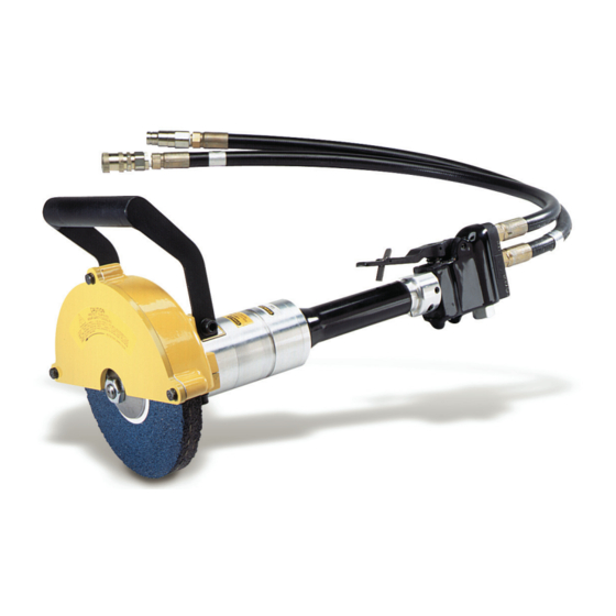
HG80
HG80
HG80
HG80
HG80
M
AINTENANCE
Stanley Hydraulic Tools
3810 SE Naef Road
Milwaukie OR 97267-5698
503-659-5660
FAX 503-652-1780
www.stanley-hydraulic-tools.com
Advertisement
Table of Contents

Related Manuals for Stanley HG80


Summary of Contents for Stanley HG80
- Page 1 Protection AFETY PERATION AND AINTENANCE SERVICE MANUAL Wear Ear Wear Dust Mask Protection Stanley Hydraulic Tools 47351 3810 SE Naef Road Milwaukie OR 97267-5698 503-659-5660 Copyright © 2003, The Stanley Works FAX 503-652-1780 OPS/SVCE USA www.stanley-hydraulic-tools.com 29122 12/2003 Ver 2...
-
Page 3: Table Of Contents
REPAIRS AND / OR SERVICE TO THIS TOOL MUST ONLY BE DONE BY AN AUTHORIZED AND CERTIFIED DEALER. For the nearest authorized and certified dealer, call Stanley Hydraulic Tools at one of the numbers listed on the back of this manual and ask for a Customer Service Representative. -
Page 4: Safety Symbols And Precautions
SAFETY SYMBOLS Safety symbols and signal words, as shown below, are used to emphasize all operator, maintenance and repair actions which, if not strictly followed, could result in a life-threatening situation, bodily injury or damage to equipment. This is the safety alert symbol. It is used to alert you to potential personal injury hazards. -
Page 5: Safety Precautions
Read the Manual Protection The model HG80 Hydraulic Grinder will provide safe and dependable service if oper- ated in accordance with the instructions given in this manual. Read and understand this manual and any stickers and tags attached to the grinder and hose before operation. - Page 6 SAFETY PRECAUTIONS • To avoid personal injury or equipment damage, all tool repair, maintenance and service must only be performed by autho- rized and properly trained personnel. • If the material being ground creates an emission of dust and fumes, use personal protective devices. •...
-
Page 7: Tool Stickers And Tags
USE ONLY PARTS AND REPAIR USE ONLY PARTS AND REPAIR suggest you retain this tag PROCEDURES APPROVED BY PROCEDURES APPROVED BY STANLEY AND DESCRIBED IN THE OPERATION STANLEY AND DESCRIBED IN THE OPERATION and attach it to the tool MANUAL. MANUAL. -
Page 8: Hydraulic Hose Requirements
HOSE SAFETY TAGS To help ensure your safety, the following DANGER tags are attached to all hose purchased from Stanley Hydraulic Tools. DO NOT REMOVE THESE TAGS. If the information on a tag is illegible because of wear or damage, replace the tag immediately. A new tag may be obtained from your Stanley Distributor. -
Page 9: Htma Requirements
HTMA REQUIREMENTS TOOL CATEGORY HYDRAULIC SYSTEM REQUIREMENTS TYPE 1 TYPEII TYPEIII TYPE RR FLOW RATE 4-6 gpm 7-9 gpm 11-13 gpm 9-10.5 gpm (15-23 lpm) (26-34 lpm) (42-49 lpm) (34-40 lpm) TOOL OPERATING PRESSURE 2000 psi 2000 psi 2000 psi 2000 psi (at the power supply outlet) (138 bar) -
Page 10: Operation
OPERATION PREOPERATION NOTE: Use 8 inch by 1 inch thick (Type 1) grinding wheels with a PROCEDURES 5/8 arbor hole. Only use grinding wheels which comply with ANSI B7.1/ISO 525, 603. PREPARATION FOR INITIAL USE 1. Loosen 3 capscrews and lockwashers (64 & 63) and remove the guard front plate (62) and set aside. - Page 11 OPERATION 4. Squeeze the trigger momentarily. If the grinder does not operate, the hoses might be reversed. Verify correct connec- tion of the hoses before continuing. 5. Start the grinder and move the grinding wheel or cone to the work surface. 6.
-
Page 12: Equipment Protection And Care
The circuit RETURN hose (with female quick disconnect) is connected to the opposite port. Do not reverse circuit flow. This can cause damage to internal seals. • Always replace hoses, couplings and other parts with replacement parts recommended by Stanley Hydraulic Tools. Supply hoses must have a minimum working pressure rating of 2500 psi/172 bar. -
Page 13: Troubleshooting
Adjust relief valve to 2100-2250 psi/145-155 bar. Hydraulic motor worn. Inspect, repair or replace. Flow control malfunctioning. Have flow control serviced at an authorized Stanley service center. Grinder operates too fast. Flow control malfunctioning. Have flow control and valve body serviced at an authorized... -
Page 14: Specifications
SPECIFICATIONS Wheel Capacity ......................8 in. dia. x 1 in. thk x 5/8 arbor (type 1) Pressure Range ..........................1000-2000 psi/70-140 bar Maximum Back Pressure ..........................250 psi/17 bar Flow Range ............................. 7-10 gpm/26-38 lpm Optimum Flow .............................. 10 gpm / 38 lpm Porting ................................ -
Page 15: Service
SERVICE 3. Remove 8 capscrews (8) and using a flat-blade screw- driver or similar tool, gently pry the front (13) and rear (16) GRINDER DISASSEMBLY bearing housings apart. Lift the front bearing housing straight up. Do Not tilt the housing or pry on the flat surface inside of the surrounding groove. - Page 16 SERVICE in the fluid and for filter condition. Operating conditions may be flat and free of nicks or burrs that could cause misalign- require changing from a 25-micron filter to an oversized 10- ment or leaks. micron filter. Bushings REASSEMBLY The inside of the bushings should be gray with some bronze showing through.
- Page 17 SERVICE to the trigger (21) and remove the valve spool assembly and tubes making sure the tubes are not twisted and are aligned spring (22). with the correct ports (directly in line with ports in the valve handle and motor). Push the valve handle onto the oil tubes 5.
- Page 18 Loosing grip may result in injury. break-in is accomplished by turning the shaft while applying hydraulic pressure. On the HG80 Grinders this procedure can be accomplished by obtain-ing a 5/8-11 nut and enough thick washers to permit the nut to be tightened against the washers on the spindle shaft.
-
Page 19: Parts Illustration
HG80 PARTS ILLUSTRATION... -
Page 20: Parts List
HG80 PARTS LIST Part Number Part Number Item Item HG80110 HG80120 Description Description HG80110B HG80120B 01298 01298 Lockwasher 25610 25610 Railroad Help Desk Sticker 06316 06316 Bushing 25907 25907 Modified Capscrew 00178 00178 O-ring, 2-1/8 x 2-1/4 x 1/16 -034 70D*... -
Page 21: Warranty
2 years from the shipping date from Stanley, whichever period expires first, to be free of defects in material and/or workmanship at the time of delivery, and will, at its option, repair or replace any tool or part of a tool, or new part, which is found upon examination by a Stanley authorized service outlet or by Stanley’s factory in Milwaukie, Oregon to be DEFECTIVE IN MATERIAL AND/OR WORKMANSHIP. - Page 22 Stanely Hydraulic Tools 3810 SE Naef Road Milwaukie, Oregon 503-659-5660 / Fax 503-652-1780 www.stanley-hydraulic-tools.com...