Advertisement
Available languages
Available languages
Quick Links
D
WALT Industrial Tool Co., 701 East Joppa Road, Baltimore, MD 21286
E
(DEC03-CD-1) Form No. 621650-00
The following are trademarks for one or more D
color scheme; the "D" shaped air intake grill; the array of pyramids on the handgrip; the kit
box configuration; and the array of lozenge-shaped humps on the surface of the tool.
IF YOU HAVE ANY QUESTIONS OR COMMENTS ABOUT THIS OR ANY D
CALL US TOLL FREE AT: 1-800-4-D
Safety Instructions for Levels
WARNING! Read and understand all instructions. Failure to follow all
instructions listed below may result in electric shock, fire and/or serious
personal injury.
SAVE THESE INSTRUCTIONS
DANGER: Do not operate during storms or near high voltage. NEVER attempt to use
a grade rod in a storm or near overhanging electric wires.
DANGER: Do not use optical tools such as a telescope or transit to view a laser
beam. Serious eye injury could result.
DANGER: Always be sure to set up optical instruments so that any user will not
intentionally or accidentally look through the instrument at the sun or any other
source of bright light, keeping in mind that the sun moves throughout the day.
• Store level out of reach of children and other untrained persons.
• Use only accessories that are recommended by the manufacturer for your model.
Accessories that may be suitable for one level, may create a risk of injury when used on
another level.
• Tool service must be performed only by qualified repair personnel. Service or
maintenance performed by unqualified personnel may result in injury. To locate your
nearest D
WALT service center call 1-800-4-D
E
http://www.dewalt.com on the Internet.
• Do not operate the level around children or allow children to operate the level.
Serious eye injury may result.
• Do not remove or deface warning labels.
• Position the level securely on a level surface. Damage to the level or serious injury
could result if the level falls.
WARNING: This product contains chemicals, including lead, known to the State of
California to cause cancer, and birth defects or other reproductive harm. Wash hands after
handling.
• Avoid prolonged contact with dust from power sanding, sawing, grinding, drilling,
and other construction activities. Wear protective clothing and wash exposed
areas with soap and water. Allowing dust to get into your mouth, eyes, or lay on the skin
may promote absorption of harmful chemicals.
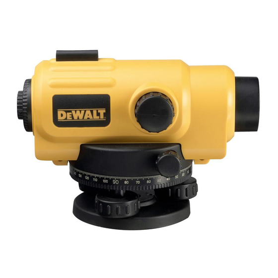
Components (Fig. 1, 2)
A. Base Plate
B. Horizontal Circle
C. Eyepiece (not shown)
D. Optical Peep Sight
E. Objective Cover
To ensure the accuracy of your instrument, check to make sure it is calibrated often. See the
Field Calibration Check section of this manual.
ASSEMBLY
The DW096 Automatic Level is fully assembled at the factory. No further assembly is nec-
essary. See the following instructions regarding the tripod.
Tripod Setup
1. Loosen the straps (K) around the tripod legs. Lift the extension quick-release clamps (L).
2. With the tripod closed, extend the legs so the tripod head is approximately eye level.
Tighten the quick-release clamps.
3. Position the legs in a triangular position. Fix the legs firmly into the ground by pressing
on the tripod shoes (M).
DW096
Copyright © 2003
WALT power tools: the yellow and black
E
WALT (1-800-433-9258)
E
WALT (1-800-433-9258) or go to
E
F. Focusing Knob
G. Horizontal Tangent Drive
H. Leveling Screws
I. Bubble Viewing Prism
J. Circular Bubble
FIG. 1
C
F
G
H
FIG. 3
L
4. Gently remove the level from the carrying case. Note how the level is packed so that it
can be placed back in the same position.
5. Carefully position the instrument in the approximate center of the tripod head as shown
in Figure 3. Insert the tripod centering screw into the base plate, taking care to align the
threads properly. Tighten the screw until the instrument fits snug on the tripod. Do not over-
tighten or strip the threads.
6. Center the circular bubble (J) on the level by turning the leveling screws (H) as shown in
Figure 4.
OPERATION
Pointing and Focusing
1. Point the telescope towards a bright background or hold a white sheet of paper in front
of objective. Turn the eyepiece until the crosshairs are sharp and black.
2. Turn the level towards the staff by using the optical peep sight (D).
3. Looking through the eyepiece, turn the focusing knob (F) until the image of the staff is
sharp and clear.
4. Turn the horizontal tangent drive (G) to set the vertical hair down the center of the staff.
Measuring
HEIGHT MEASUREMENT
Read the staff at the middle stadia line (Fig. 5).
STADIA MEASUREMENT
The Automatic Level is equipped with a stadia reticle so you can make simple distance
estimates. The stadia lines are located in the reticle (Figure 5). Sight the rod, read the two
observations at the stadia lines, take the difference of these observations and multiply by
100 to estimate the distance between the rod and the center of the instrument.
ANGLE MEASUREMENT
1. Sight point A with vertical hair and note the reading "a" on the horizontal circle (Fig. 6).
2. Turn the level to sight point B and note the reading "b".
WALT TOOL,
3. The angle is a – b.
E
Checking and Adjusting
CIRCULAR BUBBLE
1. Center the bubble (J) by using the leveling screws (H), then turn the instrument 180˚.
The bubble should remain centered (Fig. 7). If the bubble moves out of center, the
bubble needs adjustment (Fig. 8).
2. If the bubble needs adjustment, turn the leveling screws to bring the bubble halfway to
the center (Fig. 9). Using the Allen wrench provided, turn the two bubble adjustment
screws to center the bubble (Fig. 10).
3. Repeat the above procedure until the bubble remains centered when the instrument is
turned 180˚.
Field Calibration Check (Fig. 11, 12)
1. Place two rods facing each other at points A and B at a distance of 50 - 80m apart
(Fig. 11). Set up your instrument about halfway between A and B.
2. Sight the rods and take readings on point A as A and on point B as B.
3. Set the instrument at point D which is about 2m from point A (Fig. 12).
4. Sight the rods at point A, take reading as AA. Then, sight the rod at point B, take reading
as BB.
5. Use the following equation to calculate:
The instrument is in its perfect condition if BB' = BB, otherwise, it needs adjustment.
MAINTENANCE
In order to protect all parts and not to lose its accuracy, care must be taken.
1. The instrument should always be kept properly encased when not in use, for maximum
protection.
2. Keep the instrument clean and free of dirt and moisture. After use, clean every part of the
instrument completely before putting it back in its case.
3. The interior parts are not user serviceable. Do not remove any lenses. Do not attempt to
clean, oil or repair interior parts.
4. After working in dusty locations, remove all dust from the lenses with a clean, soft tissue
or cloth and brush the leveling and tangent screws threads with a small brush.
5. When working near moving equipment, never leave your instrument unattended.
6. Make sure not to over tighten the leveling screw, clamp screw or adjusting screw.
7. Always spread the tripod legs to insure a stable setup. When setting up your tripod on an
incline, make sure two of the three legs are on the lower side of the incline. When setting
up on a pavement or other hard surface, try to protect the legs from slipping by either
making holes for the legs to sit in or blocking the legs.
8. It is recommended that a qualified service technician check the instrument periodically.
Accessories
Recommended accessories for use with your tool are available at extra cost from your local
dealer or authorized service center. If you need assistance in locating any accessory for your
tool, contact: D
E
CAUTION: The use of any other accessory not recommended for use with this tool could
be hazardous.
Repairs
To assure product SAFETY and RELIABILITY, repairs, maintenance and adjustment should
be performed by authorized service centers or other qualified service personnel, always
using identical replacement parts.
Full Warranty
D
WALT heavy duty industrial tools are warranted for one year from date of purchase. We
E
will repair, without charge, any defects due to faulty materials or workmanship. For warranty
FIG. 2
D
E
B
A
FIG. 4
K
FRONT
DEVANT
M
FRENTE
BB' = AA – (A – B)
WALT Industrial Tool Co., 701 East Joppa Road, Baltimore, MD 21286.
I
J
H
FRONT
DEVANT
FRENTE
Advertisement

Related Manuals for DeWalt DW096


Summary of Contents for DeWalt DW096
- Page 1 ASSEMBLY CAUTION: The use of any other accessory not recommended for use with this tool could The DW096 Automatic Level is fully assembled at the factory. No further assembly is nec- be hazardous. essary. See the following instructions regarding the tripod.
- Page 2 Vérifier fréquemment l’étalonnage de l’instrument afin d’en assurer la précision. Pour ce faire, consulter la section « Vérification de l’étalonnage sur place » du présent guide. ASSEMBLAGE Le niveau automatique DW096 est complètement assemblé en usine; aucun montage complémentaire n’est requis. Voir les directives suivantes concernant le trépied. Installation du trépied Item/Model 1.
- Page 3 ENSAMBLADO Réparations El nivel automático DW096 viene completamente ensamblado de fábrica. No hay necesidad Pour assurer la SÉCURITÉ et la FIABILITÉ de ce produit, toutes les opérations de répara- de ensamblar nada. Vea las instrucciones siguientes relativos al montaje del trípode.
- Page 4 MANTENIMIENTO PARA REPARACIÓN Y SERVICIO DE SUS HERRAMIENTAS ELÉCTRICAS DIRÍJASE AL CENTRO DE SERVICIO MÁS CERCANO Para que ninguna de las piezas pierdan su precisión, se debe poner cuidado en lo siguiente. AGUASCALIENTES 1. El instrumento debería mantenerse siempre bien guardado en su estuche cuando no se Av.