
Related Manuals for Code Alarm CA 6151


Summary of Contents for Code Alarm CA 6151
- Page 1 PROFESSIONAL SERIES Security and Remote Start Installation Guide for models: CA 6151 CA 6551 CA 6551 SST 2010 Audiovox Electronics Corporation. All rights reserved.
-
Page 2: Table Of Contents
Tach Programming .................. 23 Smart Tachless Mode ................24 Adjusting the Shock Sensor ..............24 Testing the Shock Sensor ..............24 Chirp Delete - User Accessible .............. 24 Dome Light Delay / Theater Dimming ............. 25 2010 Audiovox Electronics Corporation. All rights reserved. -
Page 3: Audiovox Electronics Corporation. All Rights Reserved
Feature Descriptions ................25 Transmitter Button Functions ............. 30 Security Trigger Zones ................. 31 Remote Start Shutdown Diagnostics ..........31 System Layout ..................32 2010 Audiovox Electronics Corporation. All rights reserved. -
Page 4: Before You Begin
Use a Digital Multi Meter for testing and verifying circuits. DO NOT USE A TEST LIGHT, OR "COMPUTER SAFE PROBE" as these can set off air bags or damage vehicle computers. Technical Support (800) 421-3209 or go to http://techservices.codesystems.com 2010 Audiovox Electronics Corporation. All rights reserved. -
Page 5: Wire Connection Guide
BATTERY 12V ( + ) ORANGE ACCESSORY 1 ( + ) PINK/WHITE IGNITION 2 ( + ) RED/WHITE BATTERY 12V ( + ) PINK IGNITION 1 ( + ) 6 Pin Output Harness 2010 Audiovox Electronics Corporation. All rights reserved. -
Page 6: Pin Alternate Output Harness
FACTORY ARM / PULSE AFTER START ( - ) GREEN/WHITE PULSE AFTER SHUTDOWN ( - ) BLACK/YELLOW PULSE DURING CRANK ( - ) 3 Pin Lock Output Harness BLUE UNLOCK ( - ) OPEN GREEN LOCK ( - ) 2010 Audiovox Electronics Corporation. All rights reserved. -
Page 7: Pin Main Harness
Route the BROWN siren output wire from the control module through the firewall and connect to the RED wire on the siren. NOTE: Be sure to loom the siren wires, and seal the grommet. 2010 Audiovox Electronics Corporation. All rights reserved. -
Page 8: Pin Start Harness
Verification: This wire registers voltage when the key is turned to ACC (Accessory) and the ON (or RUN) position. The voltage drops out when the key is turned to the START (or CRANK) position. Connect the ORANGE wire to the vehicle’s accessory wire. 2010 Audiovox Electronics Corporation. All rights reserved. - Page 9 RUN) position. The voltage does not drop out when the key is turned to the START (or CRANK) position. Connect the PINK wire to the vehicle’s Ignition wire. This wire is also used for Ignition 1 Output. 2010 Audiovox Electronics Corporation. All rights reserved.
-
Page 10: Pin Output Harness
Jump To PINK BLUE/BLACK Active Output Accessory Output Wire Ignition Output Wire Wire From Wire From Control Module Control Module To Vehicle's 2nd or 3rd Accessory Wire To Vehicle's 2nd or 3rd Ignition Wire 2010 Audiovox Electronics Corporation. All rights reserved. -
Page 11: Pin Input Harness
8 Pin Input Harness BLUE/WHITE INSTANT TRIGGER INPUT ( - ) This wire is a GROUND input for an external sensor or secondary pin switch. Verification: This wire when connected will trigger the security system. 2010 Audiovox Electronics Corporation. All rights reserved. - Page 12 Verification: This wire when connected will register ground when the vehicle's hood is opened. Connect the GRAY wire to the hood pin. NOTE: Be sure to loom the wire, and seal the grommet. 2010 Audiovox Electronics Corporation. All rights reserved.
- Page 13 Have someone press on the gas pedal slightly as you monitor the meter. If connected to the correct wire, the voltage reading will increase as the engine’s RPM increases. Connect the PURPLE/WHITE wire to the negative side of the vehicle ignition coil or fuel injector. 2010 Audiovox Electronics Corporation. All rights reserved.
-
Page 14: Pin Alternate Output Harness
It can also be used to pulse a door pin-switch wire to prevent the vehicle’s accessories from remaining on after remote start shutdown. 2010 Audiovox Electronics Corporation. All rights reserved. - Page 15 B LAC K /Y E LLOW P uls e S tarter O utput During C rank W ire W ire From T he C ontrol Module To Vehicle's 2nd S tarter W ire 2010 Audiovox Electronics Corporation. All rights reserved.
-
Page 16: Pin Door Lock Output Harness
Verification: These wires will register ground when the Lock and Unlock switches are activated. Connect the GREEN and BLUE wires shown in the diagram below. Negative Locks: GREEN (-) Lock Output Lock Vehicle Door Lock Control Relays Unlock BLUE (-) Unlock Output 2010 Audiovox Electronics Corporation. All rights reserved. - Page 17 (2) SPDT relays (not supplied). Reverse Polarity Locks: Fused +12 Volt Battery Souce GREEN (-) Lock Output Lock To Door Lock Motor Unlock Fused +12 Volt Battery Souce BLUE (-) Unlock Output To Door Lock Motor 2010 Audiovox Electronics Corporation. All rights reserved.
- Page 18 Connect the GREEN and BLUE or BLUE/GREEN wires shown in the diagram below using (2) SPDT relays (not supplied). Multiplex Locks: Fused +12 Volt GREEN (-) Lock Output BLUE (-) Unlock Output Battery Source Resistor Lock Vehicle Door Lock Control Relays Unlock 2010 Audiovox Electronics Corporation. All rights reserved.
- Page 19 BLUE wires shown in the diagram below using (2) SPDT relays (not supplied). Fused +12 Volt Battery Source Door Lock GREEN (-) Lock Output Actuator Chassis Ground Fused +12 Volt Battery Source BLUE (-) Unlock Output Chassis Ground 2010 Audiovox Electronics Corporation. All rights reserved.
-
Page 20: Additional Ports
Factory Alarm Arm / Disarm Diesel Glow Plug Input Manual Arm / Disarm Inputs (factory keyless controls system) Tracking Port This 4 pin port is used for Code Alarm Car Link or Vehicle Tracking accessories. 2010 Audiovox Electronics Corporation. All rights reserved. -
Page 21: Set Up & Programming
Press the transmitter button to change the desired feature. The LED will flash indicating the changed feature. 2010 Audiovox Electronics Corporation. All rights reserved. -
Page 22: Programming Feature Banks
NOTE: The system will remain in feature programming mode as long as the ignition is on, there is no time limit. To exit programming turn the IGNITION OFF. Feature Bank 1 - 3 Chirps Transmitter Programming Refer to transmitter programming. 2010 Audiovox Electronics Corporation. All rights reserved. -
Page 23: Tach Programming
Allow the vehicle to settle to a normal idle speed. Release the valet/program push-button switch. The parking lights will turn on for 2 seconds indicating that the learned tach signal is stored and the unit has exited tach learn mode. 2010 Audiovox Electronics Corporation. All rights reserved. -
Page 24: Smart Tachless Mode
System ARM/DISARM chirps can be toggled ON or OFF without entering the programming feature banks. Turn the ignition ON then OFF. Press and release the valet/programming button 3 times. The system will respond with 1 chirp for ON or 2 chirps for OFF. 2010 Audiovox Electronics Corporation. All rights reserved. -
Page 25: Dome Light Delay / Theater Dimming
3 - Passive Arming: Determines manual or automatic locking of the vehicle’s doors. Active - Requires use of the transmitter to arm the security system. Passive - Automatically arms the security system 1 minute after the last door is closed 2010 Audiovox Electronics Corporation. All rights reserved. - Page 26 Factory Disarm - Single 1 second pulse with unlock and remote start activation. 2nd Unlock - Same ouput as unlock with 2nd press of unlock only. Start Status - Continuous ( - ) output during the remote start cycle. 2010 Audiovox Electronics Corporation. All rights reserved.
- Page 27 3 - Running Lights: Controls the WHITE parking light output wire during remote start. Steady - Parking lights constant during the remote start cycle. Flashing - Parking lights flash at a slow pace during the remote start cycle. 2010 Audiovox Electronics Corporation. All rights reserved.
- Page 28 45 Second Delay - Diesel engine, delays the starter output wire for 45 seconds after the ignition has been powered up by the remote start. 2010 Audiovox Electronics Corporation. All rights reserved.
- Page 29 11 - 2 or 3 Hour Start: When activated, the remote start will activate and run for the programmed time and shut down every 2 or 3 hours. 12 - Turbo Timer: When activated, the vehicle will run for the programmed time. 1 Minute 3 Minutes 5 Minutes 2010 Audiovox Electronics Corporation. All rights reserved.
-
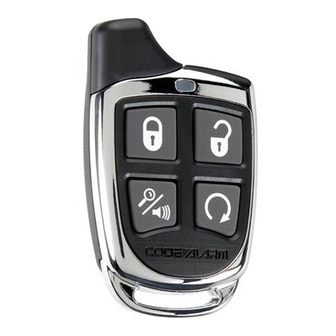
Page 30: Transmitter Button Functions
Turbo Timer Press Unlock + Start Ignition ON/OFF, Press and Hold 2 / 3 Hour Start Valet Button, Press Start 4 times Daily Start Timer Press Lock + Start Menu Press and Hold 2010 Audiovox Electronics Corporation. All rights reserved. -
Page 31: Security Trigger Zones
LED FLASHES SHUTDOWN ZONE 3 Flashes Hood Input Brake Input Neutral Safety Input 4 Flashes Remote Start Valet Mode 7 Flashes Tach not learned / Crank Average not learned 2010 Audiovox Electronics Corporation. All rights reserved. -
Page 32: System Layout
2010 Audiovox Electronics Corporation. All rights reserved. - Page 33 2010 Audiovox Electronics Corporation. All rights reserved.
-
Page 34: Customer Service
2. This device must accept any interference received, including any interference that may cause undesired operation. Warning! Changes or modifications not expressly approved by the party responsible for compliance could void the user’s authority to operate the equipment. 2010 Audiovox Electronics Corporation. All rights reserved.