
Related Manuals for Delta 36-477


Summary of Contents for Delta 36-477
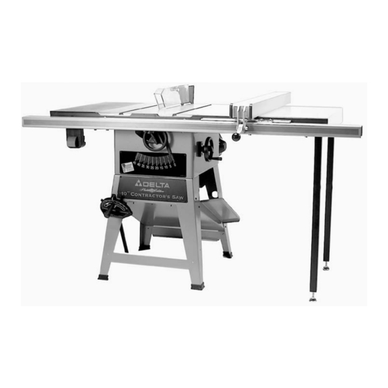
- Page 1 Platinum Edition 10" Contractor’s Saw with 30" Unifence ® (Model 36-477) with 30" Biesemeyer ® (Model 36-485) REVISED 6-15-00 PART NO. 422-19-651-0045 Copyright © 2000 Delta Machinery...
-
Page 2: Safety Rules
SAFETY RULES Woodworking can be dangerous if safe and proper operating procedures are not followed. As with all machinery, there are certain hazards involved with the operation of the product. Using the machine with respect and caution will considerably lessen the possi- bility of personal injury. -
Page 3: Additional Safety Rules For Circular Saws
Delta 10 Contractor’s Saws are designed to give high quality performance with maximum depth of cut capacity up to 3-1/8 at 90° and 2-1/8 at 45° for clean cutting of standard stock sizes. Delta Model 36-477 includes a 30 Unifence T-Slot rail fence system and Model 36-485 includes a 30 Biesemeyer T-Square home shop fence system. -
Page 4: Unpacking And Cleaning
UNPACKING AND CLEANING Carefully unpack the table saw and all loose items from the shipping containers. Remove the protective coating from the machined surfaces of the saw. This coating may be removed with a soft cloth moistened with kerosene (do not use acetone, gasoline or lacquer thinner for this purpose). Fig. 2, illustrates the components of the table saw. - Page 5 1. Combination Dust Chute/ Support Panel 2. Motor Pulley 3. Motor 4. Pulley Guard 5. Drive Belt 6. Spring 7. Pins (2) for Mounting Motor 8. Motor Mounting Plate 9. Lockwashers (4) 10. Flat Washers (4) 11. 5/16-18 x 3/4 Carriage Head Screws (4) 12.
- Page 6 BIESEMEYER T-SQUARE FENCE SYSTEM ® The T-Square Commercial Fence System includes the fence assembly, front rail, rear rail, front guide tube and right extension table Model 78-927 for 30 capacity. ® IMPORTANT: The T-Square Fence System is designed to be used ONLY with a supporting extension table.
- Page 7 Fig. 5 Fig. 6...
- Page 8 Fig. 7...
-
Page 9: Assembling Saw Stand
ASSEMBLY INSTRUCTIONS ASSEMBLING SAW STAND 1. Assemble the dust chute and support panel (A) Fig. 8, to the inside of the front stand panel (B) with three Fig. 8 #10 x 1/2 sheet metal screws (C), four #10-32 x 1/2 screws (D), and four hex nuts (E). -
Page 10: Assembling Saw To Stand
ASSEMBLING SAW TO STAND 1. Fig. 11, illustrates the stand (B) completely assem- bled. 2. Assemble rubber foot (A) Fig. 11, onto the end of each stand leg (B). Insert grommet (C) into hole (D) in stand leg. 3. Carefully place saw (E) Fig. 12, onto saw stand (B). Align eight holes in the top of stand (B) with mounting holes in the bottom of saw (E) and fasten with eight screws, flat washers, lockwashers, and hex nuts (F) Fig. -
Page 11: Assembling Motor And Motor Mounting Plate To Saw
MOTOR The motor shipped with your saw is a 1-1/2 H.P., Ball Bearing, Capacitor Start/Capacitor Run, 115/230 Volt motor. This motor has been specially selected to best supply power to your machine and the relative safety of the machine is enhanced by its use. We, therefore, strongly suggest that only this motor be used, as the use of other motors may be detrimental to the performance and safety of the saw. -
Page 12: Assembling Motor Pulley, Belt And Pulley Guard, And Drive Belt
ASSEMBLING MOTOR PULLEY, BELT AND PULLEY GUARD, AND DRIVE BELT WARNING: WHEN ASSEMBLING MOTOR PULLEY, BELT AND PULLEY GUARD, AND DRIVE BELT, MAKE CERTAIN THE MOTOR IS DISCONNECTED FROM THE POWER SOURCE. 1. Remove the motor shaft key that is taped to the motor. - Page 13 7. Lift the motor and assemble the drive belt (H) Fig. 23, to the arbor pulley and motor pulley (B). The weight of the motor will provide the correct belt tension. Fig. 23 8. WARNING: IMMEDIATELY AFTER ASSEMBLING THE BELT, RAISE THE SAW BLADE TO ITS MAXIMUM HEIGHT AND TILT THE SAW BLADE TO 45 DEGREES.
-
Page 14: Assembling Blade Guard And Splitter Assembly
2. Fig. 27, illustrates the motor cord connected to the switch assembly. Fig. 27 ASSEMBLING BLADE GUARD AND SPLITTER ASSEMBLY WARNING: MAKE CERTAIN THE SAW IS DISCON- NECTED FROM THE POWER SOURCE. 1. Fasten the rear splitter mounting bracket (A) Fig. 28, to the rear trunnion using the two 3/4 hex head screws (B) and flat washers. - Page 15 5. If an alignment is necessary, loosen the two screws (F) Fig. 31, align bracket (D) with the arbor flange (E) and tighten screws (F). 6. Loosely assemble large washer and screw (C) Fig. 31, to the inside splitter bracket. This screw and washer was removed in STEP 3.
- Page 16 9. With the blade guard (L) Fig. 35, in the raised posi- tion, assemble the saw blade (K) on the saw arbor with two arbor wrenches supplied. Fig. 35 10. Using a straight edge, check to see if the saw blade is aligned with the rear of the splitter (G), as shown in Figs.
-
Page 17: Assembling Extension Wing
ASSEMBLING EXTENSION WING 1. Assemble extension wing (A) Fig. 39, to the saw table using three 7/16-20 x 1-1/4 screws (B) and lock- washers (C) as shown in Fig. 39. Fig. 39 2. With a straight edge (D) Fig. 39, make certain the extension wing (A) is level with the saw table before tightening three screws (B) Fig. -
Page 18: Assembling Table Mounting Brackets To Saw Table
ASSEMBLING TABLE MOUNTING BRACKETS TO SAW TABLE 1. Assemble Z-brackets (A) Fig. 43, to the three tapped holes at the inside edge on the right side of saw table (B), using three 7/16-20 x 3/4 hex head screws (C) with flat washers and lockwashers. - Page 19 UNIFENCE ASSEMBLY INSTRUCTIONS ASSEMBLING TABLE LEGS AND FRONT TABLE SUPPORT Fig. 48 1. The table board supplied will require thirteen loca- tions to be marked on the bottom of the table board at the locations illustrated in Fig. 48. NOTE: The table board should be positioned so that the edge with no veneer is on the side that will be attached to the exten- sion wing.
- Page 20 4. Insert foot adapter (T) Fig. 51, into the bottom of each leg (A). Assemble the 3/8 jam nut (V) Fig. 51, approximately 3/4 of the way onto leveling screw (W) and place a flat washer (X) on the level- ing screw.
-
Page 21: Assembling Unifence Table To Saw
ASSEMBLING UNIFENCE TABLE TO SAW 1. Position table board (A) Fig. 54, onto angle brackets (B). Fig. 54 2. While holding table board firmly against the saw table, fasten table to three angle brackets (B) Fig. 55, using three #8 x 7/8 long wood screws (C). CAUTION: NOT OVER-TIGHTEN TABLE MOUNTING SCREWS. -
Page 22: Assembling Unifence Guide Rail
ASSEMBLING UNIFENCE GUIDE RAIL 1. Locate the T-Slot Guide Rail and mounting hardware Fig. 59, from the packing material of the Unifence. Remove the end caps (A) Fig. 59, prior to assembly, by inserting a flat headed screwdriver (B) into the channel and tap gently as shown. - Page 23 7. Move the square (H) Fig. 62, to the end of the Unifence table and check to make certain the same dis- tance is kept from the top surface of the extension table (K) to the top surface of the guide rail (C). Move the front table support (L) Fig.
-
Page 24: Assembling Cursor To Unifence Body
Fig. 70 Fig. 68 Fig. 69 Fig. 71 ASSEMBLING CURSOR TO UNIFENCE BODY 1. Remove two screws and flat washers (A) Fig. 68, and assemble the cursor (B) to the Unifence body (C). Replace the two screws and flat washers (A). 2. - Page 25 Fig. 74 Fig. 75 ASSEMBLING UNIFENCE TO UNIFENCE BODY 1. The fence (A) can be assembled to clamp plate (B) in either the horizontal position as shown in Fig. 74, or the vertical position as shown in Fig. 75. Make certain the two lock knobs (C), are loose and slide fence (A) onto clamp plate (B) as shown.
- Page 26 Fig. 79 Fig. 80 3. Using the template (D) Figures 78 and 79, check and adjust front rail at both ends of the saw table as shown, to make sure rail (A) is level with table surface and tighten rail mounting hardware (B). IMPORTANT: Template (D) must be on saw table when checking, not on extension wing.
- Page 27 ² 5- 3/8 ² 2- 3/8 ² 1- 3/4 Fig. 83 Fig. 82 7. Mark the position of the four leg mounting holes from each end of the table as shown in Fig. 82. Using a 1/4 drill bit, drill four through holes through the end piece (J) of the table at the dimensions shown at (K) (L) and (M).
- Page 28 Fig. 87 11. After the holes have been drilled in the edge of the front and rear extension table board, fasten both front and rear rail to table using the 1-1/2 flat head Phillips screws (T) Fig. 87, 1-1/4 O.D. flat washers (U) and hex nuts (V). NOTE: The 1-1/4 flat washer cannot be used on the end holes (X).
-
Page 29: Connecting Saw To Power Source
CONNECTING SAW TO POWER SOURCE POWER CONNECTIONS A separate electrical circuit should be used for your tools. This circuit should not be less than #12 wire and should be protected with a 20 Amp fuse. Have a certified electrician replace or repair a worn cord immediately. -
Page 30: 230 Volt, Single Phase Operation
115 VOLT, SINGLE PHASE OPERATION 1. This tool must be grounded while in use to protect the operator from electric shock. The motor recommended GROUNDED OUTLET BOX for use with your saw is shipped wired for 115 volts and CURRENT is intended for use on a circuit that has an outlet which CARRYING looks like the one illustrated in Fig. -
Page 31: Fastening Stand To Supporting Surface
FASTENING STAND TO SUPPORTING SURFACE IF DURING OPERATION THERE IS ANY TENDENCY FOR THE SAW TO TIP OVER, SLIDE OR WALK ON THE SUPPORTING SURFACE, THE SAW STAND CAN BE SECURED TO THE FLOOR SURFACE. THE RUBBER FEET OF THE STAND FEATURE HOLES WHICH ALLOW EASY MOUNTING WITHOUT REMOV- ING THE SAW FROM THE STAND. -
Page 32: Raising And Lowering The Blade
RAISING AND LOWERING THE BLADE To raise the saw blade, loosen lock knob (A) Fig. 98, and turn the blade raising handwheel (B) clockwise. When the blade is at the desired height, tighten lock knob (A). To lower the blade, loosen lock knob (A) Fig. 98, and turn the handwheel (B) counterclockwise. -
Page 33: Backlash Adjustments For Blade Raising And Blade Tilting Mechanisms
BACKLASH ADJUSTMENTS FOR BLADE RAISING AND BLADE TILTING MECHANISMS After a period of extended use, if any play is detected in the blade raising or blade tilting mechanisms, the follow- ing adjustments should be made. 1. Make certain the machine is disconnected from the power source. -
Page 34: Miter Gage Operation And Adjustment
ADJUSTING BLADE ALIGNMENT WARNING: Blade Alignment is Factory Set and should not need adjustment. Adjusting Blade Alignment, in the field, is a difficult and time-consuming procedure. All Saw Blades have some run-out, therefore re-adjusting blade alignment should only be attempted if it becomes necessary. -
Page 35: Adjusting Table Insert
ADJUSTING TABLE INSERT MAKE CERTAIN THE MACHINE IS DISCONNECTED FROM THE POWER SOURCE. Place a straight edge across the table at both ends of the table insert as shown in Fig. 105. The table insert (A) should always be level with the table. If an adjustment is necessary, turn the adjusting screws (B), as needed. -
Page 36: Storing The Miter Gage, Rip Fence, And Arbor Wrenches
STORING THE MITER GAGE, RIP FENCE, AND ARBOR WRENCHES 1. When not in use, the miter gage (A) Fig. 108, can be stored through the hole located at the front side of the stand as shown. 2. The rip fence (B) Fig. 108, can be conveniently stored out-of-the-way on the stamped ledges on the right side of the saw stand. - Page 37 4. To move the fence along the guide rail, simply lift up clamp lever (A), as shown in Fig. 112, slide fence to desired position on the rail, and push down on clamp lever (A) to lock fence in place. Fig.
-
Page 38: Repositioning Motor For Storage
ADJUSTING FENCE 90 DEGREES TO TABLE The fence must be adjusted so that the face of fence (A) Fig. 116, is 90 degrees to the table. To check if the fence is 90 degrees to the table, place a square (B) on the table with one end of the square against the fence, as shown. - Page 39 OPERATIONS Common sawing operations include ripping and cross-cutting plus a few other standard operations of a fundamental nature. As with all power tools, there is a certain amount of hazard involved with the operation and use of the tool. Using the tool with the respect and caution demanded as far as safety precautions are concerned, will considerably lessen the possibility of personal injury.
-
Page 40: Using The Fence As A Cut-Off Gage
USING THE FENCE AS A CUT-OFF GAGE The fence can be used as a cut-off gage when cross cutting a number of pieces to the same length. IMPOR- TANT: WHEN USING THE FENCE AS A CUT-OFF GAGE, IT IS VERY IMPORTANT THAT THE REAR END OF THE FENCE BE POSITIONED IN FRONT OF THE SAW BLADE. -
Page 41: Ripping On Left Side Of Saw Blade
Fig. 126 Fig. 127 If the ripped work is less than 4 inches wide, a push stick should always be used to complete the feed, as shown in Fig. 126. The push stick can easily be made from scrap material as explained in the section “CON- STRUCTING PUSH STICK.”... -
Page 42: Using Accessory Moulding Cutterhead
USING ACCESSORY MOULDING CUTTERHEAD Moulding is cutting a shape on the edge or face of the work. Cutting mouldings with a moulding cutterhead in the circular saw is a fast, safe and clean operation.The many different knife shapes available make it possible for the operator to produce almost any kind of mouldings, such as various styles of corner moulds, picture frames, table edges, etc. -
Page 43: Using Accessory Dado Head
It is necessary when using the moulding cutterhead to add wood-facing (C) to the face of the rip fence, as shown in Fig. 135. The wood-facing is attached to the fence with wood screws through holes which must be drilled in the fence. 3/4 inch stock is suitable for most work although an occasional job may require 1 inch fac- ing. - Page 44 The dado head set (D) Fig. 139, is assembled to the saw arbor as shown. IMPORTANT: The blade guard and splitter assembly cannot be used when dadoing and must be removed or swung to the rear of the saw as explained previously in this manual.
-
Page 45: Adjusting Fence Parallel To Miter Gage Slots
BIESEMEYER T-SQUARE FENCE SYSTEM FENCE OPERATION IMPORTANT: Before operating fence, make sure the fence is adjusted parallel to the miter gage slot, as explained later on in this manual. Fig. 142 Fig. 143 1. To move the fence along the guide rail, simply lift up clamp lever (A) as shown in Fig. -
Page 46: Adjusting Clamping Action Of Fence Locking Handle
Fig. 146 ADJUSTING CLAMPING ACTION OF FENCE LOCKING HANDLE When the fence locking handle (A) is pushed to the down position, as shown in Fig. 147, the fence assembly (B) should be completely clamped to the guide tube (C). If the fence assembly (B) is not completely clamped to the guide tube (C) when the handle (A) is pushed down, as shown in Fig. -
Page 47: Constructing A Push Stick
CONSTRUCTING A PUSH STICK When ripping work less than 4 inches wide, a push stick should be used to complete the feed and could easily be made from scrap material by following the pattern shown in Fig.150. - Page 48 ACCESSORIES The testing of this unit has been accom- plished with the following accessories. For safest operation, it is recommended that only these accessories be used with this unit. WARNING: Since accessories other than those listed have not been tested with this unit, use of such accessories could be hazardous.
-
Page 51: Parts, Service Or Warranty Assistance
PARTS, SERVICE OR WARRANTY ASSISTANCE All Delta Machines and accessories are manufactured to high quality standards and are serviced by a network of Porter-Cable/Delta Factory Service Centers and Delta Authorized Service Stations. To obtain additional information regarding your Delta quality product or to obtain parts, service, warranty assistance, or the location of the nearest service outlet, please call 1-888-848- 5175. - Page 52 Delta Building Trades and Home Shop Machinery Two Year Limited Warranty Delta will repair or replace, at its expense and at its option, any Delta machine, machine part, or machine accessory which in normal use has proven to be defective in workmanship or material, provided that the customer returns the product prepaid to a Delta factory service center or autho- rized service station with proof of purchase of the product within two years and provides Delta with reasonable opportunity to verify the alleged defect by inspection.
- Page 53 • PORTER-CABLE DELTA SERVICE CENTERS • (CENTROS DE SERVICIO DE PORTER-CABLE DELTA) Parts and Repair Service for Porter-Cable•Delta Power Tools are Available at These Locations • (Obtenga Refaccion de Partes o Servicio para su Herramienta en los Siguientes Centros de Porter-Cable Delta) MISSOURI OREGON...