Table of Contents
Advertisement
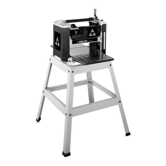
12½" Portable Planer
(Model TP400LS)
PART NO. A02473 - 04-06-04
Copyright © 2004 Delta Machinery
To learn more about DELTA MACHINERY
ESPAÑOL: PÁGINA 21
visit our website at: www.deltamachinery.com.
For Parts, Service, Warranty or other Assistance,
1-800-223-7278 (
1-800-463-3582).
please call
In Canada call
Advertisement
Table of Contents

Related Manuals for Delta ShopMaster TP400LS


Summary of Contents for Delta ShopMaster TP400LS
- Page 1 12½" Portable Planer (Model TP400LS) PART NO. A02473 - 04-06-04 Copyright © 2004 Delta Machinery To learn more about DELTA MACHINERY ESPAÑOL: PÁGINA 21 visit our website at: www.deltamachinery.com. For Parts, Service, Warranty or other Assistance, 1-800-223-7278 ( 1-800-463-3582). please call...
-
Page 2: Safety Guidelines - Definitions
If you have any questions relative to a particular application, DO NOT use the machine until you have first contacted Delta to determine if it can or should be performed on the product. - Page 3 13. USE RECOMMENDED ACCESSORIES. The use of accidents and injury. accessories and attachments not recommended by Delta may cause damage to the machine or injury to the 2. WEAR EYE PROTECTION. ALWAYS USE SAFETY user. GLASSES. Also use face or dust mask if cutting operation is dusty.
- Page 4 ADDITIONAL SAFETY RULES FOR PLANERS FAILURE TO FOLLOW THESE RULES MAY RESULT IN SERIOUS INJURY. DO NOT OPERATE THIS MACHINE until it is 14. ALLOW THE CUTTERHEAD TO REACH FULL SPEED before feeding a workpiece. Changing speeds completely assembled and installed according to the instructions.
-
Page 5: Power Connections
POWER CONNECTIONS A separate electrical circuit should be used for your machines. This circuit should not be less than #12 wire and should be protected with a 20 Amp time lag fuse. If an extension cord is used, use only 3-wire extension cords which have 3- prong grounding type plugs and matching receptacle which will accept the machine’s plug. -
Page 6: Extension Cords
EXTENSION CORDS Use proper extension cords. Make sure your extension cord is in good condition and is a 3-wire extension cord which has a 3-prong grounding type plug and matching receptacle which will accept the machine’s plug. When using an extension cord, be sure to use one heavy enough to carry the current of the machine. An undersized cord will cause a drop in line voltage, resulting in loss of power and overheating. -
Page 7: Functional Description
FUNCTIONAL DESCRIPTION FOREWORD Delta ShopMaster Model TP400LS is a 12½" (317mm) Portable Planer. This planer can handle workpieces up to 12½" (317mm) wide and 6" (152mm) thick. The maximum depth of cut is 3/32" (3mm). The features include basic machine with powerful 15 amp, 120 volt motor, two-knife cutterhead with double-edged reversible knives, knife-installation tool, stand, and wrench. - Page 8 PLANER PARTS 1 - 12½" Portable Planer 2 - Cutterhead raising and lowering handle 3 - M5x.8x20mm hex socket head screw 4 - Cutterhead lock handle 5 - M6x20mm specia hex socket head screw 6 - Wrench and handle assembly Fig.
- Page 9 LOWERING EXTENSION TABLES The infeed and outfeed table extensions (A) Fig. 4, are shipped attached to the machine in the “UP” position. Rotate both table extensions to the down position as shown. The top surface of the table extensions should be level with the planer table.
- Page 10 2. Fasten cutterhead raising and lowering handle (A) Fig. 8, to shaft using the M5x.8x20mm hex socket head screw (C) with wrench supplied. Fig. 8 3. Rotate handle (A) to the operating position as shown in Fig. 9, and tighten set screw (D). Fig.
-
Page 11: Operating Controls And Adjustments
OPERATING CONTROLS AND ADJUSTMENTS STARTING AND STOPPING PLANER The on/off switch (A) Fig. 14, is located on the front of the planer motor. To turn the machine “ON” move the switch up to the “ON” position. To turn the machine “OFF”... - Page 12 RECOMMENDED DEPTH OF CUT 3/32" NOTE: One revolution of the raising and lowering handle will move the cutterhead up or down 3/32 of an inch. SOFT WOOD A 3/32" depth of cut can be made in soft woods on 1/16" HARD WOOD stock up to 8"...
- Page 13 KNIFE TRANSFER TOOL STORAGE 1. The knife transfer tool (A) Fig. 20, supplied with your planer, can easily be stored underneath the outfeed table extension (B) when not being used. A Velcro strip (C) is provided on the tool and underneath the table for this purpose.
-
Page 14: Replacing Knives
Fig. 22 Fig. 23 CARRYING HANDLE/STOCK TRANSFER BAR 1. Your planer is provided with a foam covered carrying handle (A) Fig. 22, located on top of the machine, for ease in transporting the planer. Carrying handles are also provided at the base of the planer on each side which allow you to lift the machine with ease. - Page 15 5. Figure 26 illustrates the cutterhead (C) locked in place allowing access to the knife locking bar (E). Fig. 26 6. Using the supplied wrench (E) Fig. 27, unscrew the six screws, five of which are shown at (F), only enough until locking bar (D) separates from knife, allowing knife to be removed.
- Page 16 9. Remove knife transfer tool and tighten the six screws, five of which are shown at (F) Fig. 30, using wrench (E) supplied. 10. Replace other knife by rotating head 180 degrees and repeat STEPS 5 THROUGH 10. Fig. 30 11.
-
Page 17: Operation
2. Make sure the knives are inserted into the cutterhead properly, as explained under “REPLACING KNIVES.” 3. Place the gage block (A) Fig. 34, on the table, over a 0.020" feeler gage and position the gage block (A) directly underneath the cutterhead. Raise or lower the head assembly and rotate the cutterhead, by following STEP 5 under “REPLACING KNIVES,”... -
Page 18: Maintenance
MAINTENANCE BRUSH INSPECTION AND REPLACEMENT DISCONNECT MACHINE FROM POWER SOURCE. Brush life varies. It depends on the load on the motor. Check the brushes after the first 50 hours of use for a new machine or after a new set of brushes has been installed. - Page 19 NOTES...
-
Page 20: Parts, Service Or Warranty Assistance
Two Year Limited New Product Warranty Delta will repair or replace, at its expense and at its option, any new Delta machine, machine part, or machine accessory which in normal use has proven to be defective in workmanship or material, provided that the customer returns the product prepaid to a Delta factory service center or authorized service station with proof of purchase of the product within two years and provides Delta with reasonable opportunity to verify the alleged defect by inspection. - Page 21 Fax: (519) 767-4131 Fax: (604) 420-3522 Fax: (514) 336-3505 The following are trademarks of PORTER-CABLE • DELTA (Las siguientes son marcas registradas de PORTER-CABLE • DELTA S.A.) (Les marques suivantes sont des marques de fabriquant de la PORTER-CABLE • DELTA): Auto-Set ®...